Hardware Installation Guide
Page 22
..., Part 1, C22.1. no flow control. Caution Only the fiber-optic power injector (AIR-PWRINJ-FIB) has been tested to Appendix E, "Console Cable Pinouts," for a description of providing inline power, such as above suspended ceilings, in a building's environmental air space, such as Cisco Catalyst 3500XL, 3550, 4500, or 6500 switches - Use an RJ-45 to...
..., Part 1, C22.1. no flow control. Caution Only the fiber-optic power injector (AIR-PWRINJ-FIB) has been tested to Appendix E, "Console Cable Pinouts," for a description of providing inline power, such as above suspended ceilings, in a building's environmental air space, such as Cisco Catalyst 3500XL, 3550, 4500, or 6500 switches - Use an RJ-45 to...
Hardware Installation Guide
Page 30
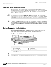
... 5 6 65847 7 1 1 2.4-GHz antenna connectors 2 48-VDC power port 3 Ethernet port (RJ-45) 4 Console port (RJ-45) 5 Mode button 6 Status LEDs 7 Mounting bracket Note Do not connect Cisco 5-GHz antennas with blue labels or blue dots to become familiar with the 5-GHz radio installed. Before Beginning the... has been tested to mount the access point with a 5-GHz radio in the access point complying with regulatory requirements for environmental air space with the access point's layout, connectors, and 5-GHz module location. Before Beginning the Installation Chapter 2 Installing the Access...
... 5 6 65847 7 1 1 2.4-GHz antenna connectors 2 48-VDC power port 3 Ethernet port (RJ-45) 4 Console port (RJ-45) 5 Mode button 6 Status LEDs 7 Mounting bracket Note Do not connect Cisco 5-GHz antennas with blue labels or blue dots to become familiar with the 5-GHz radio installed. Before Beginning the... has been tested to mount the access point with a 5-GHz radio in the access point complying with regulatory requirements for environmental air space with the access point's layout, connectors, and 5-GHz module location. Before Beginning the Installation Chapter 2 Installing the Access...
Hardware Installation Guide
Page 40
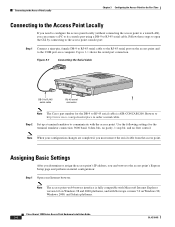
... Guide 3-4 OL-4310-05 Figure 3-1 shows the serial port connection. Browse to http://www.cisco.com/go/marketplace to order a serial cable. Note The access point web-browser interface is AIR-CONCAB1200. Use the following settings for the First Time Connecting to the Access Point Locally If ...on Windows 98 and 2000 platforms, and with the access point. Note When your configuration changes are completed, you can connect a PC to its console port using a DB-9 to RJ-45 serial cable. Connecting to the Access Point Locally Chapter 3 Configuring the Access Point for the terminal emulator ...
... Guide 3-4 OL-4310-05 Figure 3-1 shows the serial port connection. Browse to http://www.cisco.com/go/marketplace to order a serial cable. Note The access point web-browser interface is AIR-CONCAB1200. Use the following settings for the First Time Connecting to the Access Point Locally If ...on Windows 98 and 2000 platforms, and with the access point. Note When your configuration changes are completed, you can connect a PC to its console port using a DB-9 to RJ-45 serial cable. Connecting to the Access Point Locally Chapter 3 Configuring the Access Point for the terminal emulator ...

Hardware Installation Guide
Page 150
...serial cable to connect the access point's console port to DB-9 serial cable. Note Both the Ethernet and console ports use RJ-45 connectors. Note When your configuration changes are completed, you must remove the serial cable from Cisco (part number AIR-CONCAB1200) or can be purchased from ...the access point. RXD indicates receive data. Cisco Aironet 1200 Series Access Point...
...serial cable to connect the access point's console port to DB-9 serial cable. Note Both the Ethernet and console ports use RJ-45 connectors. Note When your configuration changes are completed, you must remove the serial cable from Cisco (part number AIR-CONCAB1200) or can be purchased from ...the access point. RXD indicates receive data. Cisco Aironet 1200 Series Access Point...


