
Hardware Installation Guide
Page 3
... 1-7 Feature Summary 1-7 Hardware Features 1-9 Serial Number Location 1-9 LED Indicators on the Routers 1-9 Integrated 802.11b/g Radio Module (Wireless Models Only) 1-11 Supported Cisco Radio Antennas (Wireless Models Only) 1-12 External Power-over-Ethernet Module (Optional) 1-12 LED Indicators on the PoE Module 1-16 Router Memory 1-16 Router Hardware Security 1-17 Regulatory Compliance 1-17 Preinstallation Information 2-1 Safety Warnings and...
... 1-7 Feature Summary 1-7 Hardware Features 1-9 Serial Number Location 1-9 LED Indicators on the Routers 1-9 Integrated 802.11b/g Radio Module (Wireless Models Only) 1-11 Supported Cisco Radio Antennas (Wireless Models Only) 1-12 External Power-over-Ethernet Module (Optional) 1-12 LED Indicators on the PoE Module 1-16 Router Memory 1-16 Router Hardware Security 1-17 Regulatory Compliance 1-17 Preinstallation Information 2-1 Safety Warnings and...
Hardware Installation Guide
Page 4
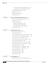
...Router and PoE Module Mounting Procedures 3-1 Connecting Antennas to the Wireless Router 3-1 Mounting on a Table 3-1 Mounting on a Wall 3-2 Guidelines for Wall Mounting 3-2 Mounting the Router on a Wall 3-2 Mounting the PoE Module on a Wall 3-5 What to Do Next 3-6 Router Cabling Procedures 4-1 Cabling for Nonwireless Routers 4-2 Typical Installations 4-2 Connecting the Radio Antennas to the Wireless Router... Router Operations 4-24 What to Do Next 4-25 Initial Configuration 5-1 Installing Cisco Router and Security Device Manager 5-1 Cisco 850 Series and Cisco 870 Series Access Routers Hardware...
...Router and PoE Module Mounting Procedures 3-1 Connecting Antennas to the Wireless Router 3-1 Mounting on a Table 3-1 Mounting on a Wall 3-2 Guidelines for Wall Mounting 3-2 Mounting the Router on a Wall 3-2 Mounting the PoE Module on a Wall 3-5 What to Do Next 3-6 Router Cabling Procedures 4-1 Cabling for Nonwireless Routers 4-2 Typical Installations 4-2 Connecting the Radio Antennas to the Wireless Router... Router Operations 4-24 What to Do Next 4-25 Initial Configuration 5-1 Installing Cisco Router and Security Device Manager 5-1 Cisco 850 Series and Cisco 870 Series Access Routers Hardware...
Hardware Installation Guide
Page 8
... guide. Chapter 3, "Router and PoE Module Mounting Describes how to mount the router before Procedures" connecting devices to additional information and material. Chapter 5, "Initial Configuration" Provides the procedures for cables that you might do something that might need to supply. Caution This symbol means reader be careful. Cisco 850 Series and Cisco 870 Series Access...
... guide. Chapter 3, "Router and PoE Module Mounting Describes how to mount the router before Procedures" connecting devices to additional information and material. Chapter 5, "Initial Configuration" Provides the procedures for cables that you might do something that might need to supply. Caution This symbol means reader be careful. Cisco 850 Series and Cisco 870 Series Access...

Hardware Installation Guide
Page 22
... sends a signal to a wireless LAN using the command-line interface (CLI). Provides 2-wire or 4-wire connection to the factory default. Integrated 802.11b/g radio module (Optional) Provides connectivity to warn the digital subscriber line access multiplexer (DSLAM) about software security features, see the Cisco 850 Series and Cisco 870 Series Access Routers Software Configuration Guide...
... sends a signal to a wireless LAN using the command-line interface (CLI). Provides 2-wire or 4-wire connection to the factory default. Integrated 802.11b/g radio module (Optional) Provides connectivity to warn the digital subscriber line access multiplexer (DSLAM) about software security features, see the Cisco 850 Series and Cisco 870 Series Access Routers Software Configuration Guide...

Hardware Installation Guide
Page 26
...PoE module has an independent power source that can provide inline power to devices connected to each of the four Ethernet ports, so that connects to the Ethernet ports on the router on one side (To ROUTER) and to a drop-ceiling cross member. Table 1-3 Cisco Antennas Supported on the Cisco 850 series and Cisco 870 series wireless routers... Features Chapter 1 Product Overview Supported Cisco Radio Antennas (Wireless Models Only) Table 1-3 lists the Cisco antennas that are supported on the Cisco 850 Series and Cisco 870 Series Wireless Routers Cisco Part Number 23.7786.51 Antenna Type...
...PoE module has an independent power source that can provide inline power to devices connected to each of the four Ethernet ports, so that connects to the Ethernet ports on the router on one side (To ROUTER) and to a drop-ceiling cross member. Table 1-3 Cisco Antennas Supported on the Cisco 850 series and Cisco 870 series wireless routers... Features Chapter 1 Product Overview Supported Cisco Radio Antennas (Wireless Models Only) Table 1-3 lists the Cisco antennas that are supported on the Cisco 850 Series and Cisco 870 Series Wireless Routers Cisco Part Number 23.7786.51 Antenna Type...

Hardware Installation Guide
Page 27
... Features Caution To ensure proper PoE module operation, do not connect the PoE module power supply to the PoE module before you connect the PoE module to the Ethernet ports on the back panel. Do not connect ISDN devices to the router. The integrated cable below the cable number ...on the PoE module; doing so may damage the hardware. Figure 1-12 1 Power-over -Ethernet Module Back Panel 1 2 PWR 0 1 2 3 TO LAN 121039 1 LED indicators and Ethernet ports for connecting powered devices 2 Power indicator OL-5331-01 Cisco 850 Series and Cisco 870 Series Access Routers Hardware ...
... Features Caution To ensure proper PoE module operation, do not connect the PoE module power supply to the PoE module before you connect the PoE module to the Ethernet ports on the back panel. Do not connect ISDN devices to the router. The integrated cable below the cable number ...on the PoE module; doing so may damage the hardware. Figure 1-12 1 Power-over -Ethernet Module Back Panel 1 2 PWR 0 1 2 3 TO LAN 121039 1 LED indicators and Ethernet ports for connecting powered devices 2 Power indicator OL-5331-01 Cisco 850 Series and Cisco 870 Series Access Routers Hardware ...

Hardware Installation Guide
Page 28
Hardware Features Figure 1-14 Installing the PoE Module Chapter 1 Product Overview 1 1 LEFT 0 SN: XXXNNNNXXXX LAN FE0 FE1 FE2 FE3 Cisco 871W WAN FE4 RESET CONSOLE AUX +5,+12 VDC RIGHT / PRIMARY 2 PWR 7 0 1 2 3 To LAN 5 3 6 4 1 Cisco 870 series router 2 Ethernet cables on the PoE module (four RJ-45 connectors in series) 3 PoE module 4 PoE power adapter 5 Router power adapter 6 PoE power plug 7 Router power plug 122351 1-14 Cisco 850 Series and Cisco 870 Series Access Routers Hardware Installation Guide OL-5331-01
Hardware Features Figure 1-14 Installing the PoE Module Chapter 1 Product Overview 1 1 LEFT 0 SN: XXXNNNNXXXX LAN FE0 FE1 FE2 FE3 Cisco 871W WAN FE4 RESET CONSOLE AUX +5,+12 VDC RIGHT / PRIMARY 2 PWR 7 0 1 2 3 To LAN 5 3 6 4 1 Cisco 870 series router 2 Ethernet cables on the PoE module (four RJ-45 connectors in series) 3 PoE module 4 PoE power adapter 5 Router power adapter 6 PoE power plug 7 Router power plug 122351 1-14 Cisco 850 Series and Cisco 870 Series Access Routers Hardware Installation Guide OL-5331-01

Hardware Installation Guide
Page 29
Chapter 1 Product Overview Figure 1-15 Connecting the PoE Module to the Router Hardware Features 1 LEFT 0 3 21 Cisco 871W SN: XXXNNNNXXXX LAN WAN FE0 FE1 FE2 FE3 FE4 RESET CONSOLE AUX +5,+12 VDC RIGHT / PRIMARY 142607 PWR 4 0 1 2 3 To LAN 1 Cisco 870 series router 2 RJ-45 Ethernet ports on the router 3 Four RJ-45 Ethernet plugs, in series, from the PoE module (plug these into the Ethernet ports on the router) 4 PoE module OL-5331-01 Cisco 850 Series and Cisco 870 Series Access Routers Hardware Installation Guide 1-15
Chapter 1 Product Overview Figure 1-15 Connecting the PoE Module to the Router Hardware Features 1 LEFT 0 3 21 Cisco 871W SN: XXXNNNNXXXX LAN WAN FE0 FE1 FE2 FE3 FE4 RESET CONSOLE AUX +5,+12 VDC RIGHT / PRIMARY 142607 PWR 4 0 1 2 3 To LAN 1 Cisco 870 series router 2 RJ-45 Ethernet ports on the router 3 Four RJ-45 Ethernet plugs, in series, from the PoE module (plug these into the Ethernet ports on the router) 4 PoE module OL-5331-01 Cisco 850 Series and Cisco 870 Series Access Routers Hardware Installation Guide 1-15

Hardware Installation Guide
Page 30
...denied to the Router Chapter 1 Product Overview 1 LEFT 0 SN: XXXNNNNXXXX LAN FE0 FE1 FE2 FE3 Cisco 871W WAN FE4 RESET CONSOLE AUX +5,+12 VDC RIGHT / PRIMARY 142608 LED Indicators on the PoE Module Table 1-4... LED Indicators for a total of 20 MB of the ROMMON boot code, the Cisco IOS software, and the router configuration file. Hardware Features Figure 1-16 PoE Module Connected to the device Router Memory Cisco 850 series and Cisco 870 series routers...
...denied to the Router Chapter 1 Product Overview 1 LEFT 0 SN: XXXNNNNXXXX LAN FE0 FE1 FE2 FE3 Cisco 871W WAN FE4 RESET CONSOLE AUX +5,+12 VDC RIGHT / PRIMARY 142608 LED Indicators on the PoE Module Table 1-4... LED Indicators for a total of 20 MB of the ROMMON boot code, the Cisco IOS software, and the router configuration file. Hardware Features Figure 1-16 PoE Module Connected to the device Router Memory Cisco 850 series and Cisco 870 series routers...

Hardware Installation Guide
Page 33
... means of the equipment must comply with wireless and nonwireless routers that present a shock hazard may exist on Power over -Ethernet (PoE) module, read the following sections: •...Cisco 870 Series Access Routers Hardware Installation Guide 2-1 Do not open. Statement 1072 Warning No user-serviceable parts inside. CH A P T E R 2 Preinstallation Information This chapter provides information about safety, unpacking the router, and preparing for installation for working with local and national electrical codes. Before installing the router and the optional Power-over Ethernet (PoE...
... means of the equipment must comply with wireless and nonwireless routers that present a shock hazard may exist on Power over -Ethernet (PoE) module, read the following sections: •...Cisco 870 Series Access Routers Hardware Installation Guide 2-1 Do not open. Statement 1072 Warning No user-serviceable parts inside. CH A P T E R 2 Preinstallation Information This chapter provides information about safety, unpacking the router, and preparing for installation for working with local and national electrical codes. Before installing the router and the optional Power-over Ethernet (PoE...
Hardware Installation Guide
Page 37
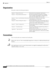
... for adapter 6 Product documentation 7 Cisco SDM software CD 8 Swivel-mount dipole antenna (wireless router models only) Preparing for connection to Ethernet ports. If you ordered a power-over-Ethernet (PoE) module, remove the PoE, its power adapter, and its power cord from the box. Remove the cables and product documentation from your service provider. If you plan...
... for adapter 6 Product documentation 7 Cisco SDM software CD 8 Swivel-mount dipole antenna (wireless router models only) Preparing for connection to Ethernet ports. If you ordered a power-over-Ethernet (PoE) module, remove the PoE, its power adapter, and its power cord from the box. Remove the cables and product documentation from your service provider. If you plan...

Hardware Installation Guide
Page 38
Cisco 850 Series and Cisco 870 Series Access Routers Hardware Installation Guide 2-6 OL-5331-01 Read the safety warnings (the "Safety Warnings and Guidelines" section) and information about preventing damage to the router (the "Preventing Damage to Do Next Mount the router properly by following the instructions in Chapter 3, "Router and PoE Module Mounting Procedures." What to the Router" section). What to Do Next Chapter 2 Preinstallation Information Step 9 Step 10 If you plan to use the cable-lock feature, provide a Kensington or equivalent locking cable.
Cisco 850 Series and Cisco 870 Series Access Routers Hardware Installation Guide 2-6 OL-5331-01 Read the safety warnings (the "Safety Warnings and Guidelines" section) and information about preventing damage to the router (the "Preventing Damage to Do Next Mount the router properly by following the instructions in Chapter 3, "Router and PoE Module Mounting Procedures." What to the Router" section). What to Do Next Chapter 2 Preinstallation Information Step 9 Step 10 If you plan to use the cable-lock feature, provide a Kensington or equivalent locking cable.

Hardware Installation Guide
Page 39
... Mounting Procedures This chapter describes the procedures for mounting the following routers and the power-over-Ethernet (PoE) module: • Cisco 851 and Cisco 871 routers • Cisco 857 and Cisco 877 routers • Cisco 876 router • Cisco 878 router This chapter contains the following sections: • Connecting Antennas to the Wireless Router, page 3-1 • Mounting on a Table, page 3-1 • Mounting on a Wall...
... Mounting Procedures This chapter describes the procedures for mounting the following routers and the power-over-Ethernet (PoE) module: • Cisco 851 and Cisco 871 routers • Cisco 857 and Cisco 877 routers • Cisco 876 router • Cisco 878 router This chapter contains the following sections: • Connecting Antennas to the Wireless Router, page 3-1 • Mounting on a Table, page 3-1 • Mounting on a Wall...

Hardware Installation Guide
Page 40
...manufacturer. Cisco 850 Series and Cisco 870 Series Access Routers Hardware Installation Guide 3-2 OL-5331-01 Guidelines for Wall Mounting You should meet the following guidelines when you mount the router or PoE module on a wall: • Mount the router with the Ethernet cables (To ROUTER side) ...strain on a wall. Mounting on a Wall Chapter 3 Router and PoE Module Mounting Procedures Mounting on a Wall This section provides information for mounting the router and the PoE module on the power adapter cable could pull the router from the connector on a horizontal surface such as the ...
...manufacturer. Cisco 850 Series and Cisco 870 Series Access Routers Hardware Installation Guide 3-2 OL-5331-01 Guidelines for Wall Mounting You should meet the following guidelines when you mount the router or PoE module on a wall: • Mount the router with the Ethernet cables (To ROUTER side) ...strain on a wall. Mounting on a Wall Chapter 3 Router and PoE Module Mounting Procedures Mounting on a Wall This section provides information for mounting the router and the PoE module on the power adapter cable could pull the router from the connector on a horizontal surface such as the ...

Hardware Installation Guide
Page 41
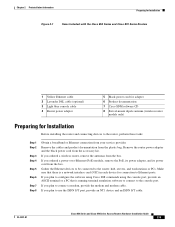
OL-5331-01 Cisco 850 Series and Cisco 870 Series Access Routers Hardware Installation Guide 3-3 Chapter 3 Router and PoE Module Mounting Procedures Figure 3-1 Mounting Brackets on the Bottom of the Router 1 2 Mounting on a Wall 3 127042 1 Distance between two top mounting brackets 3 Vertical distance between the top mounting (near the front panel) brackets and the bottom bracket 2 Midpoint between the two top mounting brackets (near the front panel) Figure 3-2 shows the locations of the mounting screws and the router mounting brackets, and the placement of the power adapter.
OL-5331-01 Cisco 850 Series and Cisco 870 Series Access Routers Hardware Installation Guide 3-3 Chapter 3 Router and PoE Module Mounting Procedures Figure 3-1 Mounting Brackets on the Bottom of the Router 1 2 Mounting on a Wall 3 127042 1 Distance between two top mounting brackets 3 Vertical distance between the top mounting (near the front panel) brackets and the bottom bracket 2 Midpoint between the two top mounting brackets (near the front panel) Figure 3-2 shows the locations of the mounting screws and the router mounting brackets, and the placement of the power adapter.

Hardware Installation Guide
Page 42
...-5331-01 screws 5 Maximum distance between the router and the power adapter (6 ft. [1.8 m]) 2 Distance between the screw head and the wall (1/8 in . Mounting on a Wall Figure 3-2 Mounting the Router on a Wall 2 1 Chapter 3 Router and PoE Module Mounting Procedures 1 3 1 7 OK 0 ET1HERNE2T LAN 3 LNK RXWDAN TXD PPP VPN OK WLDAATNA CISCO 800 SERIES 4 5 121714 6 1 Three number-six...
...-5331-01 screws 5 Maximum distance between the router and the power adapter (6 ft. [1.8 m]) 2 Distance between the screw head and the wall (1/8 in . Mounting on a Wall Figure 3-2 Mounting the Router on a Wall 2 1 Chapter 3 Router and PoE Module Mounting Procedures 1 3 1 7 OK 0 ET1HERNE2T LAN 3 LNK RXWDAN TXD PPP VPN OK WLDAATNA CISCO 800 SERIES 4 5 121714 6 1 Three number-six...

Hardware Installation Guide
Page 43
... top mounting screws. Figure 3-3 shows the location of the mounting brackets on which you wish to mount the router. Chapter 3 Router and PoE Module Mounting Procedures Mounting on a Wall Perform the following steps to mount the router on a wall: Step 1 Step 2 Step 3 Step 4 Step 5 Step 6 Step 7 Select a ... the PoE module. Drill two holes for the mounting screws, one of the screw holes to determine the midpoint between the screw head and the wall for the bottom mounting screw, and then drill a hole. OL-5331-01 Cisco 850 Series and Cisco 870 Series Access Routers Hardware Installation...
... top mounting screws. Figure 3-3 shows the location of the mounting brackets on which you wish to mount the router. Chapter 3 Router and PoE Module Mounting Procedures Mounting on a Wall Perform the following steps to mount the router on a wall: Step 1 Step 2 Step 3 Step 4 Step 5 Step 6 Step 7 Select a ... the PoE module. Drill two holes for the mounting screws, one of the screw holes to determine the midpoint between the screw head and the wall for the bottom mounting screw, and then drill a hole. OL-5331-01 Cisco 850 Series and Cisco 870 Series Access Routers Hardware Installation...

Hardware Installation Guide
Page 44
...." Anchor the screws into the latches of the mounting brackets. Cisco 850 Series and Cisco 870 Series Access Routers Hardware Installation Guide 3-6 OL-5331-01 What to Do Next Chapter 3 Router and PoE Module Mounting Procedures Figure 3-3 Mounting Brackets on the Bottom Panel of the PoE Module 1 2 127092 1 1 Mounting brackets 2 Distance between the screw head and...
...." Anchor the screws into the latches of the mounting brackets. Cisco 850 Series and Cisco 870 Series Access Routers Hardware Installation Guide 3-6 OL-5331-01 What to Do Next Chapter 3 Router and PoE Module Mounting Procedures Figure 3-3 Mounting Brackets on the Bottom Panel of the PoE Module 1 2 127092 1 1 Mounting brackets 2 Distance between the screw head and...

Hardware Installation Guide
Page 45
... contains the following sections: • Cabling for Cisco 851, Cisco 857, Cisco 871, Cisco 876, Cisco 877, and Cisco 878 routers. See Chapter 3, "Router and PoE Module Mounting Procedures." CH A P T E R 4 Router Cabling Procedures This chapter describes the cabling procedures for Nonwireless Routers, page 4-2 • Typical Installations, page 4-2 • Connecting the Radio Antennas to the Wireless Router, page 4-6 • Connecting the Power-over -Ethernet...
... contains the following sections: • Cabling for Cisco 851, Cisco 857, Cisco 871, Cisco 876, Cisco 877, and Cisco 878 routers. See Chapter 3, "Router and PoE Module Mounting Procedures." CH A P T E R 4 Router Cabling Procedures This chapter describes the cabling procedures for Nonwireless Routers, page 4-2 • Typical Installations, page 4-2 • Connecting the Radio Antennas to the Wireless Router, page 4-6 • Connecting the Power-over -Ethernet...

Hardware Installation Guide
Page 51
...-over -Ethernet Module to the Router 2 1 1 LEFT 0 5 Cisco 871W LAN FE0 FE1 FE2 FE3 0 1 2 3 To LAN WAN FE4 RESET CONSOLE AUX +5,+12 VDC 3 PWR 4 RIGHT / PRIMARY 121035 1 Router 4 PoE module 2 Router Ethernet ports 5 Plastic cable guard 3 Ethernet cables connecting the PoE module to the router After you connect the PoE module to the router, connect the Ethernet devices to the...
...-over -Ethernet Module to the Router 2 1 1 LEFT 0 5 Cisco 871W LAN FE0 FE1 FE2 FE3 0 1 2 3 To LAN WAN FE4 RESET CONSOLE AUX +5,+12 VDC 3 PWR 4 RIGHT / PRIMARY 121035 1 Router 4 PoE module 2 Router Ethernet ports 5 Plastic cable guard 3 Ethernet cables connecting the PoE module to the router After you connect the PoE module to the router, connect the Ethernet devices to the...


