
User Guide
Page 1
... Fax ( ) E-mail Can we rate in the following three product features the most: Document Information Document Title: Catalyst 8540 Chassis Installation Guide Part Number: 78-6134-03 On a scale of 1-5 (5 being the best) please let us know how...method do you further concerning our documentation? Cisco Reader Comment Card General Information 1 Years of networking experience Years of experience with Cisco products 2 I have these network types: Other: LAN Backbone WAN 3 I have these Cisco products: Other: Specify model(s) Switches Routers 4 I perform these types of tasks: ...
... Fax ( ) E-mail Can we rate in the following three product features the most: Document Information Document Title: Catalyst 8540 Chassis Installation Guide Part Number: 78-6134-03 On a scale of 1-5 (5 being the best) please let us know how...method do you further concerning our documentation? Cisco Reader Comment Card General Information 1 Years of networking experience Years of experience with Cisco products 2 I have these network types: Other: LAN Backbone WAN 3 I have these Cisco products: Other: Specify model(s) Switches Routers 4 I perform these types of tasks: ...
User Guide
Page 7
1 C H A P T E R Preface vii Audience vii New and Changed Information vii Organization viii Conventions viii Related Documentation xi Obtaining Documentation xiii World Wide Web xiii Documentation CD-ROM xiii Ordering Documentation xiv Obtaining Technical Assistance xiv Cisco Connection Online xiv Technical Assistance Center xv Documentation Feedback xvi Product Overview 1-1 Interface Modules and Port Adapters 1-2 Route Processors 1-3 Switch Modules 1-3 Power Supplies 1-4 Fan Assembly 1-5 CONTENTS 78-6134-03 Catalyst 8540 Chassis Installation Guide v
1 C H A P T E R Preface vii Audience vii New and Changed Information vii Organization viii Conventions viii Related Documentation xi Obtaining Documentation xiii World Wide Web xiii Documentation CD-ROM xiii Ordering Documentation xiv Obtaining Technical Assistance xiv Cisco Connection Online xiv Technical Assistance Center xv Documentation Feedback xvi Product Overview 1-1 Interface Modules and Port Adapters 1-2 Route Processors 1-3 Switch Modules 1-3 Power Supplies 1-4 Fan Assembly 1-5 CONTENTS 78-6134-03 Catalyst 8540 Chassis Installation Guide v

User Guide
Page 9
... in the "Route Processors" section on page 1-3 and the "Switch Modules" section on page 1-3. 78-6134-03 Catalyst 8540 Chassis Installation Guide vii New and Changed Information Feature Redundancy Description The Catalyst 8540 chassis supports fault tolerance by allowing a secondary (or redundant) route... processor and switch module to be familiar with electronic circuitry and wiring practices and have some ...
... in the "Route Processors" section on page 1-3 and the "Switch Modules" section on page 1-3. 78-6134-03 Catalyst 8540 Chassis Installation Guide vii New and Changed Information Feature Redundancy Description The Catalyst 8540 chassis supports fault tolerance by allowing a secondary (or redundant) route... processor and switch module to be familiar with electronic circuitry and wiring practices and have some ...
User Guide
Page 14
Related Documentation Preface • Cisco Interactive Quick Start Guides: Catalyst 8540 http://www.cisco.com/mm/quickstart/ • Catalyst 8540 CSR Route Processor and Interface Module Installation Guide • Layer 3 Switching Software Feature and Configuration Guide Catalyst 8540 Chassis Installation Guide xii 78-6134-03
Related Documentation Preface • Cisco Interactive Quick Start Guides: Catalyst 8540 http://www.cisco.com/mm/quickstart/ • Catalyst 8540 CSR Route Processor and Interface Module Installation Guide • Layer 3 Switching Software Feature and Configuration Guide Catalyst 8540 Chassis Installation Guide xii 78-6134-03
User Guide
Page 15
... • Catalyst 8540 Hardware Quick Reference • Cisco Interactive Quick Start Guides: Catalyst 8540 http://www.cisco.com/mm/quickstart/ • Processor Installation Guide • ATM Port Adapter and Interface Module Installation Guide • Guide to ATM Technology • ATM Switch Router Quick Software Configuration Guide • ATM Switch Router Software Configuration Guide • ATM Switch Router Command Reference • ATM Switch Router Troubleshooting...
... • Catalyst 8540 Hardware Quick Reference • Cisco Interactive Quick Start Guides: Catalyst 8540 http://www.cisco.com/mm/quickstart/ • Processor Installation Guide • ATM Port Adapter and Interface Module Installation Guide • Guide to ATM Technology • ATM Switch Router Quick Software Configuration Guide • ATM Switch Router Software Configuration Guide • ATM Switch Router Command Reference • ATM Switch Router Troubleshooting...
User Guide
Page 19
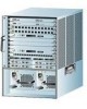
.... Refer to the Catalyst 8540 CSR Route Processor and Interface Module Installation Guide for detailed information about the Catalyst 8540 CSR hardware components and...Catalyst 8540 MSR hardware components and installation. 78-6134-03 Catalyst 8540 Chassis Installation Guide 1-1 CH A P T E R 1 Product Overview This chapter describes the Catalyst 8540, a 13-slot, modular chassis, and provides an overview of a fully populated Catalyst 8540 chassis. The following sections describe the chassis components: • Interface Modules and Port Adapters • Route Processors • Switch...
.... Refer to the Catalyst 8540 CSR Route Processor and Interface Module Installation Guide for detailed information about the Catalyst 8540 CSR hardware components and...Catalyst 8540 MSR hardware components and installation. 78-6134-03 Catalyst 8540 Chassis Installation Guide 1-1 CH A P T E R 1 Product Overview This chapter describes the Catalyst 8540, a 13-slot, modular chassis, and provides an overview of a fully populated Catalyst 8540 chassis. The following sections describe the chassis components: • Interface Modules and Port Adapters • Route Processors • Switch...

User Guide
Page 20
... 1-1 Catalyst 8540 Chassis Slots 0-3: Interface modules Slot 4: Route processor Slots 5-7: Switch modules Slot 8: Redundant route processor Slots 9-12: Interface modules Chapter 1 Product Overview 32600 INPUT FAN OUTPUT OK OK FAIL INPUT FAN OK OK Power supply 0 Power supply 1 Interface Modules and Port Adapters The Catalyst 8540 interface ...and slots 9 through 7 are reserved for route processors and slots 5 through 12 of the chassis. Slots 4 and 8 are reserved for switch modules. You can install up to network services. Catalyst 8540 Chassis Installation Guide 1-2 78-6134-03
... 1-1 Catalyst 8540 Chassis Slots 0-3: Interface modules Slot 4: Route processor Slots 5-7: Switch modules Slot 8: Redundant route processor Slots 9-12: Interface modules Chapter 1 Product Overview 32600 INPUT FAN OUTPUT OK OK FAIL INPUT FAN OK OK Power supply 0 Power supply 1 Interface Modules and Port Adapters The Catalyst 8540 interface ...and slots 9 through 7 are reserved for route processors and slots 5 through 12 of the chassis. Slots 4 and 8 are reserved for switch modules. You can install up to network services. Catalyst 8540 Chassis Installation Guide 1-2 78-6134-03
User Guide
Page 21
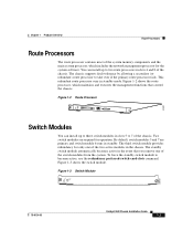
... 1-3 Switch Module STATUS ASCTATNIVDEBY SWITCH PROCESSOR 32602 78-6134-03 Catalyst 8540 Chassis Installation Guide 1-3 Two switch modules are primary and switch module 6 runs in the chassis. The standby switch module automatically becomes active in the event that control the chassis. Figure 1-3 shows the switch module.... functions that you remove one of the two active modules in standby. By default, switch modules 5 and 7 are required for operation. The third switch module provides redundancy for the system software. Figure 1-2 shows the route processor, which includes...
... 1-3 Switch Module STATUS ASCTATNIVDEBY SWITCH PROCESSOR 32602 78-6134-03 Catalyst 8540 Chassis Installation Guide 1-3 Two switch modules are primary and switch module 6 runs in the chassis. The standby switch module automatically becomes active in the event that control the chassis. Figure 1-3 shows the switch module.... functions that you remove one of the two active modules in standby. By default, switch modules 5 and 7 are required for operation. The third switch module provides redundancy for the system software. Figure 1-2 shows the route processor, which includes...
User Guide
Page 22
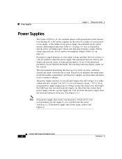
... | ). If an internal power supply temperature or voltage reaches the alarm level, the Output Fail LED may turn the power switch on the console. Catalyst 8540 Chassis Installation Guide 1-4 78-6134-03 Before connecting each unit, note its power consumption rating in Table A-1 on page A-1 lists...monitor the system. Power Supplies Chapter 1 Product Overview Power Supplies The Catalyst 8540 is either within the power supply. Each power supply monitors its own internal temperature and voltages. It is a 13-slot, modular chassis with optional dual, fault-tolerant, load-sharing AC or DC ...
... | ). If an internal power supply temperature or voltage reaches the alarm level, the Output Fail LED may turn the power switch on the console. Catalyst 8540 Chassis Installation Guide 1-4 78-6134-03 Before connecting each unit, note its power consumption rating in Table A-1 on page A-1 lists...monitor the system. Power Supplies Chapter 1 Product Overview Power Supplies The Catalyst 8540 is either within the power supply. Each power supply monitors its own internal temperature and voltages. It is a 13-slot, modular chassis with optional dual, fault-tolerant, load-sharing AC or DC ...
User Guide
Page 26
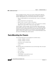
...need, such as transceivers, modems, channel service units (CSUs), or data service units (DSUs) All port adapters, interface modules, and switch modules ship installed in the accessory kit that ships with your site for network connections to the chassis: • Type of cabling required ...8226; Two L brackets • Two cable guides • 18 M3 Phillips countersunk-head screws • 12 M3 Phillips pan-head screws Catalyst 8540 Chassis Installation Guide 2-2 78-6134-03 Refer to the Processor Installation Guide and the ATM Port Adapter and Interface Module Installation Guide for detailed ...
...need, such as transceivers, modems, channel service units (CSUs), or data service units (DSUs) All port adapters, interface modules, and switch modules ship installed in the accessory kit that ships with your site for network connections to the chassis: • Type of cabling required ...8226; Two L brackets • Two cable guides • 18 M3 Phillips countersunk-head screws • 12 M3 Phillips pan-head screws Catalyst 8540 Chassis Installation Guide 2-2 78-6134-03 Refer to the Processor Installation Guide and the ATM Port Adapter and Interface Module Installation Guide for detailed ...

User Guide
Page 34
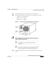
... the terminal block cover. (See Figure 2-6.) Figure 2-6 DC Power Supply (Terminal Block Cover Shown) 17116 Terminal block cover Power switch o INPUT OK FAN OUTPUT OK FAIL LEDs Captive screw 2-10 Catalyst 8540 Chassis Installation Guide 78-6134-03 Remove the terminal block cover by checking the power supply LEDs. Connecting the DC Power...
... the terminal block cover. (See Figure 2-6.) Figure 2-6 DC Power Supply (Terminal Block Cover Shown) 17116 Terminal block cover Power switch o INPUT OK FAN OUTPUT OK FAIL LEDs Captive screw 2-10 Catalyst 8540 Chassis Installation Guide 78-6134-03 Remove the terminal block cover by checking the power supply LEDs. Connecting the DC Power...
User Guide
Page 35
Note Route the wires from the top of the terminal block so that all wire connections are secure. 78-6134-03 Catalyst 8540 Chassis Installation Guide 2-11 Chapter 2 Installing the Chassis Connecting Power to the Chassis Step 4 Step 5 Attach the appropriate lugs to the DC-input ...of the terminal block as follows: • Ground wire to ground terminal • Return wire to "+" terminal • Battery wire to the chassis power switch. Note Use 8 AWG, 90° , copper conductor for the above connections. Step 6 Reinstall the terminal block cover after ensuring that you do not ...
Note Route the wires from the top of the terminal block so that all wire connections are secure. 78-6134-03 Catalyst 8540 Chassis Installation Guide 2-11 Chapter 2 Installing the Chassis Connecting Power to the Chassis Step 4 Step 5 Attach the appropriate lugs to the DC-input ...of the terminal block as follows: • Ground wire to ground terminal • Return wire to "+" terminal • Battery wire to the chassis power switch. Note Use 8 AWG, 90° , copper conductor for the above connections. Step 6 Reinstall the terminal block cover after ensuring that you do not ...
User Guide
Page 36
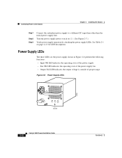
Turn the power supply power switch on page 2-13 for LED descriptions. See Table 2-1 on ( | ). (See Figure 2-7.) Verify power supply operation by checking the power supply LEDs. Power Supply LEDs The ...; Output Fail LED indicates the output voltage is outside of proper range Figure 2-8 Power Supply LEDs 32599 INPUT OK FAN OUTPUT OK FAIL LEDs 2-12 Catalyst 8540 Chassis Installation Guide 78-6134-03 Connecting Power to the Chassis Chapter 2 Installing the Chassis Step 7 Step 8 Step 9 Connect the redundant power supply to a different...
Turn the power supply power switch on page 2-13 for LED descriptions. See Table 2-1 on ( | ). (See Figure 2-7.) Verify power supply operation by checking the power supply LEDs. Power Supply LEDs The ...; Output Fail LED indicates the output voltage is outside of proper range Figure 2-8 Power Supply LEDs 32599 INPUT OK FAN OUTPUT OK FAIL LEDs 2-12 Catalyst 8540 Chassis Installation Guide 78-6134-03 Connecting Power to the Chassis Chapter 2 Installing the Chassis Step 7 Step 8 Step 9 Connect the redundant power supply to a different...
User Guide
Page 41
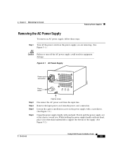
Figure 3-1 AC Power Supply Power cord connection 33014 Power switch INPUT OK FAN OUTPUT OK FAIL Step 2 Step 3 Step 4 Step 5 Captive screw Disconnect the AC power cord ...hand underneath to support the bottom of the chassis toward you are removing. (See Figure 3-1.) Caution Failure to turn off the power switch on the power supply with a screwdriver. (See Figure 3-1.) Grasp the power supply handle with one hand. Remove the input power ... power supply you . Slowly pull the power supply out of the supply. (See Figure 3-2.) 78-6134-03 Catalyst 8540 Chassis Installation Guide 3-3
Figure 3-1 AC Power Supply Power cord connection 33014 Power switch INPUT OK FAN OUTPUT OK FAIL Step 2 Step 3 Step 4 Step 5 Captive screw Disconnect the AC power cord ...hand underneath to support the bottom of the chassis toward you are removing. (See Figure 3-1.) Caution Failure to turn off the power switch on the power supply with a screwdriver. (See Figure 3-1.) Grasp the power supply handle with one hand. Remove the input power ... power supply you . Slowly pull the power supply out of the supply. (See Figure 3-2.) 78-6134-03 Catalyst 8540 Chassis Installation Guide 3-3
User Guide
Page 43
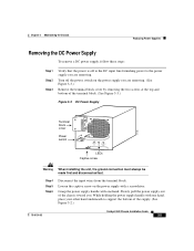
... power to support the bottom of the supply. (See Figure 3-2.) 78-6134-03 Catalyst 8540 Chassis Installation Guide 3-5 Slowly pull the power supply out of the terminal block. (See Figure 3-3.) Figure 3-3 DC Power Supply 17116 Terminal block cover Power switch o INPUT OK FAN OUTPUT OK FAIL LEDs Captive screw Warning When installing the... Supplies Removing the DC Power Supply To remove a DC power supply, follow these steps: Step 1 Step 2 Step 3 Verify that the power is off the power switch on the power supply with a screwdriver.
... power to support the bottom of the supply. (See Figure 3-2.) 78-6134-03 Catalyst 8540 Chassis Installation Guide 3-5 Slowly pull the power supply out of the terminal block. (See Figure 3-3.) Figure 3-3 DC Power Supply 17116 Terminal block cover Power switch o INPUT OK FAN OUTPUT OK FAIL LEDs Captive screw Warning When installing the... Supplies Removing the DC Power Supply To remove a DC power supply, follow these steps: Step 1 Step 2 Step 3 Verify that the power is off the power switch on the power supply with a screwdriver.

User Guide
Page 44
... overtemperature condition. The fan assembly is a single unit that draws in cooling air and distributes it with live voltage at the rear of the bay. Catalyst 8540 Chassis Installation Guide 3-6 78-6134-03 Replacing the Fan Assembly Chapter 3 Maintaining the Chassis Step 7 Install a power supply cover plate over the opening and secure...
... overtemperature condition. The fan assembly is a single unit that draws in cooling air and distributes it with live voltage at the rear of the bay. Catalyst 8540 Chassis Installation Guide 3-6 78-6134-03 Replacing the Fan Assembly Chapter 3 Maintaining the Chassis Step 7 Install a power supply cover plate over the opening and secure...
User Guide
Page 49
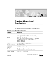
... supply specifications are described in . (20.1 x 18.1 x 38.9 cm) Weight Airflow Chassis only: 70 lb (31.7 kg) Chassis fully configured with 2 route processors, 8 line modules, 3 switch modules, and 2 power supplies:160 lb (72.5 kg) AC power supply: 22 lb DC power supply: 25 lb 200 lfm1 through the system fan assembly...° C) Humidity 10 to 90%, noncondensing, operating 5 to 95%, noncondensing, nonoperating, and storage Altitude, operating -500 to 6562 ft. (-52 to 2000 m) 78-6134-03 Catalyst 8540 Chassis Installation Guide A-1
... supply specifications are described in . (20.1 x 18.1 x 38.9 cm) Weight Airflow Chassis only: 70 lb (31.7 kg) Chassis fully configured with 2 route processors, 8 line modules, 3 switch modules, and 2 power supplies:160 lb (72.5 kg) AC power supply: 22 lb DC power supply: 25 lb 200 lfm1 through the system fan assembly...° C) Humidity 10 to 90%, noncondensing, operating 5 to 95%, noncondensing, nonoperating, and storage Altitude, operating -500 to 6562 ft. (-52 to 2000 m) 78-6134-03 Catalyst 8540 Chassis Installation Guide A-1

User Guide
Page 61
... 1-4 removing 2-7 shutdown (note) 1-4 temperature 1-4 voltage monitoring 1-5 See also AC power See also DC power R rack-mounting equipment 2-2 procedures 2-2 tools 2-2 redundancy description 1-3 power supplies 1-4 route processor 1-3 switch modules 1-3 Catalyst 8540 Chassis Installation Guide 3
... 1-4 removing 2-7 shutdown (note) 1-4 temperature 1-4 voltage monitoring 1-5 See also AC power See also DC power R rack-mounting equipment 2-2 procedures 2-2 tools 2-2 redundancy description 1-3 power supplies 1-4 route processor 1-3 switch modules 1-3 Catalyst 8540 Chassis Installation Guide 3
User Guide
Page 62
... processors description 1-3 redundancy 1-3 related documentation 1-1 slots 1-3 S safety preinstall 2-1, 3-1 warnings B-1 site environment layout 2-1 preparing 2-1 specifications AC power supply A-2 airflow A-1 chassis A-1 DC power supply A-3 switch modules description 1-3 redundancy 1-3 related documentation 1-1 Catalyst 8540 Chassis Installation Guide 4 slots 1-3 T TAC contacts xv description xiv, xv obtaining xiv, xv Technical Assistance Center. See TAC temperature monitoring 1-5 power supplies 1-4 specifications...
... processors description 1-3 redundancy 1-3 related documentation 1-1 slots 1-3 S safety preinstall 2-1, 3-1 warnings B-1 site environment layout 2-1 preparing 2-1 specifications AC power supply A-2 airflow A-1 chassis A-1 DC power supply A-3 switch modules description 1-3 redundancy 1-3 related documentation 1-1 Catalyst 8540 Chassis Installation Guide 4 slots 1-3 T TAC contacts xv description xiv, xv obtaining xiv, xv Technical Assistance Center. See TAC temperature monitoring 1-5 power supplies 1-4 specifications...


