Installation Guide
Page 3
... Web xiii Documentation CD-ROM xiv Ordering Documentation xiv Documentation Feedback xiv Obtaining Technical Assistance xv Cisco.com xv Technical Assistance Center xvi Product Overview 1-1 Warning # 1017 1-2 Cisco 7609 Internet Router 1-4 System Features 1-6 Bandwidth and Port Density 1-6 Redundancy 1-7 Component Hot Swapping 1-8 Cisco 7600 Internet Router Components 1-8 Fan Assembly 1-8 Power Supplies 1-9 Cisco 7609 Internet Router Installation Guide iii
... Web xiii Documentation CD-ROM xiv Ordering Documentation xiv Documentation Feedback xiv Obtaining Technical Assistance xv Cisco.com xv Technical Assistance Center xvi Product Overview 1-1 Warning # 1017 1-2 Cisco 7609 Internet Router 1-4 System Features 1-6 Bandwidth and Port Density 1-6 Redundancy 1-7 Component Hot Swapping 1-8 Cisco 7600 Internet Router Components 1-8 Fan Assembly 1-8 Power Supplies 1-9 Cisco 7609 Internet Router Installation Guide iii
Installation Guide
Page 5
... X OL-5079-04 Troubleshooting 4-1 Getting Started 4-2 Problem Solving to the System Component Level 4-2 Identifying Startup Problems 4-3 Troubleshooting the Power Supply 4-5 Troubleshooting the Fan Assembly 4-6 Troubleshooting Modules 4-6 Contacting Customer Service 4-7 Removal and Replacement Procedures 5-1 Removing and Replacing the Power Supply 5-2 Required Tools 5-2 Removing an AC-Input Power... the Fan Assembly 5-12 Removing the Fan Assembly 5-13 Installing the Fan Assembly 5-14 Checking the Installation 5-15 Technical Specifications A-1 Cisco 7609 Internet Router A-2 Cisco 7609 Internet ...
... X OL-5079-04 Troubleshooting 4-1 Getting Started 4-2 Problem Solving to the System Component Level 4-2 Identifying Startup Problems 4-3 Troubleshooting the Power Supply 4-5 Troubleshooting the Fan Assembly 4-6 Troubleshooting Modules 4-6 Contacting Customer Service 4-7 Removal and Replacement Procedures 5-1 Removing and Replacing the Power Supply 5-2 Required Tools 5-2 Removing an AC-Input Power... the Fan Assembly 5-12 Removing the Fan Assembly 5-13 Installing the Fan Assembly 5-14 Checking the Installation 5-15 Technical Specifications A-1 Cisco 7609 Internet Router A-2 Cisco 7609 Internet ...
Installation Guide
Page 23
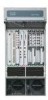
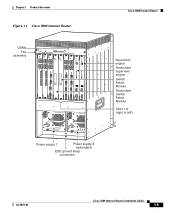
... TX RESET CAARLRAIREMR RX PORT 1 CAARLRAIREMR CAARLRALIRIENMRK RX PORT 2 CAARLRAIREMR RX PORT 3 CAARLRALIRIENMRK RX LINK 4 FAN OUTPUT OK FAIL o o SELECT STATUS ACTIVE NEXT Power supply 1 INPUT OK SELECT STATUS ACTIVE NEXT Chapter 1 Product Overview Figure 1-1 Cisco 7609 Internet Router SWITCH FABRIC MDL WS-C6500-SFM SWITCH FABRIC MDL OSM-40C12-POS-MM STATUS...
... TX RESET CAARLRAIREMR RX PORT 1 CAARLRAIREMR CAARLRALIRIENMRK RX PORT 2 CAARLRAIREMR RX PORT 3 CAARLRALIRIENMRK RX LINK 4 FAN OUTPUT OK FAIL o o SELECT STATUS ACTIVE NEXT Power supply 1 INPUT OK SELECT STATUS ACTIVE NEXT Chapter 1 Product Overview Figure 1-1 Cisco 7609 Internet Router SWITCH FABRIC MDL WS-C6500-SFM SWITCH FABRIC MDL OSM-40C12-POS-MM STATUS...
Installation Guide
Page 24
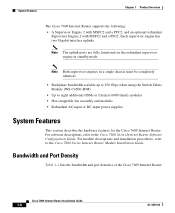
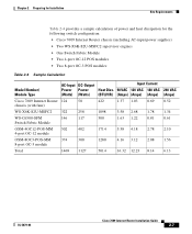
... Internet Router Module Installation Guide. Bandwidth and Port Density Table 1-1 lists the bandwidth and port densities of the Cisco 7609 Internet Router. System Features Chapter 1 Product Overview The Cisco 7609 Internet Router supports the following: • A Supervisor Engine 2 with MSFC2 and a PFC2, and an optional...SFM) • Up to eight additional OSMs or Catalyst 6000 family modules • Hot-swappable fan assembly and modules • Redundant AC-input or DC-input power supplies System Features This section describes the hardware features for the Cisco 7609 Internet Router.
... Internet Router Module Installation Guide. Bandwidth and Port Density Table 1-1 lists the bandwidth and port densities of the Cisco 7609 Internet Router. System Features Chapter 1 Product Overview The Cisco 7609 Internet Router supports the following: • A Supervisor Engine 2 with MSFC2 and a PFC2, and an optional...SFM) • Up to eight additional OSMs or Catalyst 6000 family modules • Hot-swappable fan assembly and modules • Redundant AC-input or DC-input power supplies System Features This section describes the hardware features for the Cisco 7609 Internet Router.
Installation Guide
Page 25
... fully redundant, AC-input or DC-input, load-sharing power supplies Note In certain configurations, the power supplies are not fully redundant. • A hot-swappable fan assembly containing multiple fans • Redundant backplane-mounted clock modules • Redundant backplane-mounted voltage termination (VTT) modules OL-5079-04 Cisco 7609 Internet Router Installation Guide 1-7
... fully redundant, AC-input or DC-input, load-sharing power supplies Note In certain configurations, the power supplies are not fully redundant. • A hot-swappable fan assembly containing multiple fans • Redundant backplane-mounted clock modules • Redundant backplane-mounted voltage termination (VTT) modules OL-5079-04 Cisco 7609 Internet Router Installation Guide 1-7
Installation Guide
Page 26
...the supervisor engine and the switching modules. Fan Assembly The system fan assembly provides cooling air for the Cisco 7609 Internet Router. If the air temperature exceeds a preset threshold, the environmental monitor displays warning messages. Cisco 7609 Internet Router Installation Guide 1-8 OL-5079...-04 Sensors on environmental monitoring. If an individual fan within the assembly fails, the FAN STATUS LED turns red. Note Refer to shut down. ...
...the supervisor engine and the switching modules. Fan Assembly The system fan assembly provides cooling air for the Cisco 7609 Internet Router. If the air temperature exceeds a preset threshold, the environmental monitor displays warning messages. Cisco 7609 Internet Router Installation Guide 1-8 OL-5079...-04 Sensors on environmental monitoring. If an individual fan within the assembly fails, the FAN STATUS LED turns red. Note Refer to shut down. ...
Installation Guide
Page 27
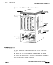
... 2 LINK 8 Module air exhaust (3x) Module air inlet Power supply air exhaust 30697 Power supply air inlet o o INPUT OK FAN OUTPUT OK FAIL INPUT OK FAN OUTPUT OK FAIL Power Supplies The Cisco 7609 Internet Router power supplies are available in two power ratings: • 2500W-AC and DC input (WS-CAC-2500W and...
... 2 LINK 8 Module air exhaust (3x) Module air inlet Power supply air exhaust 30697 Power supply air inlet o o INPUT OK FAN OUTPUT OK FAIL INPUT OK FAN OUTPUT OK FAIL Power Supplies The Cisco 7609 Internet Router power supplies are available in two power ratings: • 2500W-AC and DC input (WS-CAC-2500W and...
Installation Guide
Page 28
...connection Cable retention device Power switch I 0 INPUT OK FAN OUTPUT OK FAIL Status LEDs Captive installation screw 1-10 Cisco 7609 Internet Router Installation Guide 16029 OL-5079-04 When power is not shown in a fully populated Cisco 7609 Internet Router. You can connect the DC-input power supply... and DC-input power supplies support redundancy. The AC-input power supply (see Appendix A, "Technical Specifications." Cisco 7600 Internet Router Components Chapter 1 Product Overview The Cisco 7609 Internet Router supports redundant AC-input and DC-input power supplies.
...connection Cable retention device Power switch I 0 INPUT OK FAN OUTPUT OK FAIL Status LEDs Captive installation screw 1-10 Cisco 7609 Internet Router Installation Guide 16029 OL-5079-04 When power is not shown in a fully populated Cisco 7609 Internet Router. You can connect the DC-input power supply... and DC-input power supplies support redundancy. The AC-input power supply (see Appendix A, "Technical Specifications." Cisco 7600 Internet Router Components Chapter 1 Product Overview The Cisco 7609 Internet Router supports redundant AC-input and DC-input power supplies.
Installation Guide
Page 29
Chapter 1 Product Overview Cisco 7600 Internet Router Components Figure 1-4 DC-Input Power Supply Terminal block cover 16028 DC power cable terminal block Power switch I 0 INPUT FAN OUTPUT OK OK FAIL Status LEDs Captive installation screw Load Sharing When you must install two ...power supply enables load sharing and fault tolerance automatically; Note For proper load-sharing operation in the chassis. OL-5079-04 Cisco 7609 Internet Router Installation Guide 1-11 For information about the power management feature and individual module power consumption, refer to maintain ...
Chapter 1 Product Overview Cisco 7600 Internet Router Components Figure 1-4 DC-Input Power Supply Terminal block cover 16028 DC power cable terminal block Power switch I 0 INPUT FAN OUTPUT OK OK FAIL Status LEDs Captive installation screw Load Sharing When you must install two ...power supply enables load sharing and fault tolerance automatically; Note For proper load-sharing operation in the chassis. OL-5079-04 Cisco 7609 Internet Router Installation Guide 1-11 For information about the power management feature and individual module power consumption, refer to maintain ...
Installation Guide
Page 30
The power supplies monitor their own internal temperature and voltages. Table 1-2 Power Supply Front Panel LEDs LED INPUT OK FAN OK OUTPUT FAIL Description AC-input power supplies: • Green when the input voltage is OK (85 VAC or greater) • Off when the...to prevent damage. Substantial overvoltage conditions can lead to a power supply shutdown. For more of the DC-output voltages of the power supply 1-12 Cisco 7609 Internet Router Installation Guide OL-5079-04 The power supply front panel LEDs are described in Table 1-2. In the event of excessive internal temperature, the...
The power supplies monitor their own internal temperature and voltages. Table 1-2 Power Supply Front Panel LEDs LED INPUT OK FAN OK OUTPUT FAIL Description AC-input power supplies: • Green when the input voltage is OK (85 VAC or greater) • Off when the...to prevent damage. Substantial overvoltage conditions can lead to a power supply shutdown. For more of the DC-output voltages of the power supply 1-12 Cisco 7609 Internet Router Installation Guide OL-5079-04 The power supply front panel LEDs are described in Table 1-2. In the event of excessive internal temperature, the...
Installation Guide
Page 31
An air dam keeps the airflow separate from the rest of the fan (power-input end) and exits through the back. To replace a power supply, see the "Removing and Replacing the Power Supply" section on page 5-2. OL-5079-04 Cisco 7609 Internet Router Installation Guide 1-13 Chapter 1 Product Overview Cisco 7600 Internet Router Components Power Supply Fan Assembly The power supplies have a built-in fan; air enters the front of the chassis, which is cooled by the system fan assembly.
An air dam keeps the airflow separate from the rest of the fan (power-input end) and exits through the back. To replace a power supply, see the "Removing and Replacing the Power Supply" section on page 5-2. OL-5079-04 Cisco 7609 Internet Router Installation Guide 1-13 Chapter 1 Product Overview Cisco 7600 Internet Router Components Power Supply Fan Assembly The power supplies have a built-in fan; air enters the front of the chassis, which is cooled by the system fan assembly.

Installation Guide
Page 35
... Input Current Power Power Heat Diss. 90 VAC 120 VAC 180 VAC 240 VAC (Watts) (Watts) (BTU/HR) (Amps) (Amps) (Amps) (Amps) Cisco 7609 Internet Router 155 75 chassis (with fans) 530 1.71 1.29 0.86 0.65 WS-X6K-S2U-MSFC2 181.65 129 549 1.79 1.34 0.89 0.67 OSM-2OC12-POS-MM, 176... -SI+ OC-12 ATM, 2-port OSM-1OC48-POS-SS, -SI, 223 179 762 2.48 1.86 1.24 0.93 -SL OC-48 POS, 1-port OL-5079-04 Cisco 7609 Internet Router Installation Guide 2-3
... Input Current Power Power Heat Diss. 90 VAC 120 VAC 180 VAC 240 VAC (Watts) (Watts) (BTU/HR) (Amps) (Amps) (Amps) (Amps) Cisco 7609 Internet Router 155 75 chassis (with fans) 530 1.71 1.29 0.86 0.65 WS-X6K-S2U-MSFC2 181.65 129 549 1.79 1.34 0.89 0.67 OSM-2OC12-POS-MM, 176... -SI+ OC-12 ATM, 2-port OSM-1OC48-POS-SS, -SI, 223 179 762 2.48 1.86 1.24 0.93 -SL OC-48 POS, 1-port OL-5079-04 Cisco 7609 Internet Router Installation Guide 2-3
Installation Guide
Page 39
Chapter 2 Preparing for Installation Site Requirements Table 2-4 provides a sample calculation of power and heat dissipation for the following switch configuration: • Cisco 7609 Internet Router chassis (including AC-input power supplies) • Two WS-X6K-S2U-MSFC2 supervisor engines • One Switch Fabric Module •...Power Heat Diss. 90 VAC 120 VAC 180 VAC 240 VAC (Watts) (Watts) (BTU/HR) (Amps) (Amps) (Amps) (Amps) Cisco 7609 Internet Router 124 50 chassis (with fans) 422 1.37 1.03 0.69 0.52 WS-X6K-S2U-MSFC2 322 258 1098 3.58 2.68 1.78 1.34 WS-C6500-SFM 146 117 ...
Chapter 2 Preparing for Installation Site Requirements Table 2-4 provides a sample calculation of power and heat dissipation for the following switch configuration: • Cisco 7609 Internet Router chassis (including AC-input power supplies) • Two WS-X6K-S2U-MSFC2 supervisor engines • One Switch Fabric Module •...Power Heat Diss. 90 VAC 120 VAC 180 VAC 240 VAC (Watts) (Watts) (BTU/HR) (Amps) (Amps) (Amps) (Amps) Cisco 7609 Internet Router 124 50 chassis (with fans) 422 1.37 1.03 0.69 0.52 WS-X6K-S2U-MSFC2 322 258 1098 3.58 2.68 1.78 1.34 WS-C6500-SFM 146 117 ...

Installation Guide
Page 51
Cisco 7609 Internet Router Installation Guide 3-7 Installing the Rack-Mount Kit 55839 L bracket SELECT STATUS ACTIVE NEXT SELECT STATUS ACTIVE NEXT Figure 3-3 Attaching L Brackets and Cable Guides ... 2 3 CALARINLRKAIERRM 1 2 3 4 4 RESET 8 PORT OC3 POS MM LINK 1 2 LINK LINK 3 4 LINK 5 6 7 8 OSM-8OC3-POS MM 1 STATUS 2 3 CALARINLRKAIERRM 1 2 3 4 4 RESET 8 PORT OC3 POS MM LINK 1 2 LINK LINK 3 4 LINK 5 6 7 8 FAN STATUS M4 screws Cable guide L bracket Chapter 3 Installing the Cisco 7609 Internet Router OL-5079-04
Cisco 7609 Internet Router Installation Guide 3-7 Installing the Rack-Mount Kit 55839 L bracket SELECT STATUS ACTIVE NEXT SELECT STATUS ACTIVE NEXT Figure 3-3 Attaching L Brackets and Cable Guides ... 2 3 CALARINLRKAIERRM 1 2 3 4 4 RESET 8 PORT OC3 POS MM LINK 1 2 LINK LINK 3 4 LINK 5 6 7 8 OSM-8OC3-POS MM 1 STATUS 2 3 CALARINLRKAIERRM 1 2 3 4 4 RESET 8 PORT OC3 POS MM LINK 1 2 LINK LINK 3 4 LINK 5 6 7 8 FAN STATUS M4 screws Cable guide L bracket Chapter 3 Installing the Cisco 7609 Internet Router OL-5079-04

Installation Guide
Page 53
...that the chassis is installed straight and level. OL-5079-04 Cisco 7609 Internet Router Installation Guide 3-9 Chapter 3 Installing the Cisco 7609 Internet Router Installing the Cisco 7609 Chassis in the Rack Figure 3-4 Installing the Cisco 7609 Chassis in the Rack ACTIVE ACTIVE TX RX TX RX TX ...RX RX RX RX PORT 2 PORT 2 LINK TX TX TX L bracket o o INPUT OK FAN OUTPUT OK FAIL INPUT OK FAN OUTPUT ...
...that the chassis is installed straight and level. OL-5079-04 Cisco 7609 Internet Router Installation Guide 3-9 Chapter 3 Installing the Cisco 7609 Internet Router Installing the Cisco 7609 Chassis in the Rack Figure 3-4 Installing the Cisco 7609 Chassis in the Rack ACTIVE ACTIVE TX RX TX RX TX ...RX RX RX RX PORT 2 PORT 2 LINK TX TX TX L bracket o o INPUT OK FAN OUTPUT OK FAIL INPUT OK FAN OUTPUT ...

Installation Guide
Page 55
...side. Installing the Stabilizer Kit 55841 SELECT STATUS ACTIVE NEXT SELECT STATUS ACTIVE NEXT Chapter 3 Installing the Cisco 7609 Internet Router Figure 3-5 Installing the Stabilizer Brackets WS-X6K-SUP2-2GE STATUSSYSTEMCONSOLPEWR MGRMETSET CONSOLE SUPERVISOR2 CONSOLE PORT ... LINK 3 4 LINK 5 6 7 8 OSM-8OC3-POS MM 1 STATUS 2 3 CALARINLRKAIERRM 1 2 3 4 4 RESET 8 PORT OC3 POS MM LINK 1 2 LINK LINK 3 4 LINK 5 6 7 8 FAN STATUS Step 3 Step 4 Step 5 OL-5079-04 Attach the second stabilizer bracket to the other side of the chassis with eight M4 screws. Lower the...
...side. Installing the Stabilizer Kit 55841 SELECT STATUS ACTIVE NEXT SELECT STATUS ACTIVE NEXT Chapter 3 Installing the Cisco 7609 Internet Router Figure 3-5 Installing the Stabilizer Brackets WS-X6K-SUP2-2GE STATUSSYSTEMCONSOLPEWR MGRMETSET CONSOLE SUPERVISOR2 CONSOLE PORT ... LINK 3 4 LINK 5 6 7 8 OSM-8OC3-POS MM 1 STATUS 2 3 CALARINLRKAIERRM 1 2 3 4 4 RESET 8 PORT OC3 POS MM LINK 1 2 LINK LINK 3 4 LINK 5 6 7 8 FAN STATUS Step 3 Step 4 Step 5 OL-5079-04 Attach the second stabilizer bracket to the other side of the chassis with eight M4 screws. Lower the...
Installation Guide
Page 65
... hazardous voltages and currents inside the chassis; Chapter 3 Installing the Cisco 7609 Internet Router Verifying Cisco 7609 Chassis Installation Verifying Cisco 7609 Chassis Installation After you finish connecting the modules, you need to verify that the modules, power supplies, and fan assembly are tight. To verify the Cisco 7609 chassis installation, perform these steps: Step 1 Step 2 Step 3 Step 4 Verify...
... hazardous voltages and currents inside the chassis; Chapter 3 Installing the Cisco 7609 Internet Router Verifying Cisco 7609 Chassis Installation Verifying Cisco 7609 Chassis Installation After you finish connecting the modules, you need to verify that the modules, power supplies, and fan assembly are tight. To verify the Cisco 7609 chassis installation, perform these steps: Step 1 Step 2 Step 3 Step 4 Verify...

Installation Guide
Page 67
... System Component Level, page 4-2 • Identifying Startup Problems, page 4-3 • Troubleshooting the Power Supply, page 4-5 • Troubleshooting the Fan Assembly, page 4-6 • Troubleshooting Modules, page 4-6 • Contacting Customer Service, page 4-7 If your system has problems starting up, use...include independent reporting of DC-output voltage problems. OL-5079-04 Cisco 7609 Internet Router Installation Guide 4-1 CH A P T E R 4 Troubleshooting Note This document describes the Cisco 7609 Internet Router (OSR-7609) and not the Cisco 7609 Internet Router (CISCO7609).
... System Component Level, page 4-2 • Identifying Startup Problems, page 4-3 • Troubleshooting the Power Supply, page 4-5 • Troubleshooting the Fan Assembly, page 4-6 • Troubleshooting Modules, page 4-6 • Contacting Customer Service, page 4-7 If your system has problems starting up, use...include independent reporting of DC-output voltage problems. OL-5079-04 Cisco 7609 Internet Router Installation Guide 4-1 CH A P T E R 4 Troubleshooting Note This document describes the Cisco 7609 Internet Router (OSR-7609) and not the Cisco 7609 Internet Router (CISCO7609).
Installation Guide
Page 68
... is operating. Problem Solving to the System Component Level The key to success when troubleshooting the system is on. If the FAN Cisco 7609 Internet Router Installation Guide 4-2 OL-5079-04 Getting Started Chapter 4 Troubleshooting Note This chapter covers only the chassis component hardware ... IOS Command Reference publications to determine whether or not it should operate whenever system power is to isolate the problem to the Cisco 7600 Series Internet Router Module Installation Guide. The first step is to compare what the system is operating. • System software...
... is operating. Problem Solving to the System Component Level The key to success when troubleshooting the system is on. If the FAN Cisco 7609 Internet Router Installation Guide 4-2 OL-5079-04 Getting Started Chapter 4 Troubleshooting Note This chapter covers only the chassis component hardware ... IOS Command Reference publications to determine whether or not it should operate whenever system power is to isolate the problem to the Cisco 7600 Series Internet Router Module Installation Guide. The first step is to compare what the system is operating. • System software...
Installation Guide
Page 69
... determine when and where the system failed in the startup sequence. OL-5079-04 Cisco 7609 Internet Router Installation Guide 4-3 Identifying Startup Problems LEDs indicate all system states in the startup sequence. If you can make if the fan assembly does not function properly at initial startup, there are functioning normally and that...
... determine when and where the system failed in the startup sequence. OL-5079-04 Cisco 7609 Internet Router Installation Guide 4-3 Identifying Startup Problems LEDs indicate all system states in the startup sequence. If you can make if the fan assembly does not function properly at initial startup, there are functioning normally and that...
