Installation Guide
Page 2
.... Operation of Cisco and/or its peripheral devices. This equipment has been tested and found to comply with the specifications in part 15 of the television or radio. • Move the equipment farther away from the television or radio. (That is for a Class B digital device in accordance with Cisco's installation instructions, it may cause interference with the instruction manual, may radiate...
.... Operation of Cisco and/or its peripheral devices. This equipment has been tested and found to comply with the specifications in part 15 of the television or radio. • Move the equipment farther away from the television or radio. (That is for a Class B digital device in accordance with Cisco's installation instructions, it may cause interference with the instruction manual, may radiate...
Installation Guide
Page 15
... or password, go to this URL: http://www.cisco.com Technical Assistance Center The Cisco TAC is available to all customers who have a valid Cisco service contract have complete access to the technical support resources on the Cisco TAC website. No workaround is available. • Priority level 1 (P1)-Your production network is not restored quickly. Preface Obtaining Technical Assistance • Download and test software...
... or password, go to this URL: http://www.cisco.com Technical Assistance Center The Cisco TAC is available to all customers who have a valid Cisco service contract have complete access to the technical support resources on the Cisco TAC website. No workaround is available. • Priority level 1 (P1)-Your production network is not restored quickly. Preface Obtaining Technical Assistance • Download and test software...
Installation Guide
Page 20
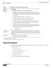
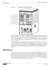
... Ports, page 1-16 Table 1-2 lists the supervisor engine configurations. Management • CLI through the console port or Telnet • Simple Network Management Protocol 1. Onboard bootflash - EEPROM = electrically erasable programmable read-only memory Supervisor Engines This section describes the features on the supervisor engine stores module-specific information, such as the module serial number, part number, controller type, hardware revision, configuration information, and other software or interfaces to manage the file system (such as an I/O device. • Flash file...
... Ports, page 1-16 Table 1-2 lists the supervisor engine configurations. Management • CLI through the console port or Telnet • Simple Network Management Protocol 1. Onboard bootflash - EEPROM = electrically erasable programmable read-only memory Supervisor Engines This section describes the features on the supervisor engine stores module-specific information, such as the module serial number, part number, controller type, hardware revision, configuration information, and other software or interfaces to manage the file system (such as an I/O device. • Flash file...

Installation Guide
Page 31
... Green The disk is no link. Console Port The console port allows you to restart the system. Orange The module is disabled. Orange The port is powering up or has minor hardware problems. Red Major hardware problem. Console Port Mode Switch The console port mode switch allows you to access the system either the console cable and adapters provided with the Cisco 7600 series routers or the console cable provided with the system. Chapter 1 Product Overview Supervisor Engines Table 1-6 Route Switch Processor 720 LEDs (continued) LED...
... Green The disk is no link. Console Port The console port allows you to restart the system. Orange The module is disabled. Orange The port is powering up or has minor hardware problems. Red Major hardware problem. Console Port Mode Switch The console port mode switch allows you to access the system either the console cable and adapters provided with the Cisco 7600 series routers or the console cable provided with the system. Chapter 1 Product Overview Supervisor Engines Table 1-6 Route Switch Processor 720 LEDs (continued) LED...

Installation Guide
Page 32
... connect a terminal, use this mode to connect a modem to the console port using the console cable and DTE adapter (labeled "Terminal") that shipped with the system. • Mode 2-Switch in the out position. You can be used in the chassis. The two 1000BASE-X Gigabit Ethernet uplink ports operate in position (factory default). Note Throughout this publication, the term Flash PC card is used for additional Flash memory. Uplink Ports The supervisor engine provides two Gigabit Ethernet uplink ports...
... connect a terminal, use this mode to connect a modem to the console port using the console cable and DTE adapter (labeled "Terminal") that shipped with the system. • Mode 2-Switch in the out position. You can be used in the chassis. The two 1000BASE-X Gigabit Ethernet uplink ports operate in position (factory default). Note Throughout this publication, the term Flash PC card is used for additional Flash memory. Uplink Ports The supervisor engine provides two Gigabit Ethernet uplink ports...

Installation Guide
Page 48
...-10G3CXL 1 0 ETHERNET SERVICES MODULE CLASS 1 LASER There is one line card Status LED and two port Status LEDs. The port is enabled but there is powered off. STATUS A/L A/L 191217 1-32 Book Title OL-5077-7 Table 1-21 provides LED descriptions. The line card is loading. The line card is online. The port is not enabled by software. The port is enabled and a valid Ethernet link has been established. Ethernet Services 20G Line Cards Chapter 1 Product Overview Table 1-20 Cisco 7600 ES20 Line Card Summary Cisco ES20 Line Card Product Numbers 7600...
...-10G3CXL 1 0 ETHERNET SERVICES MODULE CLASS 1 LASER There is one line card Status LED and two port Status LEDs. The port is enabled but there is powered off. STATUS A/L A/L 191217 1-32 Book Title OL-5077-7 Table 1-21 provides LED descriptions. The line card is loading. The line card is online. The port is not enabled by software. The port is enabled and a valid Ethernet link has been established. Ethernet Services 20G Line Cards Chapter 1 Product Overview Table 1-20 Cisco 7600 ES20 Line Card Summary Cisco ES20 Line Card Product Numbers 7600...

Installation Guide
Page 49
... line cards to be configured for the Cisco 7600 series routers that are the link interface daughter cards that accept small form-factor pluggable (SFP or XFP) optical transceivers. The line card is online. Undefined condition. Additionally, each of 40 Gbps full-duplextraffic forwarding using a fixed port interface design. OL-5077-7 Book Title 1-33 The line card is powered off. Table 1-22 Cisco 7600-ES20-GE Line Card LEDs LED Label STATUS A/L Color Red Green Yellow Off Amber...
... line cards to be configured for the Cisco 7600 series routers that are the link interface daughter cards that accept small form-factor pluggable (SFP or XFP) optical transceivers. The line card is online. Undefined condition. Additionally, each of 40 Gbps full-duplextraffic forwarding using a fixed port interface design. OL-5077-7 Book Title 1-33 The line card is powered off. Table 1-22 Cisco 7600-ES20-GE Line Card LEDs LED Label STATUS A/L Color Red Green Yellow Off Amber...

Installation Guide
Page 53
... the module is not a valid Ethernet link. The line card is required for every port or device that connects to display status information. The physical interface address is loading. The line card is the actual physical location (slot and port) of ports on the rear of the router, as shown in Figure 1-41. (The port numbering convention is the same in the format slot/port number. Chapter 1 Product Overview Port Addresses Table 1-26 LED Label STATUS A/L Cisco...
... the module is not a valid Ethernet link. The line card is required for every port or device that connects to display status information. The physical interface address is loading. The line card is the actual physical location (slot and port) of ports on the rear of the router, as shown in Figure 1-41. (The port numbering convention is the same in the format slot/port number. Chapter 1 Product Overview Port Addresses Table 1-26 LED Label STATUS A/L Cisco...
Installation Guide
Page 54
...1 1 2 LINK 1 LINK 1 LINK 2 LINK 2 3 3 CONSOLE PORT MODE CONSOLE PORT MODE 4 LINK 3 4 LINK 3 LINK 4 LINK 4 RESET RESET LINK CAARLRAIREMR CAARLRAIREMR FAN STATUS Port numbers 1/1 to 1/2 Port numbers 2/1 to 2/2 Port numbers 3/1 to 3/4 Port numbers 4/1 to 4/4 Port numbers 7/1 to 7/4 Port numbers 8/1 to 8/8 Port numbers 9/1 to identify the state (connected or not connected) of each interface in the system, learns the MAC addresses, and then initializes appropriate hardware and data structures. You can also use software commands to reflect the new slot number. Each VLAN in...
...1 1 2 LINK 1 LINK 1 LINK 2 LINK 2 3 3 CONSOLE PORT MODE CONSOLE PORT MODE 4 LINK 3 4 LINK 3 LINK 4 LINK 4 RESET RESET LINK CAARLRAIREMR CAARLRAIREMR FAN STATUS Port numbers 1/1 to 1/2 Port numbers 2/1 to 2/2 Port numbers 3/1 to 3/4 Port numbers 4/1 to 4/4 Port numbers 7/1 to 7/4 Port numbers 8/1 to 8/8 Port numbers 9/1 to identify the state (connected or not connected) of each interface in the system, learns the MAC addresses, and then initializes appropriate hardware and data structures. You can also use software commands to reflect the new slot number. Each VLAN in...
Installation Guide
Page 59
... the chassis and the line card connectors and verify that the module is present, do can result in the Cisco 7600 series routers and contains these sections: • Safety Guidelines, page 2-1 • Limiting Connection Distances, page 2-10 • Determining Cable Distances, page 2-10 • Port Densities, page 2-18 • Software Requirements, page 2-19 This chapter does not contain the instructions to install, replace, or service...
... the chassis and the line card connectors and verify that the module is present, do can result in the Cisco 7600 series routers and contains these sections: • Safety Guidelines, page 2-1 • Limiting Connection Distances, page 2-10 • Determining Cable Distances, page 2-10 • Port Densities, page 2-18 • Software Requirements, page 2-19 This chapter does not contain the instructions to install, replace, or service...
Installation Guide
Page 79
... a Module, page 3-13 • Connecting the Supervisor Engine, page 3-15 • Installing and Removing GBICs, page 3-17 • Using Flash PC Cards, page 3-20 • Verifying the Installation, page 3-22 Required Tools This section describes the requirements and the tools you must install the Cisco 7600 series router chassis and at least one supervisor engine. For information on installing the chassis, refer to the Cisco 7600 Series Router Installation Guide or Cisco 7609 Router Installation Guide. Installing Modules...
... a Module, page 3-13 • Connecting the Supervisor Engine, page 3-15 • Installing and Removing GBICs, page 3-17 • Using Flash PC Cards, page 3-20 • Verifying the Installation, page 3-22 Required Tools This section describes the requirements and the tools you must install the Cisco 7600 series router chassis and at least one supervisor engine. For information on installing the chassis, refer to the Cisco 7600 Series Router Installation Guide or Cisco 7609 Router Installation Guide. Installing Modules...
Installation Guide
Page 91
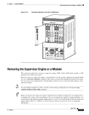
... engine, check the factory default configuration; This step saves time when bringing the module back online. you can reconfigure the supervisor engine manually, or if you previously uploaded the original configuration to a server, you might need to reconfigure the system to your requirements. You can download it from the Cisco 7600 series router. Chapter 3 Installing Modules Removing the Supervisor Engine or a Module Figure 3-10 Installing a Module in the Cisco 7609 Router FAN STATUS LINK 1 8 PORT OC3...
... engine, check the factory default configuration; This step saves time when bringing the module back online. you can reconfigure the supervisor engine manually, or if you previously uploaded the original configuration to a server, you might need to reconfigure the system to your requirements. You can download it from the Cisco 7600 series router. Chapter 3 Installing Modules Removing the Supervisor Engine or a Module Figure 3-10 Installing a Module in the Cisco 7609 Router FAN STATUS LINK 1 8 PORT OC3...

Installation Guide
Page 94
... the terminal must match the default baud rate (9600 baud) of the console port. Connect to the port using a Catalyst 5000 family Supervisor Engine III console cable, place the console port mode switch in the out position. Connecting to the Uplink Ports This section describes how to connect to the supervisor engine uplink ports, perform these steps: Step 1 Step 2 Step 3 Remove the plugs from the Gigabit Interface Converter (GBIC) optical bores...
... the terminal must match the default baud rate (9600 baud) of the console port. Connect to the port using a Catalyst 5000 family Supervisor Engine III console cable, place the console port mode switch in the out position. Connecting to the Uplink Ports This section describes how to connect to the supervisor engine uplink ports, perform these steps: Step 1 Step 2 Step 3 Remove the plugs from the Gigabit Interface Converter (GBIC) optical bores...
Installation Guide
Page 103
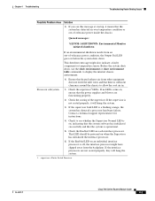
... temperature sensor. Check the Enabled LED on before the system shuts down , use the show environment or show environment table commands to display the internal chassis environment. Check to allow the cool air in. 1. If the supervisor Link LED is sufficient clearance around the chassis to see this message at startup, it will hang the system. 1. Chapter 4 Troubleshooting Troubleshooting Router Booting Issues Possible Problem Area Solution...
... temperature sensor. Check the Enabled LED on before the system shuts down , use the show environment or show environment table commands to display the internal chassis environment. Check to allow the cool air in. 1. If the supervisor Link LED is sufficient clearance around the chassis to see this message at startup, it will hang the system. 1. Chapter 4 Troubleshooting Troubleshooting Router Booting Issues Possible Problem Area Solution...
Installation Guide
Page 104
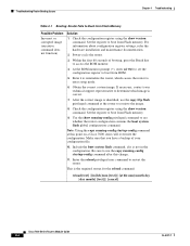
... hardware installation and maintenance documentation. 2. Power-cycle the router. 3. Within the first 60 seconds of your technical support representative to determine which causes the router to enter setup mode. 6. Include the boot system flash command, if it is identified, use the copy running-config startup-config command after this point on a Cisco 7600 series will overwrite the configuration. This is correct. 7. Check the configuration register using the show version command. Troubleshooting Router Booting Issues Chapter 4 Troubleshooting Table 4-1 Booting: Router Fails...
... hardware installation and maintenance documentation. 2. Power-cycle the router. 3. Within the first 60 seconds of your technical support representative to determine which causes the router to enter setup mode. 6. Include the boot system flash command, if it is identified, use the copy running-config startup-config command after this point on a Cisco 7600 series will overwrite the configuration. This is correct. 7. Check the configuration register using the show version command. Troubleshooting Router Booting Issues Chapter 4 Troubleshooting Table 4-1 Booting: Router Fails...
Installation Guide
Page 108
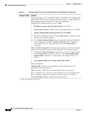
.... TFTP = Trivial File Transfer Protocol Cisco 7600 Series Routers Module Guide 4-8 OL-5077-7 c7600rsp72043-adventerprisek9-mz.122-33.SRE1 writing c7600rsp72043-adventerprisek9-mz.122-33.SRE1 9. The most recent entry goes to the other boot system commands. The device argument is optional, but when it is correct. Troubleshooting Router Booting Issues Chapter 4 Troubleshooting Table 4-2 Booting: Vector Error Occurs When Booting from Flash memory. 10. The required syntax is required. Configure the boot...
.... TFTP = Trivial File Transfer Protocol Cisco 7600 Series Routers Module Guide 4-8 OL-5077-7 c7600rsp72043-adventerprisek9-mz.122-33.SRE1 writing c7600rsp72043-adventerprisek9-mz.122-33.SRE1 9. The most recent entry goes to the other boot system commands. The device argument is optional, but when it is correct. Troubleshooting Router Booting Issues Chapter 4 Troubleshooting Table 4-2 Booting: Vector Error Occurs When Booting from Flash memory. 10. The required syntax is required. Configure the boot...
Installation Guide
Page 113
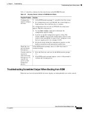
... Monitor Mode Possible Problem Solution Configuration register setting is 0x101, which disables the Break key and forces the router to continue booting. Look for the ROM monitor prompt (>). 2. Console cable was inserted or removed during boot process, or console was pressed during boot process 1. OL-5077-7 Cisco 7600 Series Routers Module Guide 4-13 If a configuration exists in the ROMMON mode. Use the show version command to continue. Troubleshooting Scrambled Output When Booting from ROM When the user boots from...
... Monitor Mode Possible Problem Solution Configuration register setting is 0x101, which disables the Break key and forces the router to continue booting. Look for the ROM monitor prompt (>). 2. Console cable was inserted or removed during boot process, or console was pressed during boot process 1. OL-5077-7 Cisco 7600 Series Routers Module Guide 4-13 If a configuration exists in the ROMMON mode. Use the show version command to continue. Troubleshooting Scrambled Output When Booting from ROM When the user boots from...
Installation Guide
Page 114
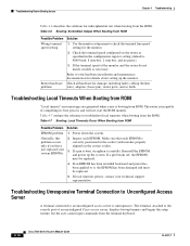
... just replaced your technical support representative. Table 4-7 outlines the solutions to the console port of completing its boot process and will not start the ROM monitor. The terminal, attached to troubleshoot local timeouts when booting from the terminal keyboard. 4-14 Cisco 7600 Series Routers Module Guide OL-5077-7 Troubleshooting Local Timeouts When Booting from ROM "Local timeout" error messages are generated when a user is incapable of an unconfigured Cisco access server...
... just replaced your technical support representative. Table 4-7 outlines the solutions to the console port of completing its boot process and will not start the ROM monitor. The terminal, attached to troubleshoot local timeouts when booting from the terminal keyboard. 4-14 Cisco 7600 Series Routers Module Guide OL-5077-7 Troubleshooting Local Timeouts When Booting from ROM "Local timeout" error messages are generated when a user is incapable of an unconfigured Cisco access server...
Installation Guide
Page 115
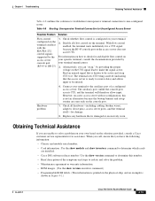
... determine which cards are installed. • Cisco IOS software release number: Use the show version executive command.) • Programmable ROM labels. (This information is printed on the physical chip, and an example is configured on the terminal conflicts with no configuration, this number. • Brief description of a configured access server. However, on a new access server with the EIA/TIA-232 control signals supported by your terminal manufacturer. 3. Hardware problem 1. Replace any hardware that is...
... determine which cards are installed. • Cisco IOS software release number: Use the show version executive command.) • Programmable ROM labels. (This information is printed on the physical chip, and an example is configured on the terminal conflicts with no configuration, this number. • Brief description of a configured access server. However, on a new access server with the EIA/TIA-232 control signals supported by your terminal manufacturer. 3. Hardware problem 1. Replace any hardware that is...
Installation Guide
Page 134
Index hardware problems booting routers 4-4 Cisco 7500 series routers 4-1, 4-2, 4-3 local timeouts, booting from ROM 4-22 routers booting from Flash memory 4-4, 4-5, 4-7, 4-8, 4-9, 4-11, 4-12, 4-14, 4-15, 4-17, 4-18, 4-19 hangs after ROM monitors initialize 4-20 stuck in ROM monitor mode 4-20, 4-21 scrambled output, booting from ROM 4-21 unresponsive terminal connections, unconfigured access servers 4-22, 4-23 hot swapping Cisco 7600 Internet Router components 1-4 supervisor engine and modules 1-39 I IEEE, recommended signaling requirements 2-10...
Index hardware problems booting routers 4-4 Cisco 7500 series routers 4-1, 4-2, 4-3 local timeouts, booting from ROM 4-22 routers booting from Flash memory 4-4, 4-5, 4-7, 4-8, 4-9, 4-11, 4-12, 4-14, 4-15, 4-17, 4-18, 4-19 hangs after ROM monitors initialize 4-20 stuck in ROM monitor mode 4-20, 4-21 scrambled output, booting from ROM 4-21 unresponsive terminal connections, unconfigured access servers 4-22, 4-23 hot swapping Cisco 7600 Internet Router components 1-4 supervisor engine and modules 1-39 I IEEE, recommended signaling requirements 2-10...


