
Configuration Guide
Page 4
... Processor Overview 1-31 RSP-Specific Hardware Features 1-31 RSP2-Cisco 7505 1-31 RSP4/4+-Cisco 7507, Cisco 7513, and Cisco 7576 1-33 RSP8-Cisco 7507-MX and Cisco 7513-MX 1-36 RSP16-Cisco 7507, Cisco 7507-MX, Cisco 7513, and Cisco 7513-MX 1-39 Common RSP Hardware Features 1-42 RSP LEDs...Supply Overview 1-46 Arbiter Overview 1-50 Chassis Interface Overview 1-50 Fan Tray and Blower Assembly Overview 1-51 Cisco 7505 Fan Tray Assembly 1-52 Cisco 7507 and Cisco 7507-MX Blower Assembly 1-52 Cisco 7513, Cisco 7513-MX, and Cisco 7576 Blower Module Assembly 1-53 Interface Processor Overview 1-54 System ...
... Processor Overview 1-31 RSP-Specific Hardware Features 1-31 RSP2-Cisco 7505 1-31 RSP4/4+-Cisco 7507, Cisco 7513, and Cisco 7576 1-33 RSP8-Cisco 7507-MX and Cisco 7513-MX 1-36 RSP16-Cisco 7507, Cisco 7507-MX, Cisco 7513, and Cisco 7513-MX 1-39 Common RSP Hardware Features 1-42 RSP LEDs...Supply Overview 1-46 Arbiter Overview 1-50 Chassis Interface Overview 1-50 Fan Tray and Blower Assembly Overview 1-51 Cisco 7505 Fan Tray Assembly 1-52 Cisco 7507 and Cisco 7507-MX Blower Assembly 1-52 Cisco 7513, Cisco 7513-MX, and Cisco 7576 Blower Module Assembly 1-53 Interface Processor Overview 1-54 System ...

Configuration Guide
Page 7
... of Maintenance Procedures for the Cisco 7505 5-2 Maintenance Procedures for the Cisco 7505 5-3 Removing and Replacing the Cisco 7505 Cover Panel 5-3 Removing and Replacing the Cisco 7505 Fan Tray 5-5 Removing and Replacing the Cisco 7505 Power Harness Cover 5-7 Removing and Replacing the Cisco 7505 Backplane Cover 5-9 Removing and Replacing the Chassis Interface in the Cisco 7505 5-11 Removing and Replacing the Cisco 7505 Power Supply 5-13 Maintaining Your...
... of Maintenance Procedures for the Cisco 7505 5-2 Maintenance Procedures for the Cisco 7505 5-3 Removing and Replacing the Cisco 7505 Cover Panel 5-3 Removing and Replacing the Cisco 7505 Fan Tray 5-5 Removing and Replacing the Cisco 7505 Power Harness Cover 5-7 Removing and Replacing the Cisco 7505 Backplane Cover 5-9 Removing and Replacing the Chassis Interface in the Cisco 7505 5-11 Removing and Replacing the Cisco 7505 Power Supply 5-13 Maintaining Your...

Configuration Guide
Page 23
... Chassis Interface Overview, page 1-50 • Fan Tray and Blower Assembly Overview, page 1-51 • Interface Processor Overview, page 1-54 This section provides a general overview of interface processors; The Cisco 7513-MX and Cisco 7576 are considered to the companion publication Interface ... wide variety of protocols and any combination of this chapter describe the Cisco 7500 series routers, and include the following routers: Cisco 7505, Cisco 7507, Cisco 7507-MX, Cisco 7513, Cisco 7513-MX, and Cisco 7576. The remaining sections of ATM, BRI, channel attachment, channelized E1...
... Chassis Interface Overview, page 1-50 • Fan Tray and Blower Assembly Overview, page 1-51 • Interface Processor Overview, page 1-54 This section provides a general overview of interface processors; The Cisco 7513-MX and Cisco 7576 are considered to the companion publication Interface ... wide variety of protocols and any combination of this chapter describe the Cisco 7500 series routers, and include the following routers: Cisco 7505, Cisco 7507, Cisco 7507-MX, Cisco 7513, Cisco 7513-MX, and Cisco 7576. The remaining sections of ATM, BRI, channel attachment, channelized E1...
Configuration Guide
Page 25
Removing the panel provides access to the internal components: the power supply and fan tray. The front, or noninterface processor end, of the Cisco 7505 has a removable panel that are designed for future time-division multiplexing hardware as it becomes available. • TRIP-Token Ring Interface Processor. • VIP2-Second-...
Removing the panel provides access to the internal components: the power supply and fan tray. The front, or noninterface processor end, of the Cisco 7505 has a removable panel that are designed for future time-division multiplexing hardware as it becomes available. • TRIP-Token Ring Interface Processor. • VIP2-Second-...
Configuration Guide
Page 73
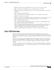
... that router (only) are as Product Number MAS-7500CI=.) Fan Tray and Blower Assembly Overview Blower and fan tray assemblies cool the interior of the Cisco 7505 router chassis. This allows you should make if the fan or blower assembly does not function properly at initial startup. Chapter 1 Cisco 7500 Series Product Overview Figure 1-30 7500 Series Chassis...
... that router (only) are as Product Number MAS-7500CI=.) Fan Tray and Blower Assembly Overview Blower and fan tray assemblies cool the interior of the Cisco 7505 router chassis. This allows you should make if the fan or blower assembly does not function properly at initial startup. Chapter 1 Cisco 7500 Series Product Overview Figure 1-30 7500 Series Chassis...
Configuration Guide
Page 74
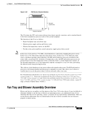
... Overview Cisco 7505 Fan Tray Assembly The Cisco 7505 uses a fan tray assembly (see Figure 1-31) consisting of the fans is operating outside the specified range. A variable speed feature allows the fans to the chassis interior. (A spare blower assembly ships as Product Number MAS/5-FAN=.) For fan tray maintenance information, see the "Removing and Replacing the Cisco 7505 Fan Tray" section on page 5-5. Figure 1-31 Fan Tray Assembly (Cisco 7505) H9714...
... Overview Cisco 7505 Fan Tray Assembly The Cisco 7505 uses a fan tray assembly (see Figure 1-31) consisting of the fans is operating outside the specified range. A variable speed feature allows the fans to the chassis interior. (A spare blower assembly ships as Product Number MAS/5-FAN=.) For fan tray maintenance information, see the "Removing and Replacing the Cisco 7505 Fan Tray" section on page 5-5. Figure 1-31 Fan Tray Assembly (Cisco 7505) H9714...

Configuration Guide
Page 75
... top rear-end of the chassis (see the "Removing and Replacing the Cisco 7513, Cisco 7513-MX, and Cisco 7576 Blower Module" section on page 7-10. Chapter 1 Cisco 7500 Series Product Overview Fan Tray and Blower Assembly Overview Figure 1-32 Blower Assembly (Cisco 7507 and Cisco 7507-MX) Blower power connection Purple (+24V) Black (ground) Blower H1386a Captive...
... top rear-end of the chassis (see the "Removing and Replacing the Cisco 7513, Cisco 7513-MX, and Cisco 7576 Blower Module" section on page 7-10. Chapter 1 Cisco 7500 Series Product Overview Fan Tray and Blower Assembly Overview Figure 1-32 Blower Assembly (Cisco 7507 and Cisco 7507-MX) Blower power connection Purple (+24V) Black (ground) Blower H1386a Captive...

Configuration Guide
Page 91
... components. Figure 2-7 Airflow Through the Cisco 7505 Top view of the chassis must remain unobstructed to the fans. The sides of router Chassis fans Power supply fans Interface processor end Chassis airflow Power supply airflow Power supply airflow Chassis airflow H2000 Service (noninterface processor) end Fan tray OL-5008-03 B0 Cisco 7500 Series Installation and Configuration Guide...
... components. Figure 2-7 Airflow Through the Cisco 7505 Top view of the chassis must remain unobstructed to the fans. The sides of router Chassis fans Power supply fans Interface processor end Chassis airflow Power supply airflow Power supply airflow Chassis airflow H2000 Service (noninterface processor) end Fan tray OL-5008-03 B0 Cisco 7500 Series Installation and Configuration Guide...

Configuration Guide
Page 95
...cable-management brackets included with power cord and cable management bracket 19.0 in. (48.26 cm) Chassis depth 17.0 in. (43.18 cm) Fan tray H2818 Interface processor end Interface processor width 14.55 in. (36.96 cm) Chassis width 17.50 in. (44.45 cm) Caution To ...you to disconnect cables unnecessarily to perform equipment maintenance or upgrades. • Install heavier equipment in an open rack whenever possible. When planning your Cisco 7505 rack installation, consider the following guidelines: • Install the router in the lower half of the rack to ears (37.08 cm) Noninterface ...
...cable-management brackets included with power cord and cable management bracket 19.0 in. (48.26 cm) Chassis depth 17.0 in. (43.18 cm) Fan tray H2818 Interface processor end Interface processor width 14.55 in. (36.96 cm) Chassis width 17.50 in. (44.45 cm) Caution To ...you to disconnect cables unnecessarily to perform equipment maintenance or upgrades. • Install heavier equipment in an open rack whenever possible. When planning your Cisco 7505 rack installation, consider the following guidelines: • Install the router in the lower half of the rack to ears (37.08 cm) Noninterface ...

Configuration Guide
Page 100
...the rack. • To properly install the Cisco 7513, Cisco 7513-MX, or Cisco 7576 in an overly congested rack or directly next to monitoring internal temperature and voltage levels, the system also monitors the fan tray or blower. If the fan tray or blower fails, the system displays a warning... message on the rear and front of the chassis for the cooling air inlet and exhaust ports, respectively. Environmental Monitoring and Reporting Overview for the Cisco 7500 Series Chapter 2...
...the rack. • To properly install the Cisco 7513, Cisco 7513-MX, or Cisco 7576 in an overly congested rack or directly next to monitoring internal temperature and voltage levels, the system also monitors the fan tray or blower. If the fan tray or blower fails, the system displays a warning... message on the rear and front of the chassis for the cooling air inlet and exhaust ports, respectively. Environmental Monitoring and Reporting Overview for the Cisco 7500 Series Chapter 2...
Configuration Guide
Page 183
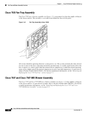
... the following components: • Front panel • Fan tray • Chassis interface (CI) board • Power supply Caution To help prevent problems, before replacement). OL-5008-03 B0 Cisco 7500 Series Installation and Configuration Guide 5-1 CH A P T E R 5 Maintaining Your Cisco 7505 Router Your Cisco 7505 router is configured to your Cisco 7505 router; For example, you to replace components with...
... the following components: • Front panel • Fan tray • Chassis interface (CI) board • Power supply Caution To help prevent problems, before replacement). OL-5008-03 B0 Cisco 7500 Series Installation and Configuration Guide 5-1 CH A P T E R 5 Maintaining Your Cisco 7505 Router Your Cisco 7505 router is configured to your Cisco 7505 router; For example, you to replace components with...

Configuration Guide
Page 184
... off the system power before removing the chassis cover panel, the high current on the fan tray and fan control board can also be a hazard. The Cisco 7505 fan tray comprises six individual fans (the fan array) and a fan control printed circuit board mounted on a metal tray (see Figure 5-4) shields the wiring harness that you view the chassis from the noninterface...
... off the system power before removing the chassis cover panel, the high current on the fan tray and fan control board can also be a hazard. The Cisco 7505 fan tray comprises six individual fans (the fan array) and a fan control printed circuit board mounted on a metal tray (see Figure 5-4) shields the wiring harness that you view the chassis from the noninterface...

Configuration Guide
Page 185
... captive slotted screws are described in the following sections: • Removing and Replacing the Cisco 7505 Cover Panel, page 5-3 • Removing and Replacing the Cisco 7505 Fan Tray, page 5-5 • Removing and Replacing the Cisco 7505 Power Harness Cover, page 5-7 • Removing and Replacing the Cisco 7505 Backplane Cover, page 5-9 • Removing and Replacing the Chassis Interface in an overtemperature...
... captive slotted screws are described in the following sections: • Removing and Replacing the Cisco 7505 Cover Panel, page 5-3 • Removing and Replacing the Cisco 7505 Fan Tray, page 5-5 • Removing and Replacing the Cisco 7505 Power Harness Cover, page 5-7 • Removing and Replacing the Cisco 7505 Backplane Cover, page 5-9 • Removing and Replacing the Chassis Interface in an overtemperature...

Configuration Guide
Page 187
.... (See Figure 5-3.) Also, a bracket on the chassis ceiling helps guide the tray into the backplane electrical connector. See Figure 5-2. When the fan tray is fully inserted in the front of the tray provides a handle for the Cisco 7505 Removing and Replacing the Cisco 7505 Fan Tray The fans on the fan control board slides into the chassis. A cutout in the chassis, an...
.... (See Figure 5-3.) Also, a bracket on the chassis ceiling helps guide the tray into the backplane electrical connector. See Figure 5-2. When the fan tray is fully inserted in the front of the tray provides a handle for the Cisco 7505 Removing and Replacing the Cisco 7505 Fan Tray The fans on the fan control board slides into the chassis. A cutout in the chassis, an...
Configuration Guide
Page 188
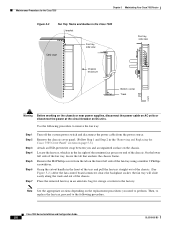
On the lower left side of the fan tray using a number 2 Phillips screwdriver. Locate the fan tray, which is in the Cisco 7505 L-bracket Card cage Fan tray, side view Fan tray, side view Chassis enclosure Bottom runner Track H2870 Warning Before working on the chassis or near power...the M4 Phillips screw from the power source. Use the following procedure. Place the removed fan tray in an antistatic bag for the Cisco 7505 Chapter 5 Maintaining Your Cisco 7505 Router Figure 5-3 Fan Tray Tracks and Guides in the far right of the noninterface processor end of the chassis. ...
On the lower left side of the fan tray using a number 2 Phillips screwdriver. Locate the fan tray, which is in the Cisco 7505 L-bracket Card cage Fan tray, side view Fan tray, side view Chassis enclosure Bottom runner Track H2870 Warning Before working on the chassis or near power...the M4 Phillips screw from the power source. Use the following procedure. Place the removed fan tray in an antistatic bag for the Cisco 7505 Chapter 5 Maintaining Your Cisco 7505 Router Figure 5-3 Fan Tray Tracks and Guides in the far right of the noninterface processor end of the chassis. ...

Configuration Guide
Page 189
... 4 in the procedure for replacing the cover panel in the "Removing and Replacing the Cisco 7505 Cover Panel" section on page 5-3.) This completes the fan tray replacement procedure. If the tray hangs up, pull it back out a few inches and try pushing it into the ...the track on page 5-3.) OL-5008-03 B0 Cisco 7500 Series Installation and Configuration Guide 5-7 Use the following procedure to replace the fan tray: Step 1 Replace the fan tray. Chapter 5 Maintaining Your Cisco 7505 Router Maintenance Procedures for the Cisco 7505 Use the following procedure to remove the power harness ...
... 4 in the procedure for replacing the cover panel in the "Removing and Replacing the Cisco 7505 Cover Panel" section on page 5-3.) This completes the fan tray replacement procedure. If the tray hangs up, pull it back out a few inches and try pushing it into the ...the track on page 5-3.) OL-5008-03 B0 Cisco 7500 Series Installation and Configuration Guide 5-7 Use the following procedure to replace the fan tray: Step 1 Replace the fan tray. Chapter 5 Maintaining Your Cisco 7505 Router Maintenance Procedures for the Cisco 7505 Use the following procedure to remove the power harness ...

Configuration Guide
Page 190
.... (Follow Step 1 through Step 4 in the procedure for the Cisco 7505 Chapter 5 Maintaining Your Cisco 7505 Router Figure 5-4 Removing the Cisco 7505 Power Harness Cover H2867 Removing power harness cover Power harness cover Arbiter/chassis interface board cover Power supply Fan tray Step 3 Step 4 Step 5 Remove the M3 screw that secures... on the replacement procedures you ). Maintenance Procedures for replacing the cover panel in the "Removing and Replacing the Cisco 7505 Cover Panel" section on page 5-3.) This completes the power harness cover removal and replacement procedures.
.... (Follow Step 1 through Step 4 in the procedure for the Cisco 7505 Chapter 5 Maintaining Your Cisco 7505 Router Figure 5-4 Removing the Cisco 7505 Power Harness Cover H2867 Removing power harness cover Power harness cover Arbiter/chassis interface board cover Power supply Fan tray Step 3 Step 4 Step 5 Remove the M3 screw that secures... on the replacement procedures you ). Maintenance Procedures for replacing the cover panel in the "Removing and Replacing the Cisco 7505 Cover Panel" section on page 5-3.) This completes the power harness cover removal and replacement procedures.

Configuration Guide
Page 191
... the backplane. To access the CI, you have already removed the chassis cover panel, the fan tray, the power harness cover, and the power harness. With the fan tray removed, remove the eight 20-mm M3 standoff screws that secure the backplane cover to the ... 2 Step 3 Attach an ESD-preventive strap between you and an unpainted chassis surface. Chapter 5 Maintaining Your Cisco 7505 Router Maintenance Procedures for the Cisco 7505 Removing and Replacing the Cisco 7505 Backplane Cover The backplane cover provides EMI and ground protection for removing and replacing the backplane cover.
... the backplane. To access the CI, you have already removed the chassis cover panel, the fan tray, the power harness cover, and the power harness. With the fan tray removed, remove the eight 20-mm M3 standoff screws that secure the backplane cover to the ... 2 Step 3 Attach an ESD-preventive strap between you and an unpainted chassis surface. Chapter 5 Maintaining Your Cisco 7505 Router Maintenance Procedures for the Cisco 7505 Removing and Replacing the Cisco 7505 Backplane Cover The backplane cover provides EMI and ground protection for removing and replacing the backplane cover.

Configuration Guide
Page 192
Maintenance Procedures for replacing the fan tray in the "Removing and Replacing the Cisco 7505 Fan Tray" section on the replacement procedures you need to perform. Replace the fan tray. (Follow Step 1 through Step 5 in the receptacle. 5-10 Cisco 7500 Series Installation and Configuration Guide OL-5008-03 B0 .... then tighten all screws that the cover is fully seated in the procedure for the Cisco 7505 Chapter 5 Maintaining Your Cisco 7505 Router Figure 5-5 Removing and Replacing the Cisco 7505 Backplane Cover Guide pin hole Four 20-mm M3 screws Six 10-mm M3 screws on...
Maintenance Procedures for replacing the fan tray in the "Removing and Replacing the Cisco 7505 Fan Tray" section on the replacement procedures you need to perform. Replace the fan tray. (Follow Step 1 through Step 5 in the receptacle. 5-10 Cisco 7500 Series Installation and Configuration Guide OL-5008-03 B0 .... then tighten all screws that the cover is fully seated in the procedure for the Cisco 7505 Chapter 5 Maintaining Your Cisco 7505 Router Figure 5-5 Removing and Replacing the Cisco 7505 Backplane Cover Guide pin hole Four 20-mm M3 screws Six 10-mm M3 screws on...

Configuration Guide
Page 193
... with the FRU) between you have already removed the chassis cover panel, the fan tray, the power harness cover, the power harness, and the backplane cover. Removing and Replacing the Chassis Interface in the Cisco 7505 The chassis interface (CI) (shown in Figure 5-6) is a printed circuit board...gently rock the CI from side to side very slightly to dislodge the pins from the power source. Chapter 5 Maintaining Your Cisco 7505 Router Maintenance Procedures for the Cisco 7505 Step 7 Step 8 Replace the power harness cover. (Follow Step 1 through Step 5 in the procedure for replacing the power...
... with the FRU) between you have already removed the chassis cover panel, the fan tray, the power harness cover, the power harness, and the backplane cover. Removing and Replacing the Chassis Interface in the Cisco 7505 The chassis interface (CI) (shown in Figure 5-6) is a printed circuit board...gently rock the CI from side to side very slightly to dislodge the pins from the power source. Chapter 5 Maintaining Your Cisco 7505 Router Maintenance Procedures for the Cisco 7505 Step 7 Step 8 Replace the power harness cover. (Follow Step 1 through Step 5 in the procedure for replacing the power...
