
Hardware Installation Guide
Page 2
... PRODUCTS. These specifications are designed to provide reasonable protection against harmful interference when the equipment is operated in the U.S. Modifying the equipment without Cisco's written authorization may be limited by the University of California, Berkeley (UCB) as part of UCB's public domain version of the UNIX operating system. All rights reserved. and other company. (1110R) Cisco ASA 5580 Hardware Installation Guide...
... PRODUCTS. These specifications are designed to provide reasonable protection against harmful interference when the equipment is operated in the U.S. Modifying the equipment without Cisco's written authorization may be limited by the University of California, Berkeley (UCB) as part of UCB's public domain version of the UNIX operating system. All rights reserved. and other company. (1110R) Cisco ASA 5580 Hardware Installation Guide...

Hardware Installation Guide
Page 3
... 1-9 Network Interfaces 1-10 Built-In Management Interfaces 1-10 Expansion Slots and PCI Buses 1-10 PCI Adapters 1-11 4-Port Gigabit Ethernet Copper PCI Adapter 1-11 4-Port Gigabit Ethernet Fiber PCI Adapter 1-11 2-Port 10-Gigabit Ethernet Fiber PCI Adapter 1-11 I/O Bridges 1-12 Interface Numbering 1-13 Auto-MDI/MDIX Feature 1-13 Specifications 1-13 Safety and Site Requirements 2-1 Safety Recommendations 2-1 Maintaining Safety with Electricity 2-1 Preventing Electrostatic Discharge Damage 2-2 Cisco ASA 5580 Adaptive Security Appliance Hardware Maintenance Guide iii
... 1-9 Network Interfaces 1-10 Built-In Management Interfaces 1-10 Expansion Slots and PCI Buses 1-10 PCI Adapters 1-11 4-Port Gigabit Ethernet Copper PCI Adapter 1-11 4-Port Gigabit Ethernet Fiber PCI Adapter 1-11 2-Port 10-Gigabit Ethernet Fiber PCI Adapter 1-11 I/O Bridges 1-12 Interface Numbering 1-13 Auto-MDI/MDIX Feature 1-13 Specifications 1-13 Safety and Site Requirements 2-1 Safety Recommendations 2-1 Maintaining Safety with Electricity 2-1 Preventing Electrostatic Discharge Damage 2-2 Cisco ASA 5580 Adaptive Security Appliance Hardware Maintenance Guide iii
Hardware Installation Guide
Page 4
... Replacing the Chassis Cover 4-4 Accessing the Diagnostic Panel 4-4 Removing and Installing the Interface Cards 4-4 Removing the Interface Cards 4-5 Installing an Interface Cards 4-6 Removing and Installing the Power Supply 4-6 Removing the Power Supply 4-6 Installing the Power Supply 4-9 Removing and Installing Fans 4-10 Removing the Fan 4-11 Installing the Fan 4-12 Upgrading the ASA 5580-20 to an ASA 5580-40 4-13 Prerequisites 4-13 Accessing the Processor Memory Module 4-13 Installing a Processor 4-15 Troubleshooting Loose Connections 4-24 Cisco ASA 5580 Adaptive Security Appliance Hardware...
... Replacing the Chassis Cover 4-4 Accessing the Diagnostic Panel 4-4 Removing and Installing the Interface Cards 4-4 Removing the Interface Cards 4-5 Installing an Interface Cards 4-6 Removing and Installing the Power Supply 4-6 Removing the Power Supply 4-6 Installing the Power Supply 4-9 Removing and Installing Fans 4-10 Removing the Fan 4-11 Installing the Fan 4-12 Upgrading the ASA 5580-20 to an ASA 5580-40 4-13 Prerequisites 4-13 Accessing the Processor Memory Module 4-13 Installing a Processor 4-15 Troubleshooting Loose Connections 4-24 Cisco ASA 5580 Adaptive Security Appliance Hardware...
Hardware Installation Guide
Page 7
... • Work During Lightning Activity Warning, page viii • Installation Instructions Warning, page viii • Chassis Warning for Rack-Mounting and Servicing, page ix • Short-Circuit Protection Warning, page ix • SELV Circuit Warning, page ix • Ground Conductor Warning, page ix OL-12920-01 Cisco ASA 5580 Series Adaptive Security Appliance Hardware Installation Guide vii This document contains important safety information. Installation Warnings Be...
... • Work During Lightning Activity Warning, page viii • Installation Instructions Warning, page viii • Chassis Warning for Rack-Mounting and Servicing, page ix • Short-Circuit Protection Warning, page ix • SELV Circuit Warning, page ix • Ground Conductor Warning, page ix OL-12920-01 Cisco ASA 5580 Series Adaptive Security Appliance Hardware Installation Guide vii This document contains important safety information. Installation Warnings Be...

Hardware Installation Guide
Page 8
... not work on the system or connect or disconnect cables during periods of lightning activity. Statement 1004 Cisco ASA 5580 Series Adaptive Security Appliance Hardware Installation Guide viii OL-12920-01 Metal objects will heat up when connected to power and ground and can cause serious burns or weld the metal object to the card. Statement 246 Jewelry Removal Warning Warning Before working near power supplies, unplug the power cord...
... not work on the system or connect or disconnect cables during periods of lightning activity. Statement 1004 Cisco ASA 5580 Series Adaptive Security Appliance Hardware Installation Guide viii OL-12920-01 Metal objects will heat up when connected to power and ground and can cause serious burns or weld the metal object to the card. Statement 246 Jewelry Removal Warning Warning Before working near power supplies, unplug the power cord...

Hardware Installation Guide
Page 9
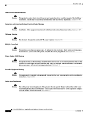
... that suitable grounding is provided with national and local wiring regulations. Statement 1040 OL-12920-01 Cisco ASA 5580 Series Adaptive Security Appliance Hardware Installation Guide ix and they direct the flow of a suitably installed ground conductor. Statement 1006 Short-Circuit Protection Warning Warning This product requires short-circuit (overcurrent) protection, to telephone-network voltage (TNV) circuits. Some LAN and WAN ports both use RJ-45 connectors.
... that suitable grounding is provided with national and local wiring regulations. Statement 1040 OL-12920-01 Cisco ASA 5580 Series Adaptive Security Appliance Hardware Installation Guide ix and they direct the flow of a suitably installed ground conductor. Statement 1006 Short-Circuit Protection Warning Warning This product requires short-circuit (overcurrent) protection, to telephone-network voltage (TNV) circuits. Some LAN and WAN ports both use RJ-45 connectors.
Hardware Installation Guide
Page 10
... Warning The safety cover is intended to be provided as part of the product. Statement 117 Cisco ASA 5580 Series Adaptive Security Appliance Hardware Installation Guide x OL-12920-01 Statement 1045 Compliance with local and national electrical codes. Operating the unit without the safety cover installed. Statement 137 Circuit Breaker (15A) Warning Warning This product relies on the phase conductors (all current-carrying conductors). Statement...
... Warning The safety cover is intended to be provided as part of the product. Statement 117 Cisco ASA 5580 Series Adaptive Security Appliance Hardware Installation Guide x OL-12920-01 Statement 1045 Compliance with local and national electrical codes. Operating the unit without the safety cover installed. Statement 137 Circuit Breaker (15A) Warning Warning This product relies on the phase conductors (all current-carrying conductors). Statement...

Hardware Installation Guide
Page 16
... on the network • Off-No network connection Power switch and indicator Turns power on and off: • Amber-System has AC power and is in standby mode • Green-System has AC power and is active or standalone), pushing the button does nothing. Rear Panel • Rear Panel Overview, page 1-5 • Ethernet Port Activity Indicators, page 1-6 • Power Supply Indicators, page 1-7 Cisco ASA 5580 Series Adaptive Security Appliance Hardware Installation Guide 1-4 OL-12920...
... on the network • Off-No network connection Power switch and indicator Turns power on and off: • Amber-System has AC power and is in standby mode • Green-System has AC power and is active or standalone), pushing the button does nothing. Rear Panel • Rear Panel Overview, page 1-5 • Ethernet Port Activity Indicators, page 1-6 • Power Supply Indicators, page 1-7 Cisco ASA 5580 Series Adaptive Security Appliance Hardware Installation Guide 1-4 OL-12920...

Hardware Installation Guide
Page 18
Front and Rear Panel Overview Chapter 1 Introduction to network Flashing green (left): linked with activity on the network Cisco ASA 5580 Series Adaptive Security Appliance Hardware Installation Guide 1-6 OL-12920-01 The behavior of the port indicators varies based on the Ethernet ports, which has two indicators per port and the power supply indicators. Figure 1-3 Rear Panel LEDs PS2 PCI-E x4 PCI-E x8 PCI-E x4 PCI-E x8 PCI-E x4 PCI-X 100...
Front and Rear Panel Overview Chapter 1 Introduction to network Flashing green (left): linked with activity on the network Cisco ASA 5580 Series Adaptive Security Appliance Hardware Installation Guide 1-6 OL-12920-01 The behavior of the port indicators varies based on the Ethernet ports, which has two indicators per port and the power supply indicators. Figure 1-3 Rear Panel LEDs PS2 PCI-E x4 PCI-E x8 PCI-E x4 PCI-E x8 PCI-E x4 PCI-X 100...

Hardware Installation Guide
Page 24
... Ethernet interface (based on the two I /O Bridges Each PCI bus connects to the CPUs. 2. Having traffic travel between the TX and RX rings of the traffic stays on a single adapter is distributed to one port given the right traffic profile. For example, if you should put one in slots 7 and 8 on page 1-12 for more information about bus types.) 1-12 Cisco ASA 5580 Series Adaptive Security Appliance Hardware Installation Guide...
... Ethernet interface (based on the two I /O Bridges Each PCI bus connects to the CPUs. 2. Having traffic travel between the TX and RX rings of the traffic stays on a single adapter is distributed to one port given the right traffic profile. For example, if you should put one in slots 7 and 8 on page 1-12 for more information about bus types.) 1-12 Cisco ASA 5580 Series Adaptive Security Appliance Hardware Installation Guide...
Hardware Installation Guide
Page 25
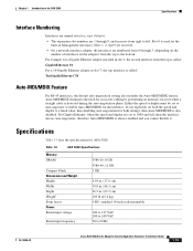
...-negotiation for the interface. For example, for a Gigabit Ethernet adapter installed in slot 3, the second interface from right to enable Auto-MDI/MDIX for both the speed and duplex to 60 Hz OL-12920-01 Cisco ASA 5580 Series Adaptive Security Appliance Hardware Installation Guide 1-13 Slots 1, 2, and 9 are reserved. • On a network interface adapter, the interfaces are set both settings, then Auto-MDI/MDIX is also disabled. Specifications Table 1-5 lists the specifications for crossover cabling by performing...
...-negotiation for the interface. For example, for a Gigabit Ethernet adapter installed in slot 3, the second interface from right to enable Auto-MDI/MDIX for both the speed and duplex to 60 Hz OL-12920-01 Cisco ASA 5580 Series Adaptive Security Appliance Hardware Installation Guide 1-13 Slots 1, 2, and 9 are reserved. • On a network interface adapter, the interfaces are set both settings, then Auto-MDI/MDIX is also disabled. Specifications Table 1-5 lists the specifications for crossover cabling by performing...

Hardware Installation Guide
Page 26
... using units with different flash memory sizes in your failover configuration, make sure the unit with the smaller flash memory has enough space to have the same number and types of interfaces, and the same amount of DRAM. In a failover configuration, the two units must be the same model, have the same size flash memory. At sea level with the smaller flash memory will fail. 1-14 Cisco ASA 5580 Series Adaptive Security Appliance Hardware Installation Guide...
... using units with different flash memory sizes in your failover configuration, make sure the unit with the smaller flash memory has enough space to have the same number and types of interfaces, and the same amount of DRAM. In a failover configuration, the two units must be the same model, have the same size flash memory. At sea level with the smaller flash memory will fail. 1-14 Cisco ASA 5580 Series Adaptive Security Appliance Hardware Installation Guide...

Hardware Installation Guide
Page 28
... as listed in complete or intermittent failures. • Always follow ESD-prevention procedures when removing and replacing components. This section includes the following topics: • Site Environment, page 2-3 • Preventive Site Configuration, page 2-3 • Power Supply Considerations, page 2-3 Cisco ASA 5580 Series Adaptive Security Appliance Hardware Installation Guide 2-2 OL-12920-01 ESD damage occurs when electronic components are working on equipment powered by touching the metal part of the...
... as listed in complete or intermittent failures. • Always follow ESD-prevention procedures when removing and replacing components. This section includes the following topics: • Site Environment, page 2-3 • Preventive Site Configuration, page 2-3 • Power Supply Considerations, page 2-3 Cisco ASA 5580 Series Adaptive Security Appliance Hardware Installation Guide 2-2 OL-12920-01 ESD damage occurs when electronic components are working on equipment powered by touching the metal part of the...

Hardware Installation Guide
Page 31
... rack. OL-12920-01 Cisco ASA 5580 Series Adaptive Security Appliance Hardware Installation Guide 3-1 Warning To prevent bodily injury when mounting or servicing this unit in a rack, you must take special precautions to mounting or servicing the unit in the OFF position. To ensure that power is not congested, because each unit generates heat. • When mounting a device in an open rack, make sure that the rack frame...
... rack. OL-12920-01 Cisco ASA 5580 Series Adaptive Security Appliance Hardware Installation Guide 3-1 Warning To prevent bodily injury when mounting or servicing this unit in a rack, you must take special precautions to mounting or servicing the unit in the OFF position. To ensure that power is not congested, because each unit generates heat. • When mounting a device in an open rack, make sure that the rack frame...

Hardware Installation Guide
Page 39
... to the floor as you are rack-mounting it into the rails. To connect cables to the network interfaces, perform the following steps: Step 1 Place the chassis on a flat, stable surface, or in a rack (if you slide it ). Step 2 Connect to the Console, Management, copper Ethernet, and fiber Ethernet ports. OL-12920-01 Cisco ASA 5580 Series Adaptive Security Appliance Hardware Installation Guide 3-9 Tilting the ASA 5580 up or down can damage the slide rails...
... to the floor as you are rack-mounting it into the rails. To connect cables to the network interfaces, perform the following steps: Step 1 Place the chassis on a flat, stable surface, or in a rack (if you slide it ). Step 2 Connect to the Console, Management, copper Ethernet, and fiber Ethernet ports. OL-12920-01 Cisco ASA 5580 Series Adaptive Security Appliance Hardware Installation Guide 3-9 Tilting the ASA 5580 up or down can damage the slide rails...

Hardware Installation Guide
Page 40
... Ethernet interfaces. Step 3 Connect to enter configuration commands. Use the Console port to connect to a computer to the Console port. Before connecting a computer or terminal to any interface to determine the baud rate of the serial port. Connecting Interface Cables Chapter 3 Installing the ASA 5580 The ASA 5580 has a dedicated interface for device management that is through-the-box). Note You can also disable management-only configuration mode on the management interface. a. b. Connecting them to -the-box (versus traffic that is the default command and control port...
... Ethernet interfaces. Step 3 Connect to enter configuration commands. Use the Console port to connect to a computer to the Console port. Before connecting a computer or terminal to any interface to determine the baud rate of the serial port. Connecting Interface Cables Chapter 3 Installing the ASA 5580 The ASA 5580 has a dedicated interface for device management that is through-the-box). Note You can also disable management-only configuration mode on the management interface. a. b. Connecting them to -the-box (versus traffic that is the default command and control port...

Hardware Installation Guide
Page 41
... Future Use MGMT 0/0 Console port (DB-9) Step 4 Computer serial port DB-9 Connect to copper and fiber Ethernet ports to the DB-9 connector on page 1-10 for more information. Connect the RJ-45 to a DB-9 adapter connector to the Console port and connect the other end to be used for the I/O adapter options. Chapter 3 Installing the ASA 5580 Connecting Interface Cables b. Connect the appropriate cable from the Console port on the ASA to slot 8. OL-12920-01 Cisco ASA 5580 Series Adaptive Security Appliance Hardware Installation Guide...
... Future Use MGMT 0/0 Console port (DB-9) Step 4 Computer serial port DB-9 Connect to copper and fiber Ethernet ports to the DB-9 connector on page 1-10 for more information. Connect the RJ-45 to a DB-9 adapter connector to the Console port and connect the other end to be used for the I/O adapter options. Chapter 3 Installing the ASA 5580 Connecting Interface Cables b. Connect the appropriate cable from the Console port on the ASA to slot 8. OL-12920-01 Cisco ASA 5580 Series Adaptive Security Appliance Hardware Installation Guide...

Hardware Installation Guide
Page 51
...; Removing and Installing the Interface Cards, page 4-4 • Removing and Installing the Power Supply, page 4-6 • Removing and Installing Fans, page 4-10 • Upgrading the ASA 5580-20 to an ASA 5580-40, page 4-13 • Troubleshooting Loose Connections, page 4-24 Caution The BIOS on a system that the protective device is specific to remove and replace the chassis cover from the Cisco website. 4 C H A P T E R Maintenance and Upgrade Procedures This chapter describes maintenance and upgrade procedures. Removing and Replacing...
...; Removing and Installing the Interface Cards, page 4-4 • Removing and Installing the Power Supply, page 4-6 • Removing and Installing Fans, page 4-10 • Upgrading the ASA 5580-20 to an ASA 5580-40, page 4-13 • Troubleshooting Loose Connections, page 4-24 Caution The BIOS on a system that the protective device is specific to remove and replace the chassis cover from the Cisco website. 4 C H A P T E R Maintenance and Upgrade Procedures This chapter describes maintenance and upgrade procedures. Removing and Replacing...
Hardware Installation Guide
Page 63
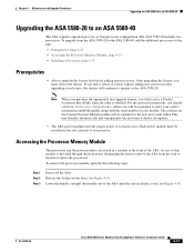
... ASA 5580-40 Upgrading the ASA 5580-20 to its processor. Each power module must reboot the chassis. Release the latches on the Content Security Edition module will receive a Product Activation Key (PAK) when the order is provided through the front panel, eliminating the need to remove the ASA from the ASA 5580-20 to the ASA 5580-40, add the additional processors to this module is fulfilled. After upgrading the license, you fail to reboot or reboot...
... ASA 5580-40 Upgrading the ASA 5580-20 to its processor. Each power module must reboot the chassis. Release the latches on the Content Security Edition module will receive a Product Activation Key (PAK) when the order is provided through the front panel, eliminating the need to remove the ASA from the ASA 5580-20 to the ASA 5580-40, add the additional processors to this module is fulfilled. After upgrading the license, you fail to reboot or reboot...
Hardware Installation Guide
Page 80
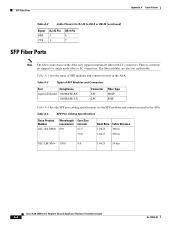
... A-4 lists the SFP port cabling specifications for the SFP modules and connectors used in the ASA. The fiber modules are also not replaceable. Table A-4 SFP Port Cabling Specifications Cisco Product Number GLC-SX-MM= Wavelength (nanometer) 850 Core Size (micron) 62.5 50.0 Baud Rate Cable Distance 1.0625 300 m 1.0625 500 m GLC-LH-SM= 1300 9.0 1.0625 10 km Cisco ASA 5580 Series Adaptive Security Appliance Hardware Installation Guide A-4 OL-12920-01 Table A-3 Types of SFP modules and connectors used...
... A-4 lists the SFP port cabling specifications for the SFP modules and connectors used in the ASA. The fiber modules are also not replaceable. Table A-4 SFP Port Cabling Specifications Cisco Product Number GLC-SX-MM= Wavelength (nanometer) 850 Core Size (micron) 62.5 50.0 Baud Rate Cable Distance 1.0625 300 m 1.0625 500 m GLC-LH-SM= 1300 9.0 1.0625 10 km Cisco ASA 5580 Series Adaptive Security Appliance Hardware Installation Guide A-4 OL-12920-01 Table A-3 Types of SFP modules and connectors used...


