Hardware Installation Guide
Page 18
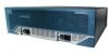
Cisco Access Routers and Cisco Network Modules Chapter 1 Overview of Cisco Network Modules for Cisco Access Routers Figure 1-5 Cisco 3660 Router Rear View VCC OK SYSTEM FDX LINK 100Mbps FDX LINK 1 100Mbps 0 121093 1 2 3 4 1 Network module slot 2 2 Network module slot 4 3 Network module slot 6 Figure 1-6 Chassis Slot Locations in Cisco 2851 Routers 42 31 S A= ACT A= FDX L O S L S= SPEED A= LINK T O A GE 0/1 GE 0/0 3 A T 2 F F S SS L S L LO L T O 1 T PVDM2 PVDM1 PVDM0...
Cisco Access Routers and Cisco Network Modules Chapter 1 Overview of Cisco Network Modules for Cisco Access Routers Figure 1-5 Cisco 3660 Router Rear View VCC OK SYSTEM FDX LINK 100Mbps FDX LINK 1 100Mbps 0 121093 1 2 3 4 1 Network module slot 2 2 Network module slot 4 3 Network module slot 6 Figure 1-6 Chassis Slot Locations in Cisco 2851 Routers 42 31 S A= ACT A= FDX L O S L S= SPEED A= LINK T O A GE 0/1 GE 0/0 3 A T 2 F F S SS L S L LO L T O 1 T PVDM2 PVDM1 PVDM0...
Hardware Installation Guide
Page 160
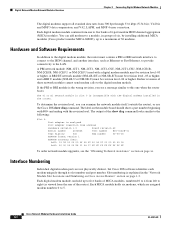
... modem numbers 0 to this one to the ISDN channel, and another interface, such as viewed from 300 bps through its slot number and port number. and V.42, LAPM, and ... 4 error correction. Each MICA module holds six modems, which are not physically distinct, but Cisco IOS software identifies each modem uniquely through 33.6 kbps (V.34 bis); and ending with the digital...Connecting Digital Modem Network Modules The digital modems support all standard data rates from the rear of the router). To determine the revision level, you see the "Obtaining Technical Assistance" section on...
... modem numbers 0 to this one to the ISDN channel, and another interface, such as viewed from 300 bps through its slot number and port number. and V.42, LAPM, and ... 4 error correction. Each MICA module holds six modems, which are not physically distinct, but Cisco IOS software identifies each modem uniquely through 33.6 kbps (V.34 bis); and ending with the digital...Connecting Digital Modem Network Modules The digital modems support all standard data rates from the rear of the router). To determine the revision level, you see the "Obtaining Technical Assistance" section on...
Hardware Installation Guide
Page 161
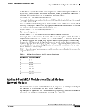
... example, the third modem (modem 2) in the second MICA module from the rear of interface numbers available in the router chassis. This is also the line and TTY number for the port. The...and alignment holes that fit over guide posts to a Digital Modem Network Module You can also be expressed as viewed from the left MICA module (as : interface-number = (32 x slot-number) + ((6 x bank-number...Adding 6-Port MICA Modules to ensure proper positioning. (See Figure 9-2.) OL-2485-20 Cisco Network Modules Hardware Installation Guide 9-3 If you move the MICA module to a different position...
... example, the third modem (modem 2) in the second MICA module from the rear of interface numbers available in the router chassis. This is also the line and TTY number for the port. The...and alignment holes that fit over guide posts to a Digital Modem Network Module You can also be expressed as viewed from the left MICA module (as : interface-number = (32 x slot-number) + ((6 x bank-number...Adding 6-Port MICA Modules to ensure proper positioning. (See Figure 9-2.) OL-2485-20 Cisco Network Modules Hardware Installation Guide 9-3 If you move the MICA module to a different position...

Hardware Guide
Page 16
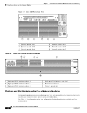
... Power System (RPS) connector 2 CompactFlash memory card slot 3 USB ports 4 LED indicators 5 Power switch 6 Power connector (AC shown) Figure 3 Rear View of Cisco 3825 Router NE36SMWD-- 35x GE1 1B0a/s1e0-0T/x1000 17x FastEthernet Ports NME16SW- 15x 7x 15x 7x 35x 17x 34x 16x 33x 15x 32x 14x FastEthernet Ports ...
... Power System (RPS) connector 2 CompactFlash memory card slot 3 USB ports 4 LED indicators 5 Power switch 6 Power connector (AC shown) Figure 3 Rear View of Cisco 3825 Router NE36SMWD-- 35x GE1 1B0a/s1e0-0T/x1000 17x FastEthernet Ports NME16SW- 15x 7x 15x 7x 35x 17x 34x 16x 33x 15x 32x 14x FastEthernet Ports ...
Hardware Guide
Page 17
Router Descriptions Figure 4 Rear Panel of Cisco 3825 Router 1 NMDESW36 35x GE1 FastEthernet Ports 18x 2 10/100/1000 Base-Tx 17x 35x 17x 34x 16x 33x 15x 32x 14x 31x 13x 30x 12x 29x ... 10/100/ 1000 Base-Tx EN 3 45 67 2 CONSOLE SPD GE 0/1 LNK H W I C 2 Cisco 3825 H W I C 0 AUX SPD GE 0/0 LNK SFP 8 9 10 1 Network module slot 2 2 Screw holes for grounding lug 3 Network module slot 1 4 HWIC slot 3 5 HWIC slot 1 Figure 5 Front View of Cisco 3845 Router 6 HWIC slot 2 7 HWIC slot 0 8 Console and auxiliary ports 9 Gigabit Ethernet ports 10 Slot...
Router Descriptions Figure 4 Rear Panel of Cisco 3825 Router 1 NMDESW36 35x GE1 FastEthernet Ports 18x 2 10/100/1000 Base-Tx 17x 35x 17x 34x 16x 33x 15x 32x 14x 31x 13x 30x 12x 29x ... 10/100/ 1000 Base-Tx EN 3 45 67 2 CONSOLE SPD GE 0/1 LNK H W I C 2 Cisco 3825 H W I C 0 AUX SPD GE 0/0 LNK SFP 8 9 10 1 Network module slot 2 2 Screw holes for grounding lug 3 Network module slot 1 4 HWIC slot 3 5 HWIC slot 1 Figure 5 Front View of Cisco 3845 Router 6 HWIC slot 2 7 HWIC slot 0 8 Console and auxiliary ports 9 Gigabit Ethernet ports 10 Slot...

Hardware Guide
Page 18
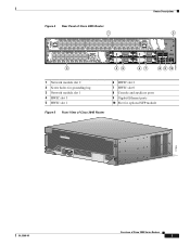
Router Descriptions Figure 6 Front Panel of Cisco 3845 Router 1 2 3 4 1 LED indicators 2 Power switch 3 Power connector (AC shown) 4 Location of optional second power supply Figure 7 Rear View of Cisco 3845 Router 116843 117774 Overview of Cisco 3800 Series Routers 4 OL-5966-01
Router Descriptions Figure 6 Front Panel of Cisco 3845 Router 1 2 3 4 1 LED indicators 2 Power switch 3 Power connector (AC shown) 4 Location of optional second power supply Figure 7 Rear View of Cisco 3845 Router 116843 117774 Overview of Cisco 3800 Series Routers 4 OL-5966-01

Hardware Guide
Page 86
... guide rails begin approximately 1 inch (3 cm) from the router's rear panel. Installing and Removing Slot Dividers Installing Slot Dividers Figure 33 shows a slot divider for Network Module Slot 121384 To install slot dividers in Cisco 3800 Series Routers 56 OL-5973-01 See Figure 34. Step 1 Insert the... top rails of the slot divider between the guide rails in the top of a Cisco 3800 series routers. It does not represent a detailed view of the network module slot. ...
... guide rails begin approximately 1 inch (3 cm) from the router's rear panel. Installing and Removing Slot Dividers Installing Slot Dividers Figure 33 shows a slot divider for Network Module Slot 121384 To install slot dividers in Cisco 3800 Series Routers 56 OL-5973-01 See Figure 34. Step 1 Insert the... top rails of the slot divider between the guide rails in the top of a Cisco 3800 series routers. It does not represent a detailed view of the network module slot. ...

Hardware Guide
Page 93
..., its outer end is flush with the router's rear panel. Push the slot divider in Cisco 3800 Series Routers 63 OL-5974-01 Installing Interface Cards in until it locks into HWIC slots, follow these steps: Step 1 For a Cisco 3825 router, squeeze the prongs of the metal slot ...divider together and insert the ends between the guide rails on the bottom of the HWIC slot. See Figure 39. Figure 38 Slot Divider for Cisco 3845 HWIC Slot 1 Installing and Removing Slot Dividers 2 121560 1 Rear view 2 Front view To install...
..., its outer end is flush with the router's rear panel. Push the slot divider in Cisco 3800 Series Routers 63 OL-5974-01 Installing Interface Cards in until it locks into HWIC slots, follow these steps: Step 1 For a Cisco 3825 router, squeeze the prongs of the metal slot ...divider together and insert the ends between the guide rails on the bottom of the HWIC slot. See Figure 39. Figure 38 Slot Divider for Cisco 3845 HWIC Slot 1 Installing and Removing Slot Dividers 2 121560 1 Rear view 2 Front view To install...

Hardware Guide
Page 97
...flow of cooling air through the chassis. Do not operate the system unless all cards, faceplates, front covers, and rear covers are in Cisco 3800 Series Routers 67 Figure 42 Blank Faceplate for Interface Card Slot DO NOT INSTALL WAN INTERFACE CARDS WITH POWER APPLIED 41205 Figure 43 ...Blank Faceplate for Interface Card Slot (Perspective View) 121066 OL-5974-01 Installing Interface Cards in place. Installing Blank Faceplates...
...flow of cooling air through the chassis. Do not operate the system unless all cards, faceplates, front covers, and rear covers are in Cisco 3800 Series Routers 67 Figure 42 Blank Faceplate for Interface Card Slot DO NOT INSTALL WAN INTERFACE CARDS WITH POWER APPLIED 41205 Figure 43 ...Blank Faceplate for Interface Card Slot (Perspective View) 121066 OL-5974-01 Installing Interface Cards in place. Installing Blank Faceplates...