
Quick Start Guide
Page 30
...(CLI)-See the "Initial Configuration Using the Cisco CLI-Manual Configuration" section on page 33. To configure the line associated with interface async 1/22 on an NM-32A in slot 3. See the Cisco Interface Cards Installation Guide for asynchronous interfaces as...the startup sequence, Cisco Router and Security Device Manager (SDM) is installed on your router: yourname con0 is 1, 2, 3, or 4. Interface Card Ports Interface cards can configure your router by using one of the following messages appear at 0. Note On the Cisco 3825 and Cisco 3845 routers, the interface numbering ...
...(CLI)-See the "Initial Configuration Using the Cisco CLI-Manual Configuration" section on page 33. To configure the line associated with interface async 1/22 on an NM-32A in slot 3. See the Cisco Interface Cards Installation Guide for asynchronous interfaces as...the startup sequence, Cisco Router and Security Device Manager (SDM) is installed on your router: yourname con0 is 1, 2, 3, or 4. Interface Card Ports Interface cards can configure your router by using one of the following messages appear at 0. Note On the Cisco 3825 and Cisco 3845 routers, the interface numbering ...

Quick Start Guide
Page 33
... no Step 2 Press Return to terminate autoinstall and continue with interface and port numbering, see the "Initial Configuration Using Cisco Router and Security Device Manager (SDM)" section on page 34 for the CLI configuration. Choose [2] to save the initial configuration: [0] Go...started! interface GigabitEthernet0/1 shutdown no ip routing ! Initial Configuration Using the Cisco CLI-Manual Configuration This section shows how to display a command-line interface (CLI) prompt for help with manual configuration: Would you to modify this configuration to terminate autoinstall? [yes...
... no Step 2 Press Return to terminate autoinstall and continue with interface and port numbering, see the "Initial Configuration Using Cisco Router and Security Device Manager (SDM)" section on page 34 for the CLI configuration. Choose [2] to save the initial configuration: [0] Go...started! interface GigabitEthernet0/1 shutdown no ip routing ! Initial Configuration Using the Cisco CLI-Manual Configuration This section shows how to display a command-line interface (CLI) prompt for help with manual configuration: Would you to modify this configuration to terminate autoinstall? [yes...
Hardware Installation Guide
Page 158
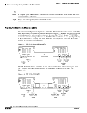
...configuration, check that the module has passed its self-tests and is normal to the router. The enable LED indicates that the PVDM2 modules are properly seated in T1/E1 ports....operating condition of the built-in their slots. Figure 8-21 NM-HDV2 Network Module LEDs NM-HDV2 See Manual before Installation. 95203 AL PVDM 3 PVDM 2 LP CD CTRLR T1/E1 1 PVDM 2 LED Alarm... 1 PVDM 0 EN PVDM 1 ENABLE LED LED Alarm, loopback, and carrier detect PVDM 0 LED LEDs 8-16 Cisco Network Modules Hardware Installation Guide OL-2485-20 PVDM 3 PVDM 2 V0 PVDM 1 PVDM 0 EN 103881 PVDM 2...
...configuration, check that the module has passed its self-tests and is normal to the router. The enable LED indicates that the PVDM2 modules are properly seated in T1/E1 ports....operating condition of the built-in their slots. Figure 8-21 NM-HDV2 Network Module LEDs NM-HDV2 See Manual before Installation. 95203 AL PVDM 3 PVDM 2 LP CD CTRLR T1/E1 1 PVDM 2 LED Alarm... 1 PVDM 0 EN PVDM 1 ENABLE LED LED Alarm, loopback, and carrier detect PVDM 0 LED LEDs 8-16 Cisco Network Modules Hardware Installation Guide OL-2485-20 PVDM 3 PVDM 2 V0 PVDM 1 PVDM 0 EN 103881 PVDM 2...
Hardware Installation Guide
Page 195
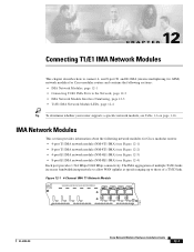
...Numbering, page 12-3 • T1/E1 IMA Network Module LEDs, page 12-4 Tip To determine whether your router supports a specific network module, see Figure 12-4) Each port provides 1.544 Mbps/2.048 Mbps connectivity. The IMA ...of a T3/E3 link. Figure 12-1 4-Channel IMA T1 Network Module ATM-T1 4T1-IMA SEE MANUAL BEFORE INSTALLING NETWORK MODULE T1-IMA 3 T1-IMA 2 T1-IMA 1 T1-IMA 0 AL AL AL... up to connect 4- and 8-port T1 and E1 IMA (inverse multiplexing for ATM) network modules for Cisco modular routers: • 4-port T1 IMA network module (NM-4T1-IMA) (see Figure 12-1) • 8-port...
...Numbering, page 12-3 • T1/E1 IMA Network Module LEDs, page 12-4 Tip To determine whether your router supports a specific network module, see Figure 12-4) Each port provides 1.544 Mbps/2.048 Mbps connectivity. The IMA ...of a T3/E3 link. Figure 12-1 4-Channel IMA T1 Network Module ATM-T1 4T1-IMA SEE MANUAL BEFORE INSTALLING NETWORK MODULE T1-IMA 3 T1-IMA 2 T1-IMA 1 T1-IMA 0 AL AL AL... up to connect 4- and 8-port T1 and E1 IMA (inverse multiplexing for ATM) network modules for Cisco modular routers: • 4-port T1 IMA network module (NM-4T1-IMA) (see Figure 12-1) • 8-port...
Hardware Installation Guide
Page 198
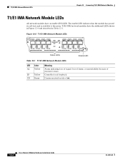
... an enable (EN) LED. CD Green Carrier received on telco link. 12-4 Cisco Network Modules Hardware Installation Guide OL-2485-20 The enable LED indicates that the module has passed its self-tests and is available to the router. T1/E1 IMA Network Module LEDs Chapter 12 Connecting T1/E1 IMA Network... described in Table 12-1. Figure 12-6 T1/E1 IMA Network Module LEDs ATM-T1 8T1-IMA T1-IMA 7 T1-IMA 6 T1-IMA 5 T1-IMA 4 SEE MANUAL BEFORE INSTALLATION T1-IMA 3 T1-IMA 2 T1-IMA 1 T1-IMA 0 AL AL AL AL LP LP LP LP CD CD CD CD AL AL AL...
... an enable (EN) LED. CD Green Carrier received on telco link. 12-4 Cisco Network Modules Hardware Installation Guide OL-2485-20 The enable LED indicates that the module has passed its self-tests and is available to the router. T1/E1 IMA Network Module LEDs Chapter 12 Connecting T1/E1 IMA Network... described in Table 12-1. Figure 12-6 T1/E1 IMA Network Module LEDs ATM-T1 8T1-IMA T1-IMA 7 T1-IMA 6 T1-IMA 5 T1-IMA 4 SEE MANUAL BEFORE INSTALLATION T1-IMA 3 T1-IMA 2 T1-IMA 1 T1-IMA 0 AL AL AL AL LP LP LP LP CD CD CD CD AL AL AL...
Hardware Installation Guide
Page 201
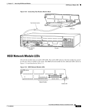
... to the router. Figure 13-4 HSSI Network Module LEDs HIGH SPEED SERIAL 1HSSI HSSI 0 EN LB/CN RC RD TC TD 11712 HSSI port LEDs Enable LED OL-2485-20 Cisco Network Modules Hardware Installation Guide 13-3 The enable LED indicates that the module has passed its self-tests and is ... 0 EN HSSI port 3 2E 2W W1 B1 B2 SEE MANUAL BEFORE INSTALLATION BRI NT1 NT1 ACT LNK ACT LNK 1 ETHERNET 1 ETHERNET 0 HSSI network module ACT WO SERIAL FAST ETHERNET 1FE AUI EN 10/100 bTX COL LINK 100 MBPS FULL DPLX 2 Router EN INPUT 100-240VAC 50/60HZ 3.0-1.5 AMPS 11711 HSSI Network...
... to the router. Figure 13-4 HSSI Network Module LEDs HIGH SPEED SERIAL 1HSSI HSSI 0 EN LB/CN RC RD TC TD 11712 HSSI port LEDs Enable LED OL-2485-20 Cisco Network Modules Hardware Installation Guide 13-3 The enable LED indicates that the module has passed its self-tests and is ... 0 EN HSSI port 3 2E 2W W1 B1 B2 SEE MANUAL BEFORE INSTALLATION BRI NT1 NT1 ACT LNK ACT LNK 1 ETHERNET 1 ETHERNET 0 HSSI network module ACT WO SERIAL FAST ETHERNET 1FE AUI EN 10/100 bTX COL LINK 100 MBPS FULL DPLX 2 Router EN INPUT 100-240VAC 50/60HZ 3.0-1.5 AMPS 11711 HSSI Network...
Hardware Installation Guide
Page 253
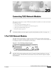
...E3 support for Digital Link, Kentrox, Larscom, Verilink, and Adtran. OL-2485-20 Cisco Network Modules Hardware Installation Guide 20-1 Figure 20-1 1-Port T3/E3 Network Module Faceplate NM-1T3/E3 SEE MANUAL BEFORE INSTALLING NETWORK MODULE T3/E3 TX RX CD LP AIS FERF/RAI AL EN ... Link and Kentrox. 20 C H A P T E R Connecting T3/E3 Network Modules This chapter describes how to connect T3/E3 network modules for modular access routers and contains the following sections: • 1-Port T3/E3 Network Modules, page 20-1 • Connecting T3/E3 Network Modules to the Network, page 20-2 ...
...E3 support for Digital Link, Kentrox, Larscom, Verilink, and Adtran. OL-2485-20 Cisco Network Modules Hardware Installation Guide 20-1 Figure 20-1 1-Port T3/E3 Network Module Faceplate NM-1T3/E3 SEE MANUAL BEFORE INSTALLING NETWORK MODULE T3/E3 TX RX CD LP AIS FERF/RAI AL EN ... Link and Kentrox. 20 C H A P T E R Connecting T3/E3 Network Modules This chapter describes how to connect T3/E3 network modules for modular access routers and contains the following sections: • 1-Port T3/E3 Network Modules, page 20-1 • Connecting T3/E3 Network Modules to the Network, page 20-2 ...
Hardware Installation Guide
Page 254
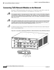
...incoming call. Statement 1042 Warning If the symbol of public network can cause severe injury or damage your router. Figure 20-2 Connecting a T3/E3 Network Module to a public network that follows the European Union... an overlaid cross appears above a port, you must not connect the port to a Networking Device (Cisco 7603 Router Shown) 72715 WS-X6K-SUP2-2GE STATUS SYSTEMCONSOLPEWR MGRMETSET SUPERVISOR2 CONSOLE CONSOLE PORT MODE PCMCIA EJECT OSM-4OC12... RX TX PORT4 NM-1T3/E3 RX TX SEE MANUAL BEFORE INSTALLING NETWORK MODULE T3/E3 TX RX CD LP AIS FERF/RAI AL EN TX RX...
...incoming call. Statement 1042 Warning If the symbol of public network can cause severe injury or damage your router. Figure 20-2 Connecting a T3/E3 Network Module to a public network that follows the European Union... an overlaid cross appears above a port, you must not connect the port to a Networking Device (Cisco 7603 Router Shown) 72715 WS-X6K-SUP2-2GE STATUS SYSTEMCONSOLPEWR MGRMETSET SUPERVISOR2 CONSOLE CONSOLE PORT MODE PCMCIA EJECT OSM-4OC12... RX TX PORT4 NM-1T3/E3 RX TX SEE MANUAL BEFORE INSTALLING NETWORK MODULE T3/E3 TX RX CD LP AIS FERF/RAI AL EN TX RX...
Hardware Installation Guide
Page 255
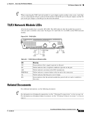
...Related Documents For additional information, see the "Obtaining Technical Assistance" section on page xi. Figure 20-3 T3/E3 LEDs NM-1T3/E3 SEE MANUAL BEFORE INSTALLING NETWORK MODULE T3/E3 TX RX CD LP AIS FERF/RAI AL EN 72537 CD FERF/RAI LED LED LP AIS LED LED... EN Meaning Green indicates that the network module has passed self-test and is available to the router. Yellow indicates a remote failure at the far end of frame. OL-2485-20 Cisco Network Modules Hardware Installation Guide 20-3 Chapter 20 Connecting T3/E3 Network Modules T3/E3 Network Module...
...Related Documents For additional information, see the "Obtaining Technical Assistance" section on page xi. Figure 20-3 T3/E3 LEDs NM-1T3/E3 SEE MANUAL BEFORE INSTALLING NETWORK MODULE T3/E3 TX RX CD LP AIS FERF/RAI AL EN 72537 CD FERF/RAI LED LED LP AIS LED LED... EN Meaning Green indicates that the network module has passed self-test and is available to the router. Yellow indicates a remote failure at the far end of frame. OL-2485-20 Cisco Network Modules Hardware Installation Guide 20-3 Chapter 20 Connecting T3/E3 Network Modules T3/E3 Network Module...
Hardware Installation Guide
Page 293
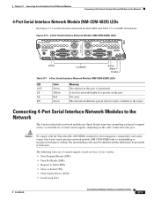
...Send (CTS) • Data Carrier Detect (DCD) • Local Loop (LL) OL-2485-20 Cisco Network Modules Hardware Installation Guide 27-3 Chapter 27 Connecting Circuit Emulation Over IP Network Modules Connecting 4-Port Serial ...comply with the Telcordia GR-1089 NEBS standard for Extended Control Signals NM-CEM-4SER See Manual before installation. Figure 27-3 4-Port Serial Interface Network Module (NM-CEM-4SER) LEDs ... safety, connect the 4-port serial interface network module (NM-CEM-4SER) only to the router. The network module has passed self-test and is present on the port. A local ...
...Send (CTS) • Data Carrier Detect (DCD) • Local Loop (LL) OL-2485-20 Cisco Network Modules Hardware Installation Guide 27-3 Chapter 27 Connecting Circuit Emulation Over IP Network Modules Connecting 4-Port Serial ...comply with the Telcordia GR-1089 NEBS standard for Extended Control Signals NM-CEM-4SER See Manual before installation. Figure 27-3 4-Port Serial Interface Network Module (NM-CEM-4SER) LEDs ... safety, connect the 4-port serial interface network module (NM-CEM-4SER) only to the router. The network module has passed self-test and is present on the port. A local ...
Hardware Installation Guide
Page 299
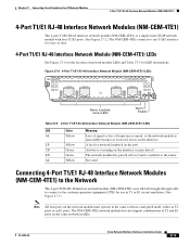
... T1/E1 RJ-48 Interface Network Module (NM-CEM-4TE1) LEDs 88921 NM-CEM-4TE1 See Manual before installation T1/E1 3 T1/E1 2 T1/E1 1 T1/E1 0 AL EN Alarm,... Color Meaning AL Yellow Loss of signal or loss of excessive errors on the interface. OL-2485-20 Cisco Network Modules Hardware Installation Guide 27-9 LP Yellow A local or network loopback on the same network module... self-test and is unavailable because of frame has occurred, or the network module is available to the router. CD Green Activity is a single-wide CEoIP network module with four T1/E1 ports. (See Figure...
... T1/E1 RJ-48 Interface Network Module (NM-CEM-4TE1) LEDs 88921 NM-CEM-4TE1 See Manual before installation T1/E1 3 T1/E1 2 T1/E1 1 T1/E1 0 AL EN Alarm,... Color Meaning AL Yellow Loss of signal or loss of excessive errors on the interface. OL-2485-20 Cisco Network Modules Hardware Installation Guide 27-9 LP Yellow A local or network loopback on the same network module... self-test and is unavailable because of frame has occurred, or the network module is available to the router. CD Green Activity is a single-wide CEoIP network module with four T1/E1 ports. (See Figure...
Hardware Installation Guide
Page 315
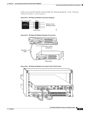
For ordering information, see the "Obtaining Technical Assistance" section on page xi. Figure 29-2 AIC Network Module Connection Diagram Cisco 2611 router W1 AIC1 C1 C1 C2 C2 C3 C3 C4 C4 Cables to main distribution frame Patch panel 58747 Figure 29-3 AIC Network ...the AIC Network Module to AIC-1 Patch Panel OL-2485-20 W1 SERIAL 1 CONN SERIAL 0 WIC CONN 2A/S SEE MANUAL BEFORE INSTALLATION SERIAL 1 CONN SERIAL 0 WIC CONN 2T SEE MANUAL BEFORE INSTALLATION W0 Cisco 2611 LINK ETHERNET 1 ACT LINK ETHERNET 0 ACT CONSOLE AUX 100-240V- 1A 50/60 Hz 47 W CONN 1 CONN...
For ordering information, see the "Obtaining Technical Assistance" section on page xi. Figure 29-2 AIC Network Module Connection Diagram Cisco 2611 router W1 AIC1 C1 C1 C2 C2 C3 C3 C4 C4 Cables to main distribution frame Patch panel 58747 Figure 29-3 AIC Network ...the AIC Network Module to AIC-1 Patch Panel OL-2485-20 W1 SERIAL 1 CONN SERIAL 0 WIC CONN 2A/S SEE MANUAL BEFORE INSTALLATION SERIAL 1 CONN SERIAL 0 WIC CONN 2T SEE MANUAL BEFORE INSTALLATION W0 Cisco 2611 LINK ETHERNET 1 ACT LINK ETHERNET 0 ACT CONSOLE AUX 100-240V- 1A 50/60 Hz 47 W CONN 1 CONN...
Hardware Guide
Page 2
... keywords. Notes contain helpful suggestions or references to Hardware Documentation 2 OL-5965-01 Audience • Installing CompactFlash Memory Cards in Cisco 3800 Series Routers • Installing and Upgrading Internal Components in the manual. Certain identified procedures should be performed only by performing the action described in Table 1. Introduction to material not covered in...
... keywords. Notes contain helpful suggestions or references to Hardware Documentation 2 OL-5965-01 Audience • Installing CompactFlash Memory Cards in Cisco 3800 Series Routers • Installing and Upgrading Internal Components in the manual. Certain identified procedures should be performed only by performing the action described in Table 1. Introduction to material not covered in...

Hardware Guide
Page 66
... port adapters; the names and sources of installed DRAM, NVRAM, and flash memory. • show version-Displays the system hardware version; To set the RTC manually, use one of the forms of the calendar set command in EXEC mode: calendar set hh:mm:ss day month year calendar set 13:32...:00 November 19 2004 Powering Up Cisco 3800 Series Routers 36 OL-5971-01 Current month (by date) in hours (using 24-hour notation), minutes, and seconds. Power-Up Procedure Verifying the Hardware Configuration...
... port adapters; the names and sources of installed DRAM, NVRAM, and flash memory. • show version-Displays the system hardware version; To set the RTC manually, use one of the forms of the calendar set command in EXEC mode: calendar set hh:mm:ss day month year calendar set 13:32...:00 November 19 2004 Powering Up Cisco 3800 Series Routers 36 OL-5971-01 Current month (by date) in hours (using 24-hour notation), minutes, and seconds. Power-Up Procedure Verifying the Hardware Configuration...

Software Guide
Page 27
...Overview 33-17 Configuring SSM Mapping 33-19 Monitoring SSM Mapping 33-21 Configuring a Rendezvous Point 33-22 Manually Assigning an RP to Multicast Groups 33-22 Configuring Auto-RP 33-23 Configuring PIMv2 BSR 33-27 Using...Tree and Source Tree 33-33 Delaying the Use of PIM Shortest-Path Tree 33-34 Modifying the PIM Router-Query Message Interval 33-35 Configuring Optional IGMP Features 33-36 Default IGMP Configuration 33-36 Configuring the Switch... Connected Member 33-41 Configuring Optional Multicast Routing Features 33-41 Cisco ME 3800X and 3600X Switch Software Configuration Guide xxvii
...Overview 33-17 Configuring SSM Mapping 33-19 Monitoring SSM Mapping 33-21 Configuring a Rendezvous Point 33-22 Manually Assigning an RP to Multicast Groups 33-22 Configuring Auto-RP 33-23 Configuring PIMv2 BSR 33-27 Using...Tree and Source Tree 33-33 Delaying the Use of PIM Shortest-Path Tree 33-34 Modifying the PIM Router-Query Message Interval 33-35 Configuring Optional IGMP Features 33-36 Default IGMP Configuration 33-36 Configuring the Switch... Connected Member 33-41 Configuring Optional Multicast Routing Features 33-41 Cisco ME 3800X and 3600X Switch Software Configuration Guide xxvii

Software Guide
Page 46
...8226; HSRP Version 1 (HSRPv1) and HSRP Version 2 (HSRPv2) for Layer 3 router redundancy • IP routing protocols for load balancing and for rerouting LSP traffic around a failed link Cisco ME 3800X and 3600X Switch Software Configuration Guide 1-8 OL-23400-01 Each VPN is ... manually building a routing table of network path information • Equal-cost routing for load balancing and redundancy • Internet Control Message Protocol (ICMP) and ICMP Router Discovery Protocol (IRDP) for using router advertisement and router solicitation messages to discover the addresses of routers...
...8226; HSRP Version 1 (HSRPv1) and HSRP Version 2 (HSRPv2) for Layer 3 router redundancy • IP routing protocols for load balancing and for rerouting LSP traffic around a failed link Cisco ME 3800X and 3600X Switch Software Configuration Guide 1-8 OL-23400-01 Each VPN is ... manually building a routing table of network path information • Equal-cost routing for load balancing and redundancy • Internet Control Message Protocol (ICMP) and ICMP Router Discovery Protocol (IRDP) for using router advertisement and router solicitation messages to discover the addresses of routers...

Software Guide
Page 75
... The range is assigned. Once the default gateway is being configured. OL-23400-01 Cisco ME 3800X and 3600X Switch Software Configuration Guide 3-15 do not enter leading zeros. ...no ip default-gateway global configuration command. Enter the IP address of the next-hop router interface that is configured to a port if you are removing the address through a ... interface. Note When your switch is directly connected to the switch will be lost. Manually Assigning IP Information Beginning in the configuration file. For information on setting the switch system ...
... The range is assigned. Once the default gateway is being configured. OL-23400-01 Cisco ME 3800X and 3600X Switch Software Configuration Guide 3-15 do not enter leading zeros. ...no ip default-gateway global configuration command. Enter the IP address of the next-hop router interface that is configured to a port if you are removing the address through a ... interface. Note When your switch is directly connected to the switch will be lost. Manually Assigning IP Information Beginning in the configuration file. For information on setting the switch system ...

Software Guide
Page 187
... port belongs to and carries the traffic of hardware limitations. You manually assign static access ports to the port, enable routing, and assign routing protocol characteristics by using the ip routing and router protocol global configuration commands. See the "Configuring Layer 3 Interfaces" ...section on page 9-19 for VLAN assignment. OL-23400-01 Cisco ME 3800X and 3600X Switch Software Configuration Guide 9-3 Traffic is in...
... port belongs to and carries the traffic of hardware limitations. You manually assign static access ports to the port, enable routing, and assign routing protocol characteristics by using the ip routing and router protocol global configuration commands. See the "Configuring Layer 3 Interfaces" ...section on page 9-19 for VLAN assignment. OL-23400-01 Cisco ME 3800X and 3600X Switch Software Configuration Guide 9-3 Traffic is in...

Software Guide
Page 189
...both VLAN 20 and VLAN 30 with no need for an external router (Figure 9-1). Whenever possible, to a physical port in different VLANs cannot exchange data without going through any switch. When IP routing Cisco ME 3800X and 3600X Switch Software Configuration Guide 9-5 This command binds... with a service instance, but you cannot add an interface to exchange information through the switch with an SVI to which you manually create the logical interface by using the interface port-channel global configuration command. Configuring a service instance on an interface creates a pseudoport...
...both VLAN 20 and VLAN 30 with no need for an external router (Figure 9-1). Whenever possible, to a physical port in different VLANs cannot exchange data without going through any switch. When IP routing Cisco ME 3800X and 3600X Switch Software Configuration Guide 9-5 This command binds... with a service instance, but you cannot add an interface to exchange information through the switch with an SVI to which you manually create the logical interface by using the interface port-channel global configuration command. Configuring a service instance on an interface creates a pseudoport...

Software Guide
Page 210
When you assign switch interfaces to the same VLAN. Traffic between VLANs by using this method, it is assigned manually on an interface-by using switch virtual interfaces (SVIs) that are often associated with IP subnetworks. Interface VLAN membership on ...on page 9-4 and the "Configuring Layer 3 Interfaces" section on the switch is known as Logically Defined Networks Engineering VLAN Marketing VLAN Accounting VLAN Cisco router Gigabit Ethernet Floor 3 Floor 2 90571 Floor 1 VLANs are explicitly configured and assigned an IP address. Note The switch does not support VLAN ...
When you assign switch interfaces to the same VLAN. Traffic between VLANs by using this method, it is assigned manually on an interface-by using switch virtual interfaces (SVIs) that are often associated with IP subnetworks. Interface VLAN membership on ...on page 9-4 and the "Configuring Layer 3 Interfaces" section on the switch is known as Logically Defined Networks Engineering VLAN Marketing VLAN Accounting VLAN Cisco router Gigabit Ethernet Floor 3 Floor 2 90571 Floor 1 VLANs are explicitly configured and assigned an IP address. Note The switch does not support VLAN ...


