Quick Start Guide
Page 2
... , 4 single-wide or 2 double-wide HWICs (high-speed WICs), 2 AIMs, 4 PVDMs (packet voice data modules), 24 ports of IP phone power output, and hardware-based VPN encryption acceleration. This document directs you to Cisco software, is installed. • Cisco 3845 routers provide 4 network module slots, labeled 1, 2, 3, and 4. Cisco 3825 routers also support 1 optional small form-factor pluggable (SFP...
... , 4 single-wide or 2 double-wide HWICs (high-speed WICs), 2 AIMs, 4 PVDMs (packet voice data modules), 24 ports of IP phone power output, and hardware-based VPN encryption acceleration. This document directs you to Cisco software, is installed. • Cisco 3845 routers provide 4 network module slots, labeled 1, 2, 3, and 4. Cisco 3825 routers also support 1 optional small form-factor pluggable (SFP...

Quick Start Guide
Page 29
... series routers. The lower slot is numbered 2. The Cisco 3845 router has four slots: 1 at lower right, 2 at lower left . See the Cisco Network Modules Hardware Installation Guide for Cisco 3800 series routers is identified in this section. The interfaces listed are not listed. 2. Typical examples are network modules, interface cards (VICs, WICs, HWICs, and AIMs) and PVDMs. 7 Port Numbering...
... series routers. The lower slot is numbered 2. The Cisco 3845 router has four slots: 1 at lower right, 2 at lower left . See the Cisco Network Modules Hardware Installation Guide for Cisco 3800 series routers is identified in this section. The interfaces listed are not listed. 2. Typical examples are network modules, interface cards (VICs, WICs, HWICs, and AIMs) and PVDMs. 7 Port Numbering...
Hardware Installation Guide
Page 145
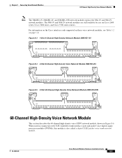
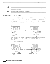
...Density Network Module (NM-HD-1V) NM-HD -1V V0 EN 89033 Figure 8-4 2-Slot 8-Channel High-Density Voice Network Module (NM-HD-2V) NM-HD -2V V1 V0 EN 89034 Figure 8-5 2-Slot 48-Channel High-Density Voice Network Module (NM-HD-2VE) NM-HD -2VE V1 V0...digital signal processor modules (PVDMs), this module is also called a digital T1/E1 packet voice trunk network module. When used in Figure 8-6. For information on the Cisco interface cards supported on these voice network modules, see Table 1-2 on Cisco 2600 series, Cisco 3600 series, and Cisco 3700 series routers. Chapter 8 Connecting ...
...Density Network Module (NM-HD-1V) NM-HD -1V V0 EN 89033 Figure 8-4 2-Slot 8-Channel High-Density Voice Network Module (NM-HD-2V) NM-HD -2V V1 V0 EN 89034 Figure 8-5 2-Slot 48-Channel High-Density Voice Network Module (NM-HD-2VE) NM-HD -2VE V1 V0...digital signal processor modules (PVDMs), this module is also called a digital T1/E1 packet voice trunk network module. When used in Figure 8-6. For information on the Cisco interface cards supported on these voice network modules, see Table 1-2 on Cisco 2600 series, Cisco 3600 series, and Cisco 3700 series routers. Chapter 8 Connecting ...
Hardware Installation Guide
Page 146
...module only, and use PVDM2 modules with a single 72-pin PVDM. The PVDMs must be installed starting from slot 0. Note PVDM and PVDM2 modules are required to connect to 12 channels per PVDM (60 channels for cards with 5 PVDMs) for LAN access. Cisco Network Modules Hardware Installation Guide 8-4 OL-2485-20 Packet Voice ...interface cards (VWIC-1MFT-T1, VWIC-2MFT-T1, and VWIC-2MFT-T1-DI) are supported using channel-associated signaling (CAS). In Cisco 3620 and Cisco 3640 routers, at least one or two T1/E1 line interfaces) can be filled with the NM-HDV2 network module only. In...
...module only, and use PVDM2 modules with a single 72-pin PVDM. The PVDMs must be installed starting from slot 0. Note PVDM and PVDM2 modules are required to connect to 12 channels per PVDM (60 channels for cards with 5 PVDMs) for LAN access. Cisco Network Modules Hardware Installation Guide 8-4 OL-2485-20 Packet Voice ...interface cards (VWIC-1MFT-T1, VWIC-2MFT-T1, and VWIC-2MFT-T1-DI) are supported using channel-associated signaling (CAS). In Cisco 3620 and Cisco 3640 routers, at least one or two T1/E1 line interfaces) can be filled with the NM-HDV2 network module only. In...
Hardware Installation Guide
Page 147
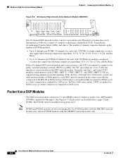
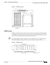
PVDM cards are manufactured with the connector edge down, the polarization notch near the front of the chassis, and the component side facing the right side ... holes 22953 OL-2485-20 Connector edge Polarization notch Cisco Network Modules Hardware Installation Guide 8-5 Figure 8-8 shows the polarization notch and alignment holes on a PVDM card. Chapter 8 Connecting Voice Network Modules Figure 8-7 PVDM Slot Locations 43210 60-Channel High-Density Voice Network Module 22955 PVDM slots PVDM Orientation PVDMs are installed with a polarization notch to ensure proper orientation...
PVDM cards are manufactured with the connector edge down, the polarization notch near the front of the chassis, and the component side facing the right side ... holes 22953 OL-2485-20 Connector edge Polarization notch Cisco Network Modules Hardware Installation Guide 8-5 Figure 8-8 shows the polarization notch and alignment holes on a PVDM card. Chapter 8 Connecting Voice Network Modules Figure 8-7 PVDM Slot Locations 43210 60-Channel High-Density Voice Network Module 22955 PVDM slots PVDM Orientation PVDMs are installed with a polarization notch to ensure proper orientation...
Hardware Installation Guide
Page 149
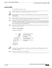
...near the front of the chassis, and the component side away from vertical. 2. The socket guide posts fit through Step 4 for each PVDM is properly seated, the socket guide posts fit through the alignment holes, and the connector springs click into the socket at an angle, tilted... side of the chassis. Ensure that the alignment holes (as shown in the PVDM. 4. OL-2485-20 Cisco Network Modules Hardware Installation Guide 8-7 Step 2 Step 3 Step 4 Hold the PVDM with bank 0, insert the PVDM into the connector slot at an angle from you, with the connector edge at the bottom. (See...
...near the front of the chassis, and the component side away from vertical. 2. The socket guide posts fit through Step 4 for each PVDM is properly seated, the socket guide posts fit through the alignment holes, and the connector springs click into the socket at an angle, tilted... side of the chassis. Ensure that the alignment holes (as shown in the PVDM. 4. OL-2485-20 Cisco Network Modules Hardware Installation Guide 8-7 Step 2 Step 3 Step 4 Hold the PVDM with bank 0, insert the PVDM into the connector slot at an angle from you, with the connector edge at the bottom. (See...
Hardware Installation Guide
Page 150
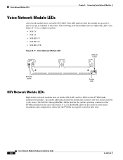
... module has passed its self-tests and is available to the router. Cisco Network Modules Hardware Installation Guide 8-8 OL-2485-20 This LED indicates that the module has passed its self-tests and is available to the router. The BANK 0 through 4. The following network modules have no...card. (See Figure 8-12.) If the BANK LEDs do not come on after initial installation and configuration, check that the PVDMs are properly seated in their slots. Voice Network Module LEDs Chapter 8 Connecting Voice Network Modules Voice Network Module LEDs All network modules have an enable (EN...
... module has passed its self-tests and is available to the router. Cisco Network Modules Hardware Installation Guide 8-8 OL-2485-20 This LED indicates that the module has passed its self-tests and is available to the router. The BANK 0 through 4. The following network modules have no...card. (See Figure 8-12.) If the BANK LEDs do not come on after initial installation and configuration, check that the PVDMs are properly seated in their slots. Voice Network Module LEDs Chapter 8 Connecting Voice Network Modules Voice Network Module LEDs All network modules have an enable (EN...
Hardware Installation Guide
Page 151
...with two built-in T1/E1 ports, shown in Figure 8-15 These three base-board SKUs also include a single VIC or VWIC slot for Foreign Exchange Station (FXS), Foreign Exchange Office (FXO) or centralized automated message accounting trunk protocol (CAMA), receive and transmit (E&M), ...Direct Inward Dial (DID), Basic Rate Interface (BRI), or E1/T1 interface cards. PVDM 3 PVDM 2 V0 PVDM 1 PVDM 0 EN 95196 OL-2485-20 Cisco Network Modules Hardware Installation Guide 8-9 Figure 8-13 NM-HDV2 NM-HDV2 See Manual before Installation. Chapter 8 Connecting Voice ...
...with two built-in T1/E1 ports, shown in Figure 8-15 These three base-board SKUs also include a single VIC or VWIC slot for Foreign Exchange Station (FXS), Foreign Exchange Office (FXO) or centralized automated message accounting trunk protocol (CAMA), receive and transmit (E&M), ...Direct Inward Dial (DID), Basic Rate Interface (BRI), or E1/T1 interface cards. PVDM 3 PVDM 2 V0 PVDM 1 PVDM 0 EN 95196 OL-2485-20 Cisco Network Modules Hardware Installation Guide 8-9 Figure 8-13 NM-HDV2 NM-HDV2 See Manual before Installation. Chapter 8 Connecting Voice ...
Hardware Installation Guide
Page 158
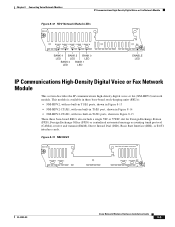
...Step 2 through 3. The PVDM 0 through PVDM 3 LEDs indicate the current operating condition of the built-in their slots. IP Communications High-Density ... If the PVDM LEDs are not green after initial installation and configuration, check that the module has passed its self-tests and is normal to the router. The enable...PVDM 1 PVDM 0 EN PVDM 1 ENABLE LED LED Alarm, loopback, and carrier detect PVDM 0 LED LEDs 8-16 Cisco Network Modules Hardware Installation Guide OL-2485-20 PVDM 3 PVDM 2 V0 PVDM 1 PVDM 0 EN 103881 PVDM 2 PVDM 3 LED LED PVDM 1 ENABLE LED LED PVDM...
...Step 2 through 3. The PVDM 0 through PVDM 3 LEDs indicate the current operating condition of the built-in their slots. IP Communications High-Density ... If the PVDM LEDs are not green after initial installation and configuration, check that the module has passed its self-tests and is normal to the router. The enable...PVDM 1 PVDM 0 EN PVDM 1 ENABLE LED LED Alarm, loopback, and carrier detect PVDM 0 LED LEDs 8-16 Cisco Network Modules Hardware Installation Guide OL-2485-20 PVDM 3 PVDM 2 V0 PVDM 1 PVDM 0 EN 103881 PVDM 2 PVDM 3 LED LED PVDM 1 ENABLE LED LED PVDM...
Hardware Guide
Page 19
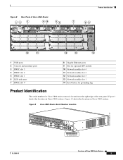
... location on Cisco 3825 routers. Product Identification Figure 8 Rear Panel of Cisco 3845 Router 12 3 CONSOLE 1 0 HWIC 3 AUX 4 15 56 HWIC 1 PVDM 3 PVDM 2 PVDM 1 PVDM 0 AIM ...1 AIM 0 HWIC 2 Do Not Remove During Network Operation CF 7 HWIC 0 4 2 10 11 12 13 89 GE 0/1 SPD LNK SPD LNK SFP GE 0/0 3 CISCO3845 1 14 116844 1 USB ports 2 Console and auxiliary ports 3 HWIC slot 3 4 HWIC slot 2 5 HWIC slot 1 6 LED indicators 7 HWIC slot 0 8 Gigabit Ethernet ports 9 Slot...
... location on Cisco 3825 routers. Product Identification Figure 8 Rear Panel of Cisco 3845 Router 12 3 CONSOLE 1 0 HWIC 3 AUX 4 15 56 HWIC 1 PVDM 3 PVDM 2 PVDM 1 PVDM 0 AIM ...1 AIM 0 HWIC 2 Do Not Remove During Network Operation CF 7 HWIC 0 4 2 10 11 12 13 89 GE 0/1 SPD LNK SPD LNK SFP GE 0/0 3 CISCO3845 1 14 116844 1 USB ports 2 Console and auxiliary ports 3 HWIC slot 3 4 HWIC slot 2 5 HWIC slot 1 6 LED indicators 7 HWIC slot 0 8 Gigabit Ethernet ports 9 Slot...

Hardware Guide
Page 23
... (AIMs) and packet voice data modules (PVDMs) install into connectors on network modules inserted into the router's rear panel, labeled 0/0 and 0/1. Built-In Ports Cisco 3800 series routers have two Gigabit Ethernet ports built into a router slot are not part of the Cisco 3845 router. For example, port 1 of Cisco 3800 Series Routers 9 All slots must be identified as labeled on the...
... (AIMs) and packet voice data modules (PVDMs) install into connectors on network modules inserted into the router's rear panel, labeled 0/0 and 0/1. Built-In Ports Cisco 3800 series routers have two Gigabit Ethernet ports built into a router slot are not part of the Cisco 3845 router. For example, port 1 of Cisco 3800 Series Routers 9 All slots must be identified as labeled on the...