Hardware Installation Guide
Page 5
... and NIC Cards 5 Cabling Distance 5 Clearing the Switch IP Address and Configuration 6 Replacing a Failed Stack Member 6 Finding the Switch Serial Number 7 1 Technical Specifications 1 1 Connector and Cable Specifications 1 Connector Specifications 1 10/100 and 10/100/1000 Ports 2 100BASE-FX Ports 2 SFP Module Ports 3 XENPAK Module Ports (Catalyst 3750G-16TD Switch) 4 Console Port 4 Cable and Adapter Specifications 5 SFP...
... and NIC Cards 5 Cabling Distance 5 Clearing the Switch IP Address and Configuration 6 Replacing a Failed Stack Member 6 Finding the Switch Serial Number 7 1 Technical Specifications 1 1 Connector and Cable Specifications 1 Connector Specifications 1 10/100 and 10/100/1000 Ports 2 100BASE-FX Ports 2 SFP Module Ports 3 XENPAK Module Ports (Catalyst 3750G-16TD Switch) 4 Console Port 4 Cable and Adapter Specifications 5 SFP...

Hardware Installation Guide
Page 23
.... XENPAK Module Slot (Catalyst 3750G-16TD Switch) The Catalyst 3750G-16TD switch uses 10-Gigabit Ethernet XENPAK modules to establish connections to other switches. You can use the SFP modules for Gigabit uplink connections to monitor switch activity and its performance...replaceable, providing the uplink interfaces when inserted in an SFP module slot. The switch software configuration guide describes how to use a Category 5 or higher cable with LC or MT-RJ connectors to connect to configure and monitor individual switches and switch clusters. OL-6336-10 Catalyst 3750 Switch...
.... XENPAK Module Slot (Catalyst 3750G-16TD Switch) The Catalyst 3750G-16TD switch uses 10-Gigabit Ethernet XENPAK modules to establish connections to other switches. You can use the SFP modules for Gigabit uplink connections to monitor switch activity and its performance...replaceable, providing the uplink interfaces when inserted in an SFP module slot. The switch software configuration guide describes how to use a Category 5 or higher cable with LC or MT-RJ connectors to connect to configure and monitor individual switches and switch clusters. OL-6336-10 Catalyst 3750 Switch...

Hardware Installation Guide
Page 42
... unit might have more than one power supply connection. Statement 1030 Warning Ultimate disposal of : 45•C Statement 1047 Catalyst 3750 Switch Hardware Installation Guide 2-4 OL-6336-10 Statement 1019 Warning A readily accessible two-poled disconnect device must be incorporated in ... of a suitably installed ground conductor. Statement 1028 Warning Only trained and qualified personnel should be handled according to install, replace, or service this product should be accessed only through an approved network termination unit with integral circuit protection: 10/100/1000...
... unit might have more than one power supply connection. Statement 1030 Warning Ultimate disposal of : 45•C Statement 1047 Catalyst 3750 Switch Hardware Installation Guide 2-4 OL-6336-10 Statement 1019 Warning A readily accessible two-poled disconnect device must be incorporated in ... of a suitably installed ground conductor. Statement 1028 Warning Only trained and qualified personnel should be handled according to install, replace, or service this product should be accessed only through an approved network termination unit with integral circuit protection: 10/100/1000...

Hardware Installation Guide
Page 43
Before you work on Power over Ethernet (PoE) circuits if interconnections are made aware of explosion if the battery is replaced incorrectly. Statement 1071 Warning Voltages that could cause bodily injury. Note The grounding architecture of each warning to locate its translation ..., PoE or non-PoE 10/100/1000 Ethernet port cables that accompanied this product is the danger of the hazard. Catalyst 3750G Integrated Wireless LAN Controller Switches This warning applies only to the nearest rack metal hardware. You are made using such interconnection methods, unless the exposed...
Before you work on Power over Ethernet (PoE) circuits if interconnections are made aware of explosion if the battery is replaced incorrectly. Statement 1071 Warning Voltages that could cause bodily injury. Note The grounding architecture of each warning to locate its translation ..., PoE or non-PoE 10/100/1000 Ethernet port cables that accompanied this product is the danger of the hazard. Catalyst 3750G Integrated Wireless LAN Controller Switches This warning applies only to the nearest rack metal hardware. You are made using such interconnection methods, unless the exposed...
Hardware Installation Guide
Page 69
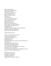
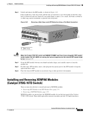
Secure the screws tightly. Step 4 Insert the other end of the cable into the connector of the other switch, and secure the screws tightly. OL-6336-10 Catalyst 3750 Switch Hardware Installation Guide 2-31 Figure 2-44 Inserting the StackWise Cable in a StackWise Port STACK 1 STACK 2 CONSOLE 132362 ...Cisco-approved StackWise cable to align the connector correctly. Make sure that you need to remove the StackWise cable from the connector, make sure to protect them from the StackWise port. When you also remove the correct screws from dust when you are not using them. Replace...
Secure the screws tightly. Step 4 Insert the other end of the cable into the connector of the other switch, and secure the screws tightly. OL-6336-10 Catalyst 3750 Switch Hardware Installation Guide 2-31 Figure 2-44 Inserting the StackWise Cable in a StackWise Port STACK 1 STACK 2 CONSOLE 132362 ...Cisco-approved StackWise cable to align the connector correctly. Make sure that you need to remove the StackWise cable from the connector, make sure to protect them from the StackWise port. When you also remove the correct screws from dust when you are not using them. Replace...
Hardware Installation Guide
Page 71
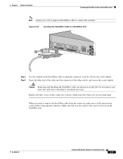
... exceed the stipulated cable length for reliable communications. Note On some SFP modules, the send and receive (TX and RX) markings might be replaced by arrows that identify the top side of the connection, either send or receive (TX or RX). Step 2 Find the send (TX).... See the Catalyst 3750 release notes for Cisco to a bare metal surface on installing, removing, and cabling the SFP module, see your wrist and to identify and validate that has a bale-clasp latch. Each SFP module has an internal serial EEPROM that the Catalyst 3750 switch supports. Do ...
... exceed the stipulated cable length for reliable communications. Note On some SFP modules, the send and receive (TX and RX) markings might be replaced by arrows that identify the top side of the connection, either send or receive (TX or RX). Step 2 Find the send (TX).... See the Catalyst 3750 release notes for Cisco to a bare metal surface on installing, removing, and cabling the SFP module, see your wrist and to identify and validate that has a bale-clasp latch. Each SFP module has an internal serial EEPROM that the Catalyst 3750 switch supports. Do ...
Hardware Installation Guide
Page 73
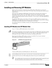
... a Flat-Blade Screwdriver 86554 13 X 14 15 16 17 18 19 20 21 22 23 24 23X X 24X Catalyst 3750 SERIES 1 2 1 1 Bale clasp Warning When the Catalyst 3750-12S switch and 100BASE-FX MMF small form-factor pluggable (SFP) module (model number GLC-GE-100FX) are inserted into the ...optical ports of the Catalyst 3750G-16TD switch. For fiber-optic SFP modules, insert a dust plug into the XENPAK module slot on the front panel of the SFP module to keep the optical interfaces clean. These field-replaceable transceiver modules provide 10-Gigabit interfaces. If the...
... a Flat-Blade Screwdriver 86554 13 X 14 15 16 17 18 19 20 21 22 23 24 23X X 24X Catalyst 3750 SERIES 1 2 1 1 Bale clasp Warning When the Catalyst 3750-12S switch and 100BASE-FX MMF small form-factor pluggable (SFP) module (model number GLC-GE-100FX) are inserted into the ...optical ports of the Catalyst 3750G-16TD switch. For fiber-optic SFP modules, insert a dust plug into the XENPAK module slot on the front panel of the SFP module to keep the optical interfaces clean. These field-replaceable transceiver modules provide 10-Gigabit interfaces. If the...

Hardware Installation Guide
Page 77
...normal board and component handling procedures. OL-6336-10 Catalyst 3750 Switch Hardware Installation Guide 2-39 Chapter 2 Switch Installation Connecting to the 10/100 and 10/100/1000 Ports Figure 2-54 Replacing the XENPAK Module Slot Cover 1 Catalyst 3750 series 1 104765 2 1 Phillips-head screw... 2 Module slot cover Connecting to the 10/100 and 10/100/1000 Ports The switch 10/100 and 10/100/1000 ports configure themselves to either automatically provide PoE when a Cisco IP Phone, Cisco...
...normal board and component handling procedures. OL-6336-10 Catalyst 3750 Switch Hardware Installation Guide 2-39 Chapter 2 Switch Installation Connecting to the 10/100 and 10/100/1000 Ports Figure 2-54 Replacing the XENPAK Module Slot Cover 1 Catalyst 3750 series 1 104765 2 1 Phillips-head screw... 2 Module slot cover Connecting to the 10/100 and 10/100/1000 Ports The switch 10/100 and 10/100/1000 ports configure themselves to either automatically provide PoE when a Cisco IP Phone, Cisco...

Hardware Installation Guide
Page 85
... the switch command reference on Cisco.com or the documentation that came with your SNMP application for troubleshooting problems: • Diagnosing Problems, page 3-1 • Clearing the Switch IP Address and Configuration, page 3-6 • Replacing a Failed Stack Member, page 3-6 • Finding the Switch Serial.... Troubleshooting 3 C H A P T E R The LEDs on the front panel provide troubleshooting information about the switch. For a full description of the switch LEDs, see the "LEDs" section on page 3-5 OL-6336-10 Catalyst 3750 Switch Hardware Installation Guide 3-1
... the switch command reference on Cisco.com or the documentation that came with your SNMP application for troubleshooting problems: • Diagnosing Problems, page 3-1 • Clearing the Switch IP Address and Configuration, page 3-6 • Replacing a Failed Stack Member, page 3-6 • Finding the Switch Serial.... Troubleshooting 3 C H A P T E R The LEDs on the front panel provide troubleshooting information about the switch. For a full description of the switch LEDs, see the "LEDs" section on page 3-5 OL-6336-10 Catalyst 3750 Switch Hardware Installation Guide 3-1

Hardware Installation Guide
Page 87
... • Bad or incorrect SFP module. OL-6336-10 Catalyst 3750 Switch Hardware Installation Guide 3-3 If the link light for the switch. Caution PoE faults are caused when noncompliant cabling or powered ...-disabled, disabled, or shutdown status. Enable auto-MDIX on page 1-12 for all ports. Many legacy powered devices, including older Cisco IP phones and access points that both ends of the LEDs and... Connectors" section on page 1-17 for Cisco to a PoE port. Disconnect and then reconnect the cable. See the "SFP Module Slots" section on the switch, or replace the cable.
... • Bad or incorrect SFP module. OL-6336-10 Catalyst 3750 Switch Hardware Installation Guide 3-3 If the link light for the switch. Caution PoE faults are caused when noncompliant cabling or powered ...-disabled, disabled, or shutdown status. Enable auto-MDIX on page 1-12 for all ports. Many legacy powered devices, including older Cisco IP phones and access points that both ends of the LEDs and... Connectors" section on page 1-17 for Cisco to a PoE port. Disconnect and then reconnect the cable. See the "SFP Module Slots" section on the switch, or replace the cable.
Hardware Installation Guide
Page 88
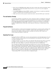
Replace the suspect module with a known good module. Verify that all you have properly cleaned and securely connected all fiber-optic connections. Port and Interface Settings An obvious but the switch does not receive the traffic that might appear to check the port or module error-disabled, ...(the default) and an aggressive mode. Ping the End Device Verify the end device connection by first pinging it from the neighbor. Catalyst 3750 Switch Hardware Installation Guide 3-4 OL-6336-10 If necessary, re-enable the port or the interface. A broken fiber-optic cable, other ...
Replace the suspect module with a known good module. Verify that all you have properly cleaned and securely connected all fiber-optic connections. Port and Interface Settings An obvious but the switch does not receive the traffic that might appear to check the port or module error-disabled, ...(the default) and an aggressive mode. Ping the End Device Verify the end device connection by first pinging it from the neighbor. Catalyst 3750 Switch Hardware Installation Guide 3-4 OL-6336-10 If necessary, re-enable the port or the interface. A broken fiber-optic cable, other ...
Hardware Installation Guide
Page 90
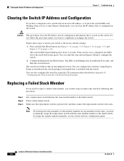
... any members in Appendix D, "Configuring the Switch with the CLI-Based Setup Program." Catalyst 3750 Switch Hardware Installation Guide 3-6 OL-6336-10 Press and hold the Mode button (see the switch software configuration guide. Continue holding down the Mode button. Make sure the replacement switch is powered off the failed switch. To assign the member number manually...
... any members in Appendix D, "Configuring the Switch with the CLI-Based Setup Program." Catalyst 3750 Switch Hardware Installation Guide 3-6 OL-6336-10 Press and hold the Mode button (see the switch software configuration guide. Continue holding down the Mode button. Make sure the replacement switch is powered off the failed switch. To assign the member number manually...

Hardware Installation Guide
Page 91
... replacement switch. Use these figures to get the serial number. • Figure 3-1, Catalyst 3750-24FS and 3750V2-24FS Switch Serial Number Location • Figure 3-2, Catalyst 3750G-12S and 3750-12S-SD Switch Serial Number Location • Figure 3-3, Catalyst 3750G-16TD Switch Serial Number Location • Figure 3-4, Catalyst 3750-24PS Switch Serial Number Location • Figure 3-5, Catalyst 3750G-24PS and 3750G-24TS-1U Switches Serial Number Location • Figure 3-6, Catalyst 3750G...
... replacement switch. Use these figures to get the serial number. • Figure 3-1, Catalyst 3750-24FS and 3750V2-24FS Switch Serial Number Location • Figure 3-2, Catalyst 3750G-12S and 3750-12S-SD Switch Serial Number Location • Figure 3-3, Catalyst 3750G-16TD Switch Serial Number Location • Figure 3-4, Catalyst 3750-24PS Switch Serial Number Location • Figure 3-5, Catalyst 3750G-24PS and 3750G-24TS-1U Switches Serial Number Location • Figure 3-6, Catalyst 3750G...

Hardware Installation Guide
Page 122
... DC-input power source, follow these steps: Step 1 Apply tape to the circuit-breaker switch handle, and move the circuit-breaker handle to install, replace, or service this range, the switch might not operate properly or might be installed with all applicable codes. Connecting to DC Power...from -36 to -72 VDC. Statement 1030 Caution You must comply with 5 A-branch-circuit protection. Note This installation must connect the Catalyst 3750G-12S-SD switch only to a DC-input power source that the protective device is rated not greater than: 5 A Statement 1005 Warning Only trained ...
... DC-input power source, follow these steps: Step 1 Apply tape to the circuit-breaker switch handle, and move the circuit-breaker handle to install, replace, or service this range, the switch might not operate properly or might be installed with all applicable codes. Connecting to DC Power...from -36 to -72 VDC. Statement 1030 Caution You must comply with 5 A-branch-circuit protection. Note This installation must connect the Catalyst 3750G-12S-SD switch only to a DC-input power source that the protective device is rated not greater than: 5 A Statement 1005 Warning Only trained ...