
Installation Guide
Page 6
... Rear-Panel Description 1-21 Power Connectors 1-22 Internal Power Supply Connector 1-23 Cisco RPS Connector 1-23 Console Port 1-24 Management Options 1-24 Network Configuration Examples 1-25 Design Concepts for Installation 2-2 Warnings 2-2 EMC Regulatory Statements 2-5 U.S.A. 2-5 Taiwan 2-5 Japan 2-6 Korea 2-6 Hungary 2-7 Installation Guidelines 2-7 Verifying Package Contents 2-8 Catalyst 3500 Series XL Hardware Installation Guide vi 78-6456-03
... Rear-Panel Description 1-21 Power Connectors 1-22 Internal Power Supply Connector 1-23 Cisco RPS Connector 1-23 Console Port 1-24 Management Options 1-24 Network Configuration Examples 1-25 Design Concepts for Installation 2-2 Warnings 2-2 EMC Regulatory Statements 2-5 U.S.A. 2-5 Taiwan 2-5 Japan 2-6 Korea 2-6 Hungary 2-7 Installation Guidelines 2-7 Verifying Package Contents 2-8 Catalyst 3500 Series XL Hardware Installation Guide vi 78-6456-03

Installation Guide
Page 7
...Switch on a Wall 2-15 Attaching the Brackets to the Switch 2-15 Attaching the Switch to a Wall 2-16 Installing the Switch on a Table or Shelf 2-17 Powering On the Switch... and Running POST 2-17 Connecting to the 10/100 Ports 2-18 Connecting to the GBIC Module Ports 2-20 Connecting to a 1000BaseX GBIC Module Port 2-21 Connecting to a GigaStack GBIC Module Port 2-22 Connecting a PC or Terminal to the Console Port 2-23 Assigning Switch... Information 2-24 Using the Setup Program 2-25 Using BOOTP ...
...Switch on a Wall 2-15 Attaching the Brackets to the Switch 2-15 Attaching the Switch to a Wall 2-16 Installing the Switch on a Table or Shelf 2-17 Powering On the Switch... and Running POST 2-17 Connecting to the 10/100 Ports 2-18 Connecting to the GBIC Module Ports 2-20 Connecting to a 1000BaseX GBIC Module Port 2-21 Connecting to a GigaStack GBIC Module Port 2-22 Connecting a PC or Terminal to the Console Port 2-23 Assigning Switch... Information 2-24 Using the Setup Program 2-25 Using BOOTP ...

Installation Guide
Page 9
INDEX Grounded Equipment Warning C-23 Supply Circuit Warning C-24 No On/Off Switch Warning C-25 Power Supply Warning C-27 Work During Lightning Activity Warning C-30 Product Disposal Warning C-31 Chassis Warning-Rack-Mounting and Servicing C-33 Chassis Power Connection Warning C-38 Shock Hazard from Interconnections Warning C-41 Contents 78-6456-03 Catalyst 3500 Series XL Hardware Installation Guide ix
INDEX Grounded Equipment Warning C-23 Supply Circuit Warning C-24 No On/Off Switch Warning C-25 Power Supply Warning C-27 Work During Lightning Activity Warning C-30 Product Disposal Warning C-31 Chassis Warning-Rack-Mounting and Servicing C-33 Chassis Power Connection Warning C-38 Shock Hazard from Interconnections Warning C-41 Contents 78-6456-03 Catalyst 3500 Series XL Hardware Installation Guide ix
Installation Guide
Page 20
... as an online starting point for troubleshooting and resolving technical issues with Cisco products and technologies. If you have a valid service contract but do Catalyst 3500 Series XL Hardware Installation Guide xx 78-6456-04 The Cisco TAC website is available 24 hours a day, 365 days a year. Obtaining Technical Assistance Preface Documentation Feedback You...
... as an online starting point for troubleshooting and resolving technical issues with Cisco products and technologies. If you have a valid service contract but do Catalyst 3500 Series XL Hardware Installation Guide xx 78-6456-04 The Cisco TAC website is available 24 hours a day, 365 days a year. Obtaining Technical Assistance Preface Documentation Feedback You...

Installation Guide
Page 26
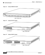
Features Chapter 1 Product Overview Figure 1-1 Catalyst 3500 Series XL Switches Switch Description WS-C3508G-XL 8 GBIC1-based gigabit module slots 1 SYSTEM 2 3 RPS 4 5 MODE STATUS UTIL DUPLX SPEED 6 7 8 WS-C3512-XL 12 autosensing10/100 Ethernet ports 2 GBIC-based gigabit module slots WS-C3524-XL 24 autosensing 10/100 Ethernet ports 2 fixed GBIC-based gigabit module slots...
Features Chapter 1 Product Overview Figure 1-1 Catalyst 3500 Series XL Switches Switch Description WS-C3508G-XL 8 GBIC1-based gigabit module slots 1 SYSTEM 2 3 RPS 4 5 MODE STATUS UTIL DUPLX SPEED 6 7 8 WS-C3512-XL 12 autosensing10/100 Ethernet ports 2 GBIC-based gigabit module slots WS-C3524-XL 24 autosensing 10/100 Ethernet ports 2 fixed GBIC-based gigabit module slots...

Installation Guide
Page 28
...Chapter 1 Product Overview Table 1-2 Catalyst 3512, 3524, 3524-PWR, and 3548 XL Features Feature Performance and Configuration Description • Autonegotiation of speed and duplex operation on 10/100 Ethernet ports • 12, 24, or 48 10/100 Ethernet ports...switches and servers • 8192 MAC addresses • IEEE 802.1p capable • CGMP to limit the flooding of IP multicast traffic • Broadcast storm control to prevent performance degradation from broadcast storms • SPAN port monitoring on any port • Support for command switch redundancy • Support for Cisco...
...Chapter 1 Product Overview Table 1-2 Catalyst 3512, 3524, 3524-PWR, and 3548 XL Features Feature Performance and Configuration Description • Autonegotiation of speed and duplex operation on 10/100 Ethernet ports • 12, 24, or 48 10/100 Ethernet ports...switches and servers • 8192 MAC addresses • IEEE 802.1p capable • CGMP to limit the flooding of IP multicast traffic • Broadcast storm control to prevent performance degradation from broadcast storms • SPAN port monitoring on any port • Support for command switch redundancy • Support for Cisco...

Installation Guide
Page 29
... label that operates on AC input and supplies DC output to the Catalyst 3524-PWR XL switch Inline Power (Catalyst 3524-PWR XL switch only) • Ability to provide inline power for Cisco IP Phones from all 24 10/100 Ethernet ports • Auto-detection and control of inline... SNMP Power Redundancy • Connection for optional Cisco RPS 600 that operates on AC input and supplies DC output to the Catalyst 3512, 3524, and 3548 XL switches • Connection for managing switch clusters or an individual switch through Visual Switch Manager (VSM) Front-Panel Description The front panel...
... label that operates on AC input and supplies DC output to the Catalyst 3524-PWR XL switch Inline Power (Catalyst 3524-PWR XL switch only) • Ability to provide inline power for Cisco IP Phones from all 24 10/100 Ethernet ports • Auto-detection and control of inline... SNMP Power Redundancy • Connection for optional Cisco RPS 600 that operates on AC input and supplies DC output to the Catalyst 3512, 3524, and 3548 XL switches • Connection for managing switch clusters or an individual switch through Visual Switch Manager (VSM) Front-Panel Description The front panel...
Installation Guide
Page 30
... 1X 34 56 78 SYSTEM MODE RPS 2X STATUS UTIL DUPLX SPEED 9 10 11 12 11X 12X 10/100 ports Figure 1-4 Catalyst 3524 XL Switch 1 2 GBIC module slots 12 1X 34 56 78 MODE SYSTEM RPS STATUS 2X UTIL DUPLX SPEED 9 10 11 12 11X 12X 13 14 13X 15 ...16 17 18 19 20 21 22 23 24 23X 14X 24X 10/100 ports 1 2 GBIC module slots Catalyst 3500 Series XL Hardware Installation Guide 1-6 26237...
... 1X 34 56 78 SYSTEM MODE RPS 2X STATUS UTIL DUPLX SPEED 9 10 11 12 11X 12X 10/100 ports Figure 1-4 Catalyst 3524 XL Switch 1 2 GBIC module slots 12 1X 34 56 78 MODE SYSTEM RPS STATUS 2X UTIL DUPLX SPEED 9 10 11 12 11X 12X 13 14 13X 15 ...16 17 18 19 20 21 22 23 24 23X 14X 24X 10/100 ports 1 2 GBIC module slots Catalyst 3500 Series XL Hardware Installation Guide 1-6 26237...

Installation Guide
Page 31
...; 10BaseT-compatible devices such as workstations, Cisco IP Phones, and hubs through standard RJ-45 connectors and Category 3, 4, or 5 cabling 78-6456-04 Catalyst 3500 Series XL Hardware Installation Guide 1-7 Port 3 is above port 4, and so on the Catalyst 3512, 3524, 3524-PWR, and 3548 XL switches are the left-most pair. For example... SPEED LINE PWR 9 10 11 12 11X 12X 13 14 13X 15 16 17 18 19 20 21 22 23 24 23X 14X 24X 10/100 inline-power ports Figure 1-6 Catalyst 3548 XL Switch 1 2 GBIC module slots 28010 SYSTEM RPS 12 1X 34 56 78 9 10 11 12 13 14 15 16 15X...
...; 10BaseT-compatible devices such as workstations, Cisco IP Phones, and hubs through standard RJ-45 connectors and Category 3, 4, or 5 cabling 78-6456-04 Catalyst 3500 Series XL Hardware Installation Guide 1-7 Port 3 is above port 4, and so on the Catalyst 3512, 3524, 3524-PWR, and 3548 XL switches are the left-most pair. For example... SPEED LINE PWR 9 10 11 12 11X 12X 13 14 13X 15 16 17 18 19 20 21 22 23 24 23X 14X 24X 10/100 inline-power ports Figure 1-6 Catalyst 3548 XL Switch 1 2 GBIC module slots 28010 SYSTEM RPS 12 1X 34 56 78 9 10 11 12 13 14 15 16 15X...
Installation Guide
Page 44
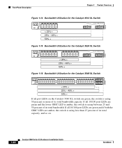
... 13 14 15 16 13X 17 18 19 20 21 22 23 24 15X 14X 16X < 25% + 25% - 49% + 50% + Catalyst 3500 XL 1 2 Figure 1-16 Bandwidth Utilization for the Catalyst 3548 XL Switch 28366 SYSTEM RPS STATUS UTIL DUPLX SPEED MODE 12 1X 3 24 56 78 9 10 11 12 13 14 15 16 15X 17... 18 17X 19 20 21 22 23 24 25 26 27 28 29 31...
... 13 14 15 16 13X 17 18 19 20 21 22 23 24 15X 14X 16X < 25% + 25% - 49% + 50% + Catalyst 3500 XL 1 2 Figure 1-16 Bandwidth Utilization for the Catalyst 3548 XL Switch 28366 SYSTEM RPS STATUS UTIL DUPLX SPEED MODE 12 1X 3 24 56 78 9 10 11 12 13 14 15 16 15X 17... 18 17X 19 20 21 22 23 24 25 26 27 28 29 31...

Installation Guide
Page 48
...DTE adapter if you use to six switches, it supports up to create, monitor, and configure a cluster of four web-based applications that adapter from Cisco. Management Options Catalyst 3500 XL switches offer several management options: • Cisco Cluster Management Suite This suite is ...these applications. 1-24 Catalyst 3500 Series XL Hardware Installation Guide 78-6456-04 You can connect a Catalyst 3500 XL switch to six switches. For console port and adapter pinout information, see the "Cable and Adapter Specifications" section on the Catalyst 3524-PWR XL Switch The Cisco RPS 300 (...
...DTE adapter if you use to six switches, it supports up to create, monitor, and configure a cluster of four web-based applications that adapter from Cisco. Management Options Catalyst 3500 XL switches offer several management options: • Cisco Cluster Management Suite This suite is ...these applications. 1-24 Catalyst 3500 Series XL Hardware Installation Guide 78-6456-04 You can connect a Catalyst 3500 XL switch to six switches. For console port and adapter pinout information, see the "Cable and Adapter Specifications" section on the Catalyst 3524-PWR XL Switch The Cisco RPS 300 (...
Installation Guide
Page 57
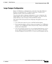
... than 1000 users. Because it can use switch clusters that includes a call processing, routing, and IP phone features and configuration. • Cisco Access gateway (such as the backbone switch. You can aggregate up to the Catalyst 6500 switch. Chapter 1 Product Overview Network Configuration Examples Large Campus Configuration Figure 1-24 illustrates a configuration for access to users in...
... than 1000 users. Because it can use switch clusters that includes a call processing, routing, and IP phone features and configuration. • Cisco Access gateway (such as the backbone switch. You can aggregate up to the Catalyst 6500 switch. Chapter 1 Product Overview Network Configuration Examples Large Campus Configuration Figure 1-24 illustrates a configuration for access to users in...
Installation Guide
Page 58
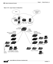
Network Configuration Examples Chapter 1 Product Overview Figure 1-24 Large Campus Configuration WAN IP telephony network or PSTN Cisco CallManager Cisco 7200 Cisco access or 7500 router gateway Servers Catalyst 6500 switch Catalyst 3500 XL and 2900 XL GigaStack cluster 1 Gbps (2 Gbps full duplex) Catalyst 3524-PWR XL GigaStack cluster IP IP AC Workstations running power Cisco SoftPhone software source IP IP Cisco IP Phones IP IP IP Cisco IP Phones 33093 1-34 Catalyst 3500 Series XL Hardware Installation Guide 78-6456-04
Network Configuration Examples Chapter 1 Product Overview Figure 1-24 Large Campus Configuration WAN IP telephony network or PSTN Cisco CallManager Cisco 7200 Cisco access or 7500 router gateway Servers Catalyst 6500 switch Catalyst 3500 XL and 2900 XL GigaStack cluster 1 Gbps (2 Gbps full duplex) Catalyst 3524-PWR XL GigaStack cluster IP IP AC Workstations running power Cisco SoftPhone software source IP IP Cisco IP Phones IP IP IP Cisco IP Phones 33093 1-34 Catalyst 3500 Series XL Hardware Installation Guide 78-6456-04
Installation Guide
Page 67
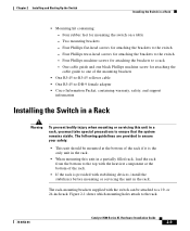
...; One RJ-45-to-DB-9 female adapter • Cisco Information Packet, containing warranty, safety, and support information Installing the Switch in a Rack Warning To prevent bodily injury when mounting ...you must take special precautions to a 19- or 24-inch rack. Four Phillips flat-head screws for attaching the brackets to the switch - The rack-mounting brackets supplied with stabilizing devices... brackets to the switch - Four Phillips machine screws for mounting the switch on a table - Four rubber feet for attaching the brackets to the rack. 78-6456-04 Catalyst 3500 Series XL ...
...; One RJ-45-to-DB-9 female adapter • Cisco Information Packet, containing warranty, safety, and support information Installing the Switch in a Rack Warning To prevent bodily injury when mounting ...you must take special precautions to a 19- or 24-inch rack. Four Phillips flat-head screws for attaching the brackets to the switch - The rack-mounting brackets supplied with stabilizing devices... brackets to the switch - Four Phillips machine screws for mounting the switch on a table - Four rubber feet for attaching the brackets to the rack. 78-6456-04 Catalyst 3500 Series XL ...
Installation Guide
Page 68
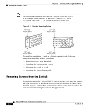
...can also be attached. Figure 2-1 Bracket Mounting Points 19" rack mount point 24" rack mount point 38398 19" rack mount point 24" rack mount point To install the switch in a 19-inch or a 24-inch standard rack, follow the instructions described in these procedures: • ... installed as an example. Installing the Switch in a Rack Chapter 2 Installing and Starting Up the Switch Note The illustrations in this section show the Catalyst 3508G XL switch as shown here. Follow the same procedure for the opposite side. 2-10 Catalyst 3500 Series XL Hardware Installation Guide 78...
...can also be attached. Figure 2-1 Bracket Mounting Points 19" rack mount point 24" rack mount point 38398 19" rack mount point 24" rack mount point To install the switch in a 19-inch or a 24-inch standard rack, follow the instructions described in these procedures: • ... installed as an example. Installing the Switch in a Rack Chapter 2 Installing and Starting Up the Switch Note The illustrations in this section show the Catalyst 3508G XL switch as shown here. Follow the same procedure for the opposite side. 2-10 Catalyst 3500 Series XL Hardware Installation Guide 78...
Installation Guide
Page 69
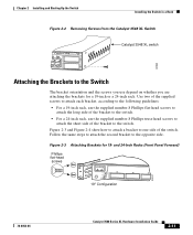
... for a 19-inch or a 24-inch rack. Chapter 2 Installing and Starting Up the Switch Installing the Switch in a Rack Figure 2-2 Removing Screws from the Catalyst 3548 XL Switch 46 47 48 47X 1 2 48X Catalyst 3548 XL switch 30062 Attaching the Brackets to the Switch The bracket orientation and the screws you...to attach the short side of the bracket to the switch. and 24-Inch Racks (Front Panel Forward) Phillips flat-head screws 22437 1 SYSTEM RPS MODE STATUS UTIL DUPLX SPEED 19" Configuration 2 3 78-6456-04 Catalyst 3500 Series XL Hardware Installation Guide 2-11 Follow the...
... for a 19-inch or a 24-inch rack. Chapter 2 Installing and Starting Up the Switch Installing the Switch in a Rack Figure 2-2 Removing Screws from the Catalyst 3548 XL Switch 46 47 48 47X 1 2 48X Catalyst 3548 XL switch 30062 Attaching the Brackets to the Switch The bracket orientation and the screws you...to attach the short side of the bracket to the switch. and 24-Inch Racks (Front Panel Forward) Phillips flat-head screws 22437 1 SYSTEM RPS MODE STATUS UTIL DUPLX SPEED 19" Configuration 2 3 78-6456-04 Catalyst 3500 Series XL Hardware Installation Guide 2-11 Follow the...

Installation Guide
Page 70
... a Rack Chapter 2 Installing and Starting Up the Switch Phillips truss-head screws 1 SYSTEM RPS MODE STATUS UTIL DUPLX SPEED 2 3 24" Configuration Figure 2-4 Attaching Brackets for 19- and 24-Inch Racks (Rear Panel Forward) 22439 22438 DC INPUTS SPECIFIED IFNOMRARNEUMAOL.T+E3P.3OVW***E@R1S4UAP, PLY DC INPUT... +12V***@3A 19" Configuration DC INPUTS SPECIFIED IFNOMRARNEUMAOL.T+E3P.3OVW***E@R1S4UAP, PLY DC INPUT +12V***@3A 24" Configuration Phillips flat-head screws Phillips truss-head screws 22440 2-12 Catalyst 3500 Series XL Hardware Installation Guide 78-6456-04
... a Rack Chapter 2 Installing and Starting Up the Switch Phillips truss-head screws 1 SYSTEM RPS MODE STATUS UTIL DUPLX SPEED 2 3 24" Configuration Figure 2-4 Attaching Brackets for 19- and 24-Inch Racks (Rear Panel Forward) 22439 22438 DC INPUTS SPECIFIED IFNOMRARNEUMAOL.T+E3P.3OVW***E@R1S4UAP, PLY DC INPUT... +12V***@3A 19" Configuration DC INPUTS SPECIFIED IFNOMRARNEUMAOL.T+E3P.3OVW***E@R1S4UAP, PLY DC INPUT +12V***@3A 24" Configuration Phillips flat-head screws Phillips truss-head screws 22440 2-12 Catalyst 3500 Series XL Hardware Installation Guide 78-6456-04
Installation Guide
Page 71
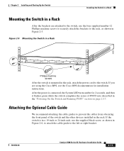
... Installing and Starting Up the Switch Installing the Switch in a Rack Mounting the Switch in a Rack After the brackets are using the Cisco RPS, see the Cisco RPS documentation for 2 seconds, and then it flashes green while the switch completes the series of the switch and the other devices installed ...UTIL 8 DUPLX SPEED Phillips machine screws After the switch is in a 19-inch or 24-inch rack, use the four supplied number-12 Phillips machine screws to securely attach the brackets to the left or right bracket. 78-6456-04 Catalyst 3500 Series XL Hardware Installation Guide 2-13 If ...
... Installing and Starting Up the Switch Installing the Switch in a Rack Mounting the Switch in a Rack After the brackets are using the Cisco RPS, see the Cisco RPS documentation for 2 seconds, and then it flashes green while the switch completes the series of the switch and the other devices installed ...UTIL 8 DUPLX SPEED Phillips machine screws After the switch is in a 19-inch or 24-inch rack, use the four supplied number-12 Phillips machine screws to securely attach the brackets to the left or right bracket. 78-6456-04 Catalyst 3500 Series XL Hardware Installation Guide 2-13 If ...
Installation Guide
Page 72
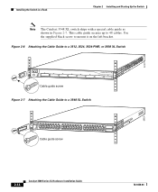
... DUPLX SPEED 6 7 8 Cable guide screw Figure 2-7 Attaching the Cable Guide to a 3548 XL Switch SYSTEM RPS 12 1X 34 56 78 9 10 11 12 13 14 15 16 15X 17 18 17X 19 20 21 22 23 24 25 26 27 28 29 30 31 32 31X 33 34 33X 35 36... 47X STATUS UTIL 1 DUPLEX SPEED 2X MODE 16X 18X 32X 34X 48X 2 Cable guide screw 28324 2-14 Catalyst 3500 Series XL Hardware Installation Guide 78-6456-04 22441 Installing the Switch in a Rack Chapter 2 Installing and Starting Up the Switch Note The Catalyst 3548 XL switch ships with a special cable guide as shown in Figure 2-7.
... DUPLX SPEED 6 7 8 Cable guide screw Figure 2-7 Attaching the Cable Guide to a 3548 XL Switch SYSTEM RPS 12 1X 34 56 78 9 10 11 12 13 14 15 16 15X 17 18 17X 19 20 21 22 23 24 25 26 27 28 29 30 31 32 31X 33 34 33X 35 36... 47X STATUS UTIL 1 DUPLEX SPEED 2X MODE 16X 18X 32X 34X 48X 2 Cable guide screw 28324 2-14 Catalyst 3500 Series XL Hardware Installation Guide 78-6456-04 22441 Installing the Switch in a Rack Chapter 2 Installing and Starting Up the Switch Note The Catalyst 3548 XL switch ships with a special cable guide as shown in Figure 2-7.
Installation Guide
Page 82
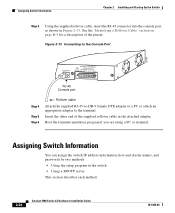
...the other end of the pinout. Boot the terminal-emulation program if you are using a PC or terminal. Assigning Switch Information You can assign the switch IP address information, host and cluster names, and passwords by two methods: • Using the setup program in... a description of the supplied rollover cable in the switch • Using a BOOTP server This section describes each method. 2-24 Catalyst 3500 Series XL Hardware Installation Guide 78-6456-04 Assigning Switch Information Chapter 2 Installing and Starting Up the Switch Step 3 Using the supplied rollover cable, insert the...
...the other end of the pinout. Boot the terminal-emulation program if you are using a PC or terminal. Assigning Switch Information You can assign the switch IP address information, host and cluster names, and passwords by two methods: • Using the setup program in... a description of the supplied rollover cable in the switch • Using a BOOTP server This section describes each method. 2-24 Catalyst 3500 Series XL Hardware Installation Guide 78-6456-04 Assigning Switch Information Chapter 2 Installing and Starting Up the Switch Step 3 Using the supplied rollover cable, insert the...

