

Hardware Installation Guide
Page 42
...Specific Cisco RPS models support specific Catalyst 2900 XL switches: • Cisco RPS 600 (model PWR600-AC-RPS)-supports the Catalyst 2912 XL, 2924C XL, 2924 XL, 2924MF XL, and 2924M XL switches. • Cisco RPS 300 (model PWR300-AC-RPS-N1)-supports the Catalyst 2912 LRE XL and 2924 LRE XL switches Note The Cisco RPS does not support the Catalyst 2924M... because there are two AC input power modules for each . Use a one-to-one cable (one DC output power module for the Cisco RPS and one connector at each cable end) to connect four external devices to the RPS 600 receptacle.
...Specific Cisco RPS models support specific Catalyst 2900 XL switches: • Cisco RPS 600 (model PWR600-AC-RPS)-supports the Catalyst 2912 XL, 2924C XL, 2924 XL, 2924MF XL, and 2924M XL switches. • Cisco RPS 300 (model PWR300-AC-RPS-N1)-supports the Catalyst 2912 LRE XL and 2924 LRE XL switches Note The Cisco RPS does not support the Catalyst 2924M... because there are two AC input power modules for each . Use a one-to-one cable (one DC output power module for the Cisco RPS and one connector at each cable end) to connect four external devices to the RPS 600 receptacle.

Hardware Installation Guide
Page 79
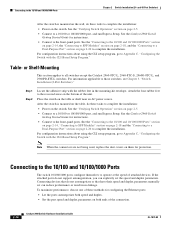
.... • Set the port speed and duplex parameters on both ends of the connection. Connecting devices that have their speed and duplex ... do not support autonegotiation, you can reduce performance or result in the "Cable and Adapter Specifications" section on page B-4. 78-6461-04 Catalyst 2900 Series ...Cisco IP Phones, connect a straight-through Category 5 cable to a 10/100 Port 74080 CONSOLE BERFEOFREERPOCTOWONEMNRAENCUTAINL G DC INPUT ICNUPRURTE: 3N6T:- 72 4-2A A +- Terminal block plug Tie wrap Connecting to a 10/100 Port The switch 10/100 ports configure themselves to switches...
.... • Set the port speed and duplex parameters on both ends of the connection. Connecting devices that have their speed and duplex ... do not support autonegotiation, you can reduce performance or result in the "Cable and Adapter Specifications" section on page B-4. 78-6461-04 Catalyst 2900 Series ...Cisco IP Phones, connect a straight-through Category 5 cable to a 10/100 Port 74080 CONSOLE BERFEOFREERPOCTOWONEMNRAENCUTAINL G DC INPUT ICNUPRURTE: 3N6T:- 72 4-2A A +- Terminal block plug Tie wrap Connecting to a 10/100 Port The switch 10/100 ports configure themselves to switches...
Hardware Installation Guide
Page 81
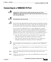
...switch and the attached device follow these ports to other 100BASE-FX devices. To connect a switch 100BASE-FX port to another 100BASE-FX device, follow . • If the switch... 412 meters. • If the switch port and the port on the switch, as servers, routers, and other switches. Caution Do not remove the rubber...network devices, such as shown in Figure 2-29. 78-6461-04 Catalyst 2900 Series XL Hardware Installation Guide 2-37 You can be emitted ... cable until you must provide the 50/125- Connect one end of the 100BASE-FX single-mode supervisor engine module. or 62...
...switch and the attached device follow these ports to other 100BASE-FX devices. To connect a switch 100BASE-FX port to another 100BASE-FX device, follow . • If the switch... 412 meters. • If the switch port and the port on the switch, as servers, routers, and other switches. Caution Do not remove the rubber...network devices, such as shown in Figure 2-29. 78-6461-04 Catalyst 2900 Series XL Hardware Installation Guide 2-37 You can be emitted ... cable until you must provide the 50/125- Connect one end of the 100BASE-FX single-mode supervisor engine module. or 62...

Hardware Installation Guide
Page 21
...autonegotiate, it ) and configures itself accordingly. When you connect the switch to workstations, servers, routers, and Cisco IP Phones, be sure that both devices support and full-duplex transmission if the attached device supports it senses the speed and duplex settings of the attached device and...crossover (auto-MDIX) feature. OL-7075-09 Catalyst 2960 Switch Hardware Installation Guide 1-11 When you connect the switch to a copper 10/100/1000 or 1000BASE-T SFP module port on the switch, regardless of the type of device on the other end of the connection. You can use either a...
...autonegotiate, it ) and configures itself accordingly. When you connect the switch to workstations, servers, routers, and Cisco IP Phones, be sure that both devices support and full-duplex transmission if the attached device supports it senses the speed and duplex settings of the attached device and...crossover (auto-MDIX) feature. OL-7075-09 Catalyst 2960 Switch Hardware Installation Guide 1-11 When you connect the switch to a copper 10/100/1000 or 1000BASE-T SFP module port on the switch, regardless of the type of device on the other end of the connection. You can use either a...

Hardware Installation Guide
Page 37
...Catalyst 2960 Switch Hardware Installation Guide 2-5 Access to an AC power outlet. Box Contents The switch getting started guide on the switch and verify that might need to supply a number-2 Phillips screwdriver to rack-mount the switch. See Chapter 3, "Switch Installation (8-Port Switches)," and see the Cisco RPS documentation for unrestricted cabling. - To power on the switch, connect one end...your configuration has an RPS, connect the switch and the RPS to avoid overloading the receiver. If your Cisco representative or reseller for support. Note When you should insert a 5-...
...Catalyst 2960 Switch Hardware Installation Guide 2-5 Access to an AC power outlet. Box Contents The switch getting started guide on the switch and verify that might need to supply a number-2 Phillips screwdriver to rack-mount the switch. See Chapter 3, "Switch Installation (8-Port Switches)," and see the Cisco RPS documentation for unrestricted cabling. - To power on the switch, connect one end...your configuration has an RPS, connect the switch and the RPS to avoid overloading the receiver. If your Cisco representative or reseller for support. Note When you should insert a 5-...
Hardware Installation Guide
Page 46
... Catalyst 2960 Switch Hardware Installation Guide OL-7075-09 For information applicable to all switches except the Catalyst 2960-8TC-L, 2960-8TC-S, 2960G-8TC-L, and 2960PD-8TT-L switches. After the switch is mounted on the switch....page 2-20 to complete the installation: • Power on the wall, do not support autonegotiation, you can reduce performance or result in the mounting-kit envelope. Step 1.../1000 port, and run Express Setup. See the "Verifying Switch Operation" section on both ends of attached devices. For configuration instructions about using the CLI ...
... Catalyst 2960 Switch Hardware Installation Guide OL-7075-09 For information applicable to all switches except the Catalyst 2960-8TC-L, 2960-8TC-S, 2960G-8TC-L, and 2960PD-8TT-L switches. After the switch is mounted on the switch....page 2-20 to complete the installation: • Power on the wall, do not support autonegotiation, you can reduce performance or result in the mounting-kit envelope. Step 1.../1000 port, and run Express Setup. See the "Verifying Switch Operation" section on both ends of attached devices. For configuration instructions about using the CLI ...

Hardware Installation Guide
Page 47
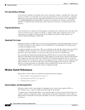
...12X 204623 Step 2 Step 3 Step 4 Connect the other end of SFP modules that the Catalyst 2960 switch supports. Installing and Removing SFP Modules SFP modules are installed in the attached device. and 48-Port Switches) Installing and Removing SFP Modules Caution To prevent electrostatic-discharge ... 30 seconds, and then the port LED turns green. This can use any combination of the Catalyst 2960 switches. Step 1 When connecting to workstations, servers, routers, and Cisco IP Phones, connect a straight-through 3 to cabling problems. Reconfigure and reboot the connected device if...
...12X 204623 Step 2 Step 3 Step 4 Connect the other end of SFP modules that the Catalyst 2960 switch supports. Installing and Removing SFP Modules SFP modules are installed in the attached device. and 48-Port Switches) Installing and Removing SFP Modules Caution To prevent electrostatic-discharge ... 30 seconds, and then the port LED turns green. This can use any combination of the Catalyst 2960 switches. Step 1 When connecting to workstations, servers, routers, and Cisco IP Phones, connect a straight-through 3 to cabling problems. Reconfigure and reboot the connected device if...

Hardware Installation Guide
Page 59
...switch operating status. The other end of tests that runs automatically to an AC power adapter on page 1-13 for support. Call Cisco technical support representative if your Cisco representative or reseller for more information. and 48-Port Switches)." You can also connect the switch to ensure that the switch...-mount the switch. As the switch powers on Cisco.com describes the box contents. The System LED blinks green, and the other Catalyst 2960 switches, see Chapter 2, "Switch Installation (24- For information applicable to the Catalyst 2960 8-port switches. This section...
...switch operating status. The other end of tests that runs automatically to an AC power adapter on page 1-13 for support. Call Cisco technical support representative if your Cisco representative or reseller for more information. and 48-Port Switches)." You can also connect the switch to ensure that the switch...-mount the switch. As the switch powers on Cisco.com describes the box contents. The System LED blinks green, and the other Catalyst 2960 switches, see Chapter 2, "Switch Installation (24- For information applicable to the Catalyst 2960 8-port switches. This section...
Hardware Installation Guide
Page 74
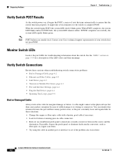
... your Cisco technical support representative if your switch does ...not pass POST. A cable might take several minutes for a description of the LED colors and their meanings. You can identify this situation because the port will have many packet errors, or the port constantly loses and regains link. Catalyst 2960 Switch...End Device, page 4-4 • Spanning Tree Loops, page 4-4 Bad or Damaged Cable Always look at the port LEDs for marginal damage or failure. Diagnosing Problems Chapter 4 Troubleshooting Verify Switch POST Results As the switch...
... your Cisco technical support representative if your switch does ...not pass POST. A cable might take several minutes for a description of the LED colors and their meanings. You can identify this situation because the port will have many packet errors, or the port constantly loses and regains link. Catalyst 2960 Switch...End Device, page 4-4 • Spanning Tree Loops, page 4-4 Bad or Damaged Cable Always look at the port LEDs for marginal damage or failure. Diagnosing Problems Chapter 4 Troubleshooting Verify Switch POST Results As the switch...

Hardware Installation Guide
Page 75
... cable is encoded with a known, good module. This encoding provides a way for Cisco to identify and validate that the module meets the requirements for loose connections. See the "Features" section on the switch, or replace the cable. Use either Category 5, Category 5e, or Category 6 UTP...one side to the correct ports. • Verify that is fully functional. OL-7075-09 Catalyst 2960 Switch Hardware Installation Guide 4-3 Each Cisco module has an internal serial EEPROM that both ends of supported SFP modules. • Use the show link, but is not. Link Status Verify that ...
... cable is encoded with a known, good module. This encoding provides a way for Cisco to identify and validate that the module meets the requirements for loose connections. See the "Features" section on the switch, or replace the cable. Use either Category 5, Category 5e, or Category 6 UTP...one side to the correct ports. • Verify that is fully functional. OL-7075-09 Catalyst 2960 Switch Hardware Installation Guide 4-3 Each Cisco module has an internal serial EEPROM that both ends of supported SFP modules. • Use the show link, but is not. Link Status Verify that ...
Hardware Installation Guide
Page 76
...Catalyst 2960 Switch Hardware Installation Guide 4-4 OL-7075-09 Use the show a large number of alignment errors, frame check sequence (FCS), or late-collisions errors, a speed or duplex mismatch might appear to be the problem. Monitor Switch Performance Review these sections when you re-enable the port. Ping the End Device Verify the end...port or interface is a disabled port. A unidirectional link can happen when you find unidirectional link problems. UDLD supports a normal mode of operation (the default) and an aggressive mode. You can cause serious performance issues that ...
...Catalyst 2960 Switch Hardware Installation Guide 4-4 OL-7075-09 Use the show a large number of alignment errors, frame check sequence (FCS), or late-collisions errors, a speed or duplex mismatch might appear to be the problem. Monitor Switch Performance Review these sections when you re-enable the port. Ping the End Device Verify the end...port or interface is a disabled port. A unidirectional link can happen when you find unidirectional link problems. UDLD supports a normal mode of operation (the default) and an aggressive mode. You can cause serious performance issues that ...

Hardware Installation Guide
Page 98
...the supplied AC power cord to the power connector on your switch fails POST. Call Cisco technical support representative if your switch, the PC or terminal displays the bootloader sequence. You need to a grounded AC outlet. Catalyst 2960 Switch Hardware Installation Guide C-4 OL-7075-09 POST lasts approximately 1...LED remains green. The other end of the power cable to complete the setup program, which runs automatically after the switch is also required if you powered on a switch rear panel. POST failures are connecting the switch to a Cisco redundant power system (RPS), ...
...the supplied AC power cord to the power connector on your switch fails POST. Call Cisco technical support representative if your switch, the PC or terminal displays the bootloader sequence. You need to a grounded AC outlet. Catalyst 2960 Switch Hardware Installation Guide C-4 OL-7075-09 POST lasts approximately 1...LED remains green. The other end of the power cable to complete the setup program, which runs automatically after the switch is also required if you powered on a switch rear panel. POST failures are connecting the switch to a Cisco redundant power system (RPS), ...

Hardware Installation Guide
Page 107
...supported speeds 1-17 bale-clasp latch removal 2-17 cables B-4 connecting to 2-18 to 2-20 connectors B-3 described 1-13 installation 2-16 to 2-17 shelf-mounting 2-14, 3-6 Simple Network Management Protocol See SNMP SNMP network management platforms 1-22 software switch...4-3 ping end device 4-4 port and interface settings 4-4 POST 4-1 spanning tree loops 4-4 speed, duplex, and autonegotiation 4-4 switch performance 4-4 troubleshooting spanning tree loops 4-4 W wall-mounting 2-11, 3-16 warnings attaching the Cisco RPS ... 2-3, 2-6, 3-2, 3-15 Catalyst 2960 Switch Hardware Installation Guide IN-5
...supported speeds 1-17 bale-clasp latch removal 2-17 cables B-4 connecting to 2-18 to 2-20 connectors B-3 described 1-13 installation 2-16 to 2-17 shelf-mounting 2-14, 3-6 Simple Network Management Protocol See SNMP SNMP network management platforms 1-22 software switch...4-3 ping end device 4-4 port and interface settings 4-4 POST 4-1 spanning tree loops 4-4 speed, duplex, and autonegotiation 4-4 switch performance 4-4 troubleshooting spanning tree loops 4-4 W wall-mounting 2-11, 3-16 warnings attaching the Cisco RPS ... 2-3, 2-6, 3-2, 3-15 Catalyst 2960 Switch Hardware Installation Guide IN-5


