

Hardware Installation Guide
Page 86
... terminal-emulation software to the switch: Step 1 Step 2 Configure your PC or terminal possible during the setup program. Connecting to a Module Port Chapter 2 Installation Connecting to a Module Port For information about installing and connecting to modules in the Catalyst 2924M XL and 2912MF XL ...(part number ACS-DSBUASYN=) containing that adapter from Cisco. Configure the baud rate and character format of the PC or terminal to match these steps to connect the PC or terminal to communicate with the switch through hardware flow control. The terminal-emulation software-...
... terminal-emulation software to the switch: Step 1 Step 2 Configure your PC or terminal possible during the setup program. Connecting to a Module Port Chapter 2 Installation Connecting to a Module Port For information about installing and connecting to modules in the Catalyst 2924M XL and 2912MF XL ...(part number ACS-DSBUASYN=) containing that adapter from Cisco. Configure the baud rate and character format of the PC or terminal to match these steps to connect the PC or terminal to communicate with the switch through hardware flow control. The terminal-emulation software-...
Hardware Installation Guide
Page 87
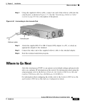
...settings and passwords after you configure IP information on page B-6 for the Catalyst 2900 Series XL and Catalyst 3500 Series XL Cisco IOS Release 12.0(5)WC(1). See the "Identifying a Rollover Cable" section on the switch. Where to Go Next Step 3 Using the supplied rollover cable, connect...Figure 2-31. Connect the other end of the pinout. For information about using the setup program, refer to the terminal. Start the terminal-emulation program. For information about configuring the switch, refer to the attached adapter. Figure 2-31 Connecting to the Console Port CONSOLE ...
...settings and passwords after you configure IP information on page B-6 for the Catalyst 2900 Series XL and Catalyst 3500 Series XL Cisco IOS Release 12.0(5)WC(1). See the "Identifying a Rollover Cable" section on the switch. Where to Go Next Step 3 Using the supplied rollover cable, connect...Figure 2-31. Connect the other end of the pinout. For information about using the setup program, refer to the terminal. Start the terminal-emulation program. For information about configuring the switch, refer to the attached adapter. Figure 2-31 Connecting to the Console Port CONSOLE ...

Hardware Installation Guide
Page 6
... Pinouts B-8 Configuring the Switch with the CLI-Based Setup Program C-1 Accessing the CLI C-1 Accessing the CLI Through Express Setup C-1 Accessing the CLI Through the Console Port C-2 Connecting to the Console Port C-3 Starting the Terminal Emulation Software C-3 Connecting to a Power Source C-4 Entering the Initial Configuration Information C-4 IP Settings C-5 Completing the Setup Program C-5 Catalyst 2960 Switch Hardware Installation Guide...
... Pinouts B-8 Configuring the Switch with the CLI-Based Setup Program C-1 Accessing the CLI C-1 Accessing the CLI Through Express Setup C-1 Accessing the CLI Through the Console Port C-2 Connecting to the Console Port C-3 Starting the Terminal Emulation Software C-3 Connecting to a Power Source C-4 Entering the Initial Configuration Information C-4 IP Settings C-5 Completing the Setup Program C-5 Catalyst 2960 Switch Hardware Installation Guide...
Hardware Installation Guide
Page 32
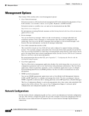
... use SNMP management applications such as HP OpenView or SunNet Manager. See the Catalyst 2960 Switch Command Reference on starting Network Assistant, see the device manager online help. • Cisco IOS command-line interface (CLI) The switch CLI is based on the switch. For setup instructions that are interconnected through a web browser. Management Options Chapter 1 Product Overview...
... use SNMP management applications such as HP OpenView or SunNet Manager. See the Catalyst 2960 Switch Command Reference on starting Network Assistant, see the device manager online help. • Cisco IOS command-line interface (CLI) The switch CLI is based on the switch. For setup instructions that are interconnected through a web browser. Management Options Chapter 1 Product Overview...
Hardware Installation Guide
Page 42
... Port" section on page 2-5. • Connect to complete the installation. See the Catalyst 2960 Switch Getting Started Guide for instructions. • Connect to Appendix C, "Configuring the Switch with the CLI-Based Setup Program." 2-10 Catalyst 2960 Switch Hardware Installation Guide OL-7075-09 Installing the Switch Chapter 2 Switch Installation (24- For configuration instructions about using the command-line interface (CLI...
... Port" section on page 2-5. • Connect to complete the installation. See the Catalyst 2960 Switch Getting Started Guide for instructions. • Connect to Appendix C, "Configuring the Switch with the CLI-Based Setup Program." 2-10 Catalyst 2960 Switch Hardware Installation Guide OL-7075-09 Installing the Switch Chapter 2 Switch Installation (24- For configuration instructions about using the command-line interface (CLI...
Hardware Installation Guide
Page 46
... four rubber feet to all switches except the Catalyst 2960-8TC-L, 2960-8TC-S, 2960G-8TC-L, and 2960PD-8TT-L switches. For configuration instructions about using the CLI setup program, go to the 10/100 and 10/100/1000 Ports Chapter 2 Switch Installation (24- For information applicable to Appendix C, "Configuring the Switch with the CLI-Based Setup Program." See the Catalyst 2960 Switch Getting Started Guide for...
... four rubber feet to all switches except the Catalyst 2960-8TC-L, 2960-8TC-S, 2960G-8TC-L, and 2960PD-8TT-L switches. For configuration instructions about using the CLI setup program, go to the 10/100 and 10/100/1000 Ports Chapter 2 Switch Installation (24- For information applicable to Appendix C, "Configuring the Switch with the CLI-Based Setup Program." See the Catalyst 2960 Switch Getting Started Guide for...

Hardware Installation Guide
Page 60
... Setup Program." After the switch is mounted on all sides by at least 3 inches (7.6 cm) of clearance around the ventilation openings to complete the installation. Connect to the Catalyst 2960 8-port switches. Catalyst 2960 Switch Hardware Installation Guide 3-6 OL-7075-09 Installing the Switch Chapter 3 Switch Installation (8-Port Switches) • Under the Desk- Power on top of clearance from each other Catalyst 2960 switches...
... Setup Program." After the switch is mounted on all sides by at least 3 inches (7.6 cm) of clearance around the ventilation openings to complete the installation. Connect to the Catalyst 2960 8-port switches. Catalyst 2960 Switch Hardware Installation Guide 3-6 OL-7075-09 Installing the Switch Chapter 3 Switch Installation (8-Port Switches) • Under the Desk- Power on top of clearance from each other Catalyst 2960 switches...
Hardware Installation Guide
Page 62
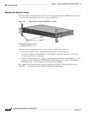
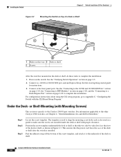
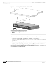
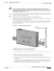
...section on page 3-5. 2. For configuration instructions about using the CLI setup program, go to the Catalyst 2960 8-port switches. or Shelf-Mounting (with Mounting Screws) This section is specific to Appendix C, "Configuring the Switch with proper clearance. The template is used to align the mounting...10/100 or 10/100/1000 port, and run Express Setup. and 48-Port Switches)." Peel the adhesive strip off the bottom of the screw template, and attach it to the other Catalyst 2960 switches, see Chapter 2, "Switch Installation (24- For information applicable to the underside of ...
...section on page 3-5. 2. For configuration instructions about using the CLI setup program, go to the Catalyst 2960 8-port switches. or Shelf-Mounting (with Mounting Screws) This section is specific to Appendix C, "Configuring the Switch with proper clearance. The template is used to align the mounting...10/100 or 10/100/1000 port, and run Express Setup. and 48-Port Switches)." Peel the adhesive strip off the bottom of the screw template, and attach it to the other Catalyst 2960 switches, see Chapter 2, "Switch Installation (24- For information applicable to the underside of ...
Hardware Installation Guide
Page 64
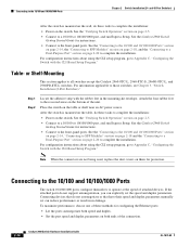
...page 2-20 to complete the installation: 1. See the "Verifying Switch Operation" section on the switch. See the switch getting started guide for instructions. 3. Connect to a 10/100 or 10/100/1000 port, and run Express Setup. Power on page 3-5. 2. Connect to the front-panel ...ports. For configuration instructions about using the CLI setup program, go to Appendix C, "Configuring the Switch with the CLI-Based Setup Program." 3-10 Catalyst 2960 Switch Hardware Installation Guide OL-7075-09
...page 2-20 to complete the installation: 1. See the "Verifying Switch Operation" section on the switch. See the switch getting started guide for instructions. 3. Connect to a 10/100 or 10/100/1000 port, and run Express Setup. Power on page 3-5. 2. Connect to the front-panel ...ports. For configuration instructions about using the CLI setup program, go to Appendix C, "Configuring the Switch with the CLI-Based Setup Program." 3-10 Catalyst 2960 Switch Hardware Installation Guide OL-7075-09
Hardware Installation Guide
Page 67
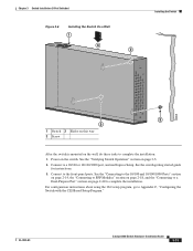
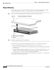
... front-panel ports. See the "Verifying Switch Operation" section on the switch. Connect to complete the installation: 1. See the switch getting started guide for instructions. 3. OL-7075-09 Catalyst 2960 Switch Hardware Installation Guide 3-13 For configuration instructions about using the CLI setup program, go to Appendix C, "Configuring the Switch with the CLI-Based Setup Program." Power on page 3-5. 2.
... front-panel ports. See the "Verifying Switch Operation" section on the switch. Connect to complete the installation: 1. See the switch getting started guide for instructions. 3. OL-7075-09 Catalyst 2960 Switch Hardware Installation Guide 3-13 For configuration instructions about using the CLI setup program, go to Appendix C, "Configuring the Switch with the CLI-Based Setup Program." Power on page 3-5. 2.
Hardware Installation Guide
Page 68
... OL-7075-09 Connect to a 10/100 or 10/100/1000 port, and run Express Setup. After the switch is specific to the Catalyst 2960 8-port switches. See the "Verifying Switch Operation" section on a metal surface. Installing the Switch Chapter 3 Switch Installation (8-Port Switches) Magnet Mounting This section is attached to the mounting magnet, do these tasks to complete...
... OL-7075-09 Connect to a 10/100 or 10/100/1000 port, and run Express Setup. After the switch is specific to the Catalyst 2960 8-port switches. See the "Verifying Switch Operation" section on a metal surface. Installing the Switch Chapter 3 Switch Installation (8-Port Switches) Magnet Mounting This section is attached to the mounting magnet, do these tasks to complete...
Hardware Installation Guide
Page 70
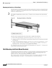
... Figure 3-9. You can order a kit containing the 19-inch rack-mounting brackets and hardware from Cisco. and 48-Port Switches)." 3-16 Catalyst 2960 Switch Hardware Installation Guide OL-7075-09 Use either the 10-32 pan-head screws or the 12-...Setup Program." Figure 3-9 Mounting the Switch in a 19-Inch Rack SYST STAT DPLX SPD MODE CONSOLE 1x 2x 3x 4x 5x 6x 7x 8x 1 Catalyst 2960 Series 1 204638 1 Phillips machine screws After the switch is specific to the other Catalyst 2960 switches, see Chapter 2, "Switch Installation (24- Connect to the switch, insert the switch...
... Figure 3-9. You can order a kit containing the 19-inch rack-mounting brackets and hardware from Cisco. and 48-Port Switches)." 3-16 Catalyst 2960 Switch Hardware Installation Guide OL-7075-09 Use either the 10-32 pan-head screws or the 12-...Setup Program." Figure 3-9 Mounting the Switch in a 19-Inch Rack SYST STAT DPLX SPD MODE CONSOLE 1x 2x 3x 4x 5x 6x 7x 8x 1 Catalyst 2960 Series 1 204638 1 Phillips machine screws After the switch is specific to the other Catalyst 2960 switches, see Chapter 2, "Switch Installation (24- Connect to the switch, insert the switch...
Hardware Installation Guide
Page 71
... provide easier access to a 10/100 or 10/100/1000 port, and run Express Setup. Connect to the cables. See the switch getting started guide for instructions. 3. OL-7075-09 Catalyst 2960 Switch Hardware Installation Guide 3-17 Follow the same steps to attach the second bracket to safety ...regulations. Mount the switch with its front panel facing up or sideways according to the opposite side, as shown in a hazardous ...
... provide easier access to a 10/100 or 10/100/1000 port, and run Express Setup. Connect to the cables. See the switch getting started guide for instructions. 3. OL-7075-09 Catalyst 2960 Switch Hardware Installation Guide 3-17 Follow the same steps to attach the second bracket to safety ...regulations. Mount the switch with its front panel facing up or sideways according to the opposite side, as shown in a hazardous ...
Hardware Installation Guide
Page 72
...; Start the device manager, which is in the switch memory, to manage individual and standalone switches. See the Catalyst 2960 Switch Software Configuration Guide and the Catalyst 2960 Switch Command Reference on Cisco.com for information on using the CLI setup program, go to Appendix C, "Configuring the Switch with the CLI-Based Setup Program." Through this GUI, you can configure and monitor...
...; Start the device manager, which is in the switch memory, to manage individual and standalone switches. See the Catalyst 2960 Switch Software Configuration Guide and the Catalyst 2960 Switch Command Reference on Cisco.com for information on using the CLI setup program, go to Appendix C, "Configuring the Switch with the CLI-Based Setup Program." Through this GUI, you can configure and monitor...
Hardware Installation Guide
Page 77
..., the LEDs above the mode button turn green. Continue holding down the Mode button. OL-7075-09 Catalyst 2960 Switch Hardware Installation Guide 4-5 To maximize switch performance and to ensure a link, follow this step and run Express Setup to manually set both ends of the connection. for the ports on both sides of the connection...
..., the LEDs above the mode button turn green. Continue holding down the Mode button. OL-7075-09 Catalyst 2960 Switch Hardware Installation Guide 4-5 To maximize switch performance and to ensure a link, follow this step and run Express Setup to manually set both ends of the connection. for the ports on both sides of the connection...

Hardware Installation Guide
Page 78
... serial number of your switch. You can configure the switch by using Express Setup as described in Appendix C, "Configuring the Switch with the switch. Figure 4-1 Serial Number Location on the Catalyst 2960-24PC-L, 2960-24LT-L, 2960-48PST-L, 2960-24TC-S, 2960-48TC-S, 2960-24TT-L, 2960-48TT-S, 2960-48TT-L, 2960G-24TC-L, 2960-24PC-S, 2960-24LC-S, 2960-48PST-S, and 2960G-48TC-L Switches 140035, 0781-00374-01 SN: XXXNNNNXXXX Cisco 11-character label...
... serial number of your switch. You can configure the switch by using Express Setup as described in Appendix C, "Configuring the Switch with the switch. Figure 4-1 Serial Number Location on the Catalyst 2960-24PC-L, 2960-24LT-L, 2960-48PST-L, 2960-24TC-S, 2960-48TC-S, 2960-24TT-L, 2960-48TT-S, 2960-48TT-L, 2960G-24TC-L, 2960-24PC-S, 2960-24LC-S, 2960-48PST-S, and 2960G-48TC-L Switches 140035, 0781-00374-01 SN: XXXNNNNXXXX Cisco 11-character label...
Hardware Installation Guide
Page 95
... the CLI: • Entering the Initial Configuration Information, page C-4 • Completing the Setup Program, page C-5 OL-7075-09 Catalyst 2960 Switch Hardware Installation Guide C-1 Before you can access the CLI on the switch and using Express Setup. Accessing the CLI, page C-1 2. C A P P E N D I X Configuring the Switch with the CLI-Based Setup Program This appendix provides a command-line interface (CLI)-based...
... the CLI: • Entering the Initial Configuration Information, page C-4 • Completing the Setup Program, page C-5 OL-7075-09 Catalyst 2960 Switch Hardware Installation Guide C-1 Before you can access the CLI on the switch and using Express Setup. Accessing the CLI, page C-1 2. C A P P E N D I X Configuring the Switch with the CLI-Based Setup Program This appendix provides a command-line interface (CLI)-based...
Hardware Installation Guide
Page 96
... using the write memory privileged EXEC command. Catalyst 2960 Switch Hardware Installation Guide C-2 OL-7075-09 For configuration information for this feature, see the switch software configuration guide or the switch command reference. Note While in Express Setup mode, the IP address 10.0.0.1 remains active on a configured or unconfigured switch by connecting the console port of what...
... using the write memory privileged EXEC command. Catalyst 2960 Switch Hardware Installation Guide C-2 OL-7075-09 For configuration information for this feature, see the switch software configuration guide or the switch command reference. Note While in Express Setup mode, the IP address 10.0.0.1 remains active on a configured or unconfigured switch by connecting the console port of what...
Hardware Installation Guide
Page 97
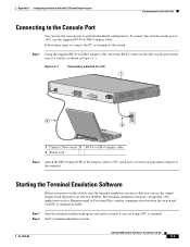
... a session if you can use the supplied RJ-45-to-DB-9 adapter cable. Appendix C Configuring the Switch with the CLI-Based Setup Program Connecting to the Console Port Connecting to the Console Port You can see the output display from the ... are using a PC or terminal. Figure C-1 Connecting a Switch to a PC 1 CONSOLE 137088 3 2 1 Catalyst 2960 switch 3 RJ-45-to perform the initial configuration. Step 2 Start a terminal-emulation session. OL-7075-09 Catalyst 2960 Switch Hardware Installation Guide C-3 To connect the switch console port to a PC, use the console port to...
... a session if you can use the supplied RJ-45-to-DB-9 adapter cable. Appendix C Configuring the Switch with the CLI-Based Setup Program Connecting to the Console Port Connecting to the Console Port You can see the output display from the ... are using a PC or terminal. Figure C-1 Connecting a Switch to a PC 1 CONSOLE 137088 3 2 1 Catalyst 2960 switch 3 RJ-45-to perform the initial configuration. Step 2 Start a terminal-emulation session. OL-7075-09 Catalyst 2960 Switch Hardware Installation Guide C-3 To connect the switch console port to a PC, use the console port to...

Hardware Installation Guide
Page 98
...RPS. When the POST completes successfully, the System LED remains green. POST failures are connecting the switch to a Cisco redundant power system (RPS), refer to the documentation that the switch functions properly. See Figure C-1. POST lasts approximately 1 minute. The System LED blinks green, ... supplied AC power cord to the power connector on your switch fails POST. Catalyst 2960 Switch Hardware Installation Guide C-4 OL-7075-09 The RPS LED remains green for the switch to communicate with the CLI-Based Setup Program Step 3 Configure the baud rate and character format of...
...RPS. When the POST completes successfully, the System LED remains green. POST failures are connecting the switch to a Cisco redundant power system (RPS), refer to the documentation that the switch functions properly. See Figure C-1. POST lasts approximately 1 minute. The System LED blinks green, ... supplied AC power cord to the power connector on your switch fails POST. Catalyst 2960 Switch Hardware Installation Guide C-4 OL-7075-09 The RPS LED remains green for the switch to communicate with the CLI-Based Setup Program Step 3 Configure the baud rate and character format of...