Getting Started Guide
Page 2
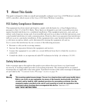
... and, if not installed and used in accordance with electrical circuitry and be determined by one or more of the Cisco 2500 Series Wireless Controllers. Before you install and minimally configure your Cisco 2504 Wireless Controller (2504 controller), which the receiver is connected. • Consult the dealer or an experienced radio/TV technician...
... and, if not installed and used in accordance with electrical circuitry and be determined by one or more of the Cisco 2500 Series Wireless Controllers. Before you install and minimally configure your Cisco 2504 Wireless Controller (2504 controller), which the receiver is connected. • Consult the dealer or an experienced radio/TV technician...
Getting Started Guide
Page 5
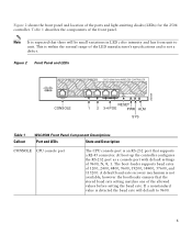
... from unit to 9600. 5 Note It is an RS-232 port that there will default to unit. Figure 2 Front Panel and LEDs 282249 CONSOLE CONSOLE CISCO 2500 Series WIRELESS CONTROLLER RESET Model 2504 1 2 3 4 PWR SYS ALM RESET 1 2 3-4 POE PWR ALM SYS Table 1 Callout WLC2504 Front Panel Component ... rate setting matches one of the front panel. Figure 2 shows the front panel and location of 9600, N, 8, 1. At boot-up the controller configures the RS-232 port as a console port with default settings of the ports and light-emitting diodes (LEDs) for the 2504 controller.
... from unit to 9600. 5 Note It is an RS-232 port that there will default to unit. Figure 2 Front Panel and LEDs 282249 CONSOLE CONSOLE CISCO 2500 Series WIRELESS CONTROLLER RESET Model 2504 1 2 3 4 PWR SYS ALM RESET 1 2 3-4 POE PWR ALM SYS Table 1 Callout WLC2504 Front Panel Component ... rate setting matches one of the front panel. Figure 2 shows the front panel and location of 9600, N, 8, 1. At boot-up the controller configures the RS-232 port as a console port with default settings of the ports and light-emitting diodes (LEDs) for the 2504 controller.

Getting Started Guide
Page 6
...-switch connection using multiple an AP-Manager or data interface. 6 This port is designed so that 1500 VAC rms isolation (per the 802.3 specification) is configured to these ports. The ports can do not connect access point devices to I2C address 0x40/41 (0100 000r/w). Callout Port and LEDs State and...
...-switch connection using multiple an AP-Manager or data interface. 6 This port is designed so that 1500 VAC rms isolation (per the 802.3 specification) is configured to these ports. The ports can do not connect access point devices to I2C address 0x40/41 (0100 000r/w). Callout Port and LEDs State and...
Getting Started Guide
Page 9
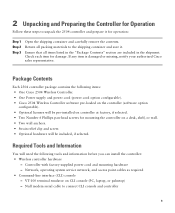
... container and carefully remove the contents. Package Contents Each 2504 controller package contains the following items: • One Cisco 2504 Wireless Controller. • One Power supply and power cord (power cord option configurable). • Cisco 2504 Wireless Controller software pre-loaded on CLI console (PC, laptop, or palmtop) - Null modem serial cable to...
... container and carefully remove the contents. Package Contents Each 2504 controller package contains the following items: • One Cisco 2504 Wireless Controller. • One Power supply and power cord (power cord option configurable). • Cisco 2504 Wireless Controller software pre-loaded on CLI console (PC, laptop, or palmtop) - Null modem serial cable to...

Getting Started Guide
Page 10
...• DHCP bridging • Whether or not to 19 printable ASCII characters. • An 802.11 network name (SSID), such as controller. Cisco uses an integral TFTP server. The system name can contain up to 24 printable ASCII characters. • Local TFTP server (required for an untagged ... that third-party TFTP servers cannot run on the same workstation as rfgrp40 if required. Note You must enter a username and password and the configured username and password cannot be hijacked). - This means that will supply IP addresses to a VLAN, such as 40 or 0 for downloading operating...
...• DHCP bridging • Whether or not to 19 printable ASCII characters. • An 802.11 network name (SSID), such as controller. Cisco uses an integral TFTP server. The system name can contain up to 24 printable ASCII characters. • Local TFTP server (required for an untagged ... that third-party TFTP servers cannot run on the same workstation as rfgrp40 if required. Note You must enter a username and password and the configured username and password cannot be hijacked). - This means that will supply IP addresses to a VLAN, such as 40 or 0 for downloading operating...

Getting Started Guide
Page 11
...of the 802.11a, 802.11b, 802.11g, or 802.11n networks, either enabled or disabled. • Status of equipment connected to the Cisco Wireless LAN Controller Configuration Guide for this installation. This guide is not obstructed. Enter help to see a list or refer to the 10/100/1000 Mb/s Ethernet ports...the controller is available at least 4 in a secure equipment room or wiring closet. • RADIUS server IP address, communications port, and secret if you are configuring a RADIUS server, such as 10.40.0.3, 1812, and mysecretcode. • The country code for country code information.
...of the 802.11a, 802.11b, 802.11g, or 802.11n networks, either enabled or disabled. • Status of equipment connected to the Cisco Wireless LAN Controller Configuration Guide for this installation. This guide is not obstructed. Enter help to see a list or refer to the 10/100/1000 Mb/s Ethernet ports...the controller is available at least 4 in a secure equipment room or wiring closet. • RADIUS server IP address, communications port, and secret if you are configuring a RADIUS server, such as 10.40.0.3, 1812, and mysecretcode. • The country code for country code information.

Getting Started Guide
Page 13
Mounting the Controller on a Wall (Rack-Mount Brackets) The controller can order a kit with 19-inch rack mounting brackets and hardware from Cisco. Failure to use the correct hardware or to follow these steps: Step 1 Attach the 19-inch brackets to each side of space ...mounted on a wall using rack-mount brackets, follow the correct procedures could result in a hazardous situation to people and damage to the Network For configuration instructions about using an optional rack-mount bracket kit that is not included with #10-32 flat head screws provided in Figure 5 with the controller...
Mounting the Controller on a Wall (Rack-Mount Brackets) The controller can order a kit with 19-inch rack mounting brackets and hardware from Cisco. Failure to use the correct hardware or to follow these steps: Step 1 Attach the 19-inch brackets to each side of space ...mounted on a wall using rack-mount brackets, follow the correct procedures could result in a hazardous situation to people and damage to the Network For configuration instructions about using an optional rack-mount bracket kit that is not included with #10-32 flat head screws provided in Figure 5 with the controller...

Getting Started Guide
Page 15
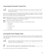
... the following tasks to complete the installation: • Connecting the Controller Console Port • Securing the Power Adapter Cable • Connecting to the Network For configuration instructions about using the CLI setup program, see the "Running the Bootup Script and Power-On Self Test" section on the Wall 282085 1 2 3 1 Front panel...
... the following tasks to complete the installation: • Connecting the Controller Console Port • Securing the Power Adapter Cable • Connecting to the Network For configuration instructions about using the CLI setup program, see the "Running the Bootup Script and Power-On Self Test" section on the Wall 282085 1 2 3 1 Front panel...
Getting Started Guide
Page 18
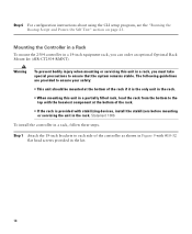
... flat head screws provided in the kit. 18 Mounting the Controller in a Rack To mount the 2504 controller in a rack, follow these steps. Step 6 For configuration instructions about using the CLI setup program, see the "Running the Bootup Script and Power-On Self Test" section on page 23. The following guidelines...
... flat head screws provided in the kit. 18 Mounting the Controller in a Rack To mount the 2504 controller in a rack, follow these steps. Step 6 For configuration instructions about using the CLI setup program, see the "Running the Bootup Script and Power-On Self Test" section on page 23. The following guidelines...

Getting Started Guide
Page 20
Figure 10 Mounting the Controller in a 19-Inch Rack 1 282086 1 #10-32 pan-head screws or #12-24 slotted head screws Step 3 Step 4 After the controller is mounted in the rack, perform the following tasks to complete the installation: • Connecting the Controller Console Port • Securing the Power Adapter Cable • Connecting to the Network For configuration instructions about using the CLI setup program, see the "Running the Bootup Script and Power-On Self Test" section on page 23. 20
Figure 10 Mounting the Controller in a 19-Inch Rack 1 282086 1 #10-32 pan-head screws or #12-24 slotted head screws Step 3 Step 4 After the controller is mounted in the rack, perform the following tasks to complete the installation: • Connecting the Controller Console Port • Securing the Power Adapter Cable • Connecting to the Network For configuration instructions about using the CLI setup program, see the "Running the Bootup Script and Power-On Self Test" section on page 23. 20
Getting Started Guide
Page 21
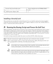
... at the plug pins. To connect the PC to a PC that uses a VT-100 terminal emulator (such as HyperTerminal, ProComm, Minicom, or Tip). Configure the terminal emulation program for basic operations, you can be damaged if the power cable is pulled or if the power adapter falls. Note The... Cisco 2106 power adapter is not installed, the power connector can configure the 2504 controller for the following parameters: • 9600 baud • 8 data bits • No flow control • 1 ...
... at the plug pins. To connect the PC to a PC that uses a VT-100 terminal emulator (such as HyperTerminal, ProComm, Minicom, or Tip). Configure the terminal emulation program for basic operations, you can be damaged if the power cable is pulled or if the power adapter falls. Note The... Cisco 2106 power adapter is not installed, the power connector can configure the 2504 controller for the following parameters: • 9600 baud • 8 data bits • No flow control • 1 ...
Getting Started Guide
Page 23
... the back panel. Before performing this test, you plug the controller into an AC power source, the bootup script initializes the system, verifies the hardware configuration, loads its microcode into a grounded 100 to run the bootup script and conduct the power-on self test (POST), follow these steps: Step 1 Step ...does not light, make sure that the power connections to secure the controller. The Bootloader Options menu appears. Security clip secured with its stored configurations. To run a previous release of the controller code, press Esc when the boot loader prompt appears.
... the back panel. Before performing this test, you plug the controller into an AC power source, the bootup script initializes the system, verifies the hardware configuration, loads its microcode into a grounded 100 to run the bootup script and conduct the power-on self test (POST), follow these steps: Step 1 Step ...does not light, make sure that the power connections to secure the controller. The Bootloader Options menu appears. Security clip secured with its stored configurations. To run a previous release of the controller code, press Esc when the boot loader prompt appears.
Getting Started Guide
Page 24
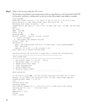
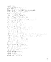
...minutes. Continue booting the controller or press Esc to access the following bootup display example: CISCO SYSTEMS WLCNG Boot Loader Version 1.0.15 (Built on Nov 23 2010 at 07:51:36 by cisco) Board Revision 0.0 (SN: PSJ143302MT, Type: AIR-CT2504-K9) (P) Verifying boot ...rate) CPU Cores: 4 DRAM: 1024 MB Flash: 32 MB Clearing DRAM........ Environment MAC address override CF Bus 0 (IDE): OK IDE device 0: - Clear configuration 5. Active interface E - Type: Hard Disk - Active 2. Model: 1GB CompactFlash Card Firm: CF B612J Ser#: C181101244A1Yb3A5QNU - Change active boot image 4. Loading ...
...minutes. Continue booting the controller or press Esc to access the following bootup display example: CISCO SYSTEMS WLCNG Boot Loader Version 1.0.15 (Built on Nov 23 2010 at 07:51:36 by cisco) Board Revision 0.0 (SN: PSJ143302MT, Type: AIR-CT2504-K9) (P) Verifying boot ...rate) CPU Cores: 4 DRAM: 1024 MB Flash: 32 MB Clearing DRAM........ Environment MAC address override CF Bus 0 (IDE): OK IDE device 0: - Clear configuration 5. Active interface E - Type: Hard Disk - Active 2. Model: 1GB CompactFlash Card Firm: CF B612J Ser#: C181101244A1Yb3A5QNU - Change active boot image 4. Loading ...
Getting Started Guide
Page 25
...usr/bin/gettyOrMwar' Cryptographic library self-test....passed! Software Copyright Cisco Systems, Inc. Flags-[DUTY CYCLE] : ok Fastpath CPU00: Initializing last packet received queue. XML config selected Validating XML configuration octeon_device_init: found 1 DPs /dev/fpga: No such device ...or address readCPUConfigData: cardid 0x6060001 Cisco is a trademark of cores(2) Fastpath CPU00: Init MBUF size: 1856, Subsequent MBUF...
...usr/bin/gettyOrMwar' Cryptographic library self-test....passed! Software Copyright Cisco Systems, Inc. Flags-[DUTY CYCLE] : ok Fastpath CPU00: Initializing last packet received queue. XML config selected Validating XML configuration octeon_device_init: found 1 DPs /dev/fpga: No such device ...or address readCPUConfigData: cardid 0x6060001 Cisco is a trademark of cores(2) Fastpath CPU00: Init MBUF size: 1856, Subsequent MBUF...
Getting Started Guide
Page 27
Change active boot image 4. Format FLASH Drive 6. XML config selected Validating XML configuration octeon_device_init: found 1 DPs /dev/fpga: No such device or address readCPUConfigData: cardid 0x6060001 Cisco is a trademark of Cisco Systems, Inc. All rights reserved. Step 5 Continue booting the controller or press ... type = block dump-device = 254:4 disrupt level = header compress = none ifconfig: SIOCGIFFLAGS: No such device Detecting Hardware ... Clear configuration 5. init started: BusyBox v1.6.0 (2010-05-13 17:50:10 EDT) multi-call binary starting pid 805, tty '/dev/ttyS0': '/...
Change active boot image 4. Format FLASH Drive 6. XML config selected Validating XML configuration octeon_device_init: found 1 DPs /dev/fpga: No such device or address readCPUConfigData: cardid 0x6060001 Cisco is a trademark of Cisco Systems, Inc. All rights reserved. Step 5 Continue booting the controller or press ... type = block dump-device = 254:4 disrupt level = header compress = none ifconfig: SIOCGIFFLAGS: No such device Detecting Hardware ... Clear configuration 5. init started: BusyBox v1.6.0 (2010-05-13 17:50:10 EDT) multi-call binary starting pid 805, tty '/dev/ttyS0': '/...

Getting Started Guide
Page 29
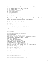
... System Name [Cisco_d9:16:24]: Note The startup wizard runs the first time that you can use to configure your controller for basic operation. Welcome to the Cisco Wizard Configuration Tool Use the '-' character to the wizard prompt. 29 The second time you power it on page 9.... If you for basic configuration information. Using the Startup Wizard Before you can use the startup wizard, you for a login ID...
... System Name [Cisco_d9:16:24]: Note The startup wizard runs the first time that you can use to configure your controller for basic operation. Welcome to the Cisco Wizard Configuration Tool Use the '-' character to the wizard prompt. 29 The second time you power it on page 9.... If you for basic configuration information. Using the Startup Wizard Before you can use the startup wizard, you for a login ID...
Getting Started Guide
Page 30
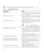
... each . Enter the IP address of the default router. Enter the IP address of the management interface. Ports values are 1 to match the switch interface configuration. Table 3 Startup Wizard Information Wizard Setting System Name Administrative user name Administrative password Action Enter the system name, which is no default administrative password, you...
... each . Enter the IP address of the default router. Enter the IP address of the management interface. Ports values are 1 to match the switch interface configuration. Table 3 Startup Wizard Information Wizard Setting System Name Administrative user name Administrative password Action Enter the system name, which is no default administrative password, you...
Getting Started Guide
Page 31
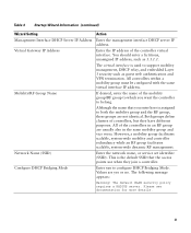
... Name If desired, enter the name of the controllers in an RF group are not identical. This is used to configure DHCP Bridging Mode. Configure DHCP Bridging Mode Enter yes to support mobility management, DHCP relay, and embedded Layer 3 security such as 1.1.1.1. However,...web authentication and VPN termination. Both groups define clusters of the controller virtual interface. All controllers within a mobility group must be configured with the same virtual interface IP address. The default WLAN security policy requires a RADIUS server. Table 3 Startup Wizard Information (continued...
... Name If desired, enter the name of the controllers in an RF group are not identical. This is used to configure DHCP Bridging Mode. Configure DHCP Bridging Mode Enter yes to support mobility management, DHCP relay, and embedded Layer 3 security such as 1.1.1.1. However,...web authentication and VPN termination. Both groups define clusters of the controller virtual interface. All controllers within a mobility group must be configured with the same virtual interface IP address. The default WLAN security policy requires a RADIUS server. Table 3 Startup Wizard Information (continued...
Getting Started Guide
Page 32
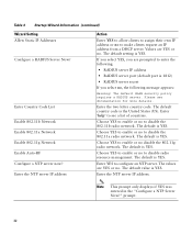
... YES to enable or no , the following message appears: Warning! The default is YES. Table 3 Startup Wizard Information (continued) Wizard Setting Allow Static IP Addresses Configure a RADIUS Server Now? Enter Country Code List Enable 802.11b Network Enable 802.11a Network Enable 802.11g Network Enable Auto-RF... server now? Enter the NTP server IP address Action Enter YES to allow clients to assign their own IP address or no to configure an NTP server. Please see a list of countries. Choose YES to enable or no to disable the 802.11b radio network. The default is YES. ...
... YES to enable or no , the following message appears: Warning! The default is YES. Table 3 Startup Wizard Information (continued) Wizard Setting Allow Static IP Addresses Configure a RADIUS Server Now? Enter Country Code List Enable 802.11b Network Enable 802.11a Network Enable 802.11g Network Enable Auto-RF... server now? Enter the NTP server IP address Action Enter YES to allow clients to assign their own IP address or no to configure an NTP server. Please see a list of countries. Choose YES to enable or no to disable the 802.11b radio network. The default is YES. ...
Getting Started Guide
Page 33
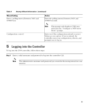
... and prompts you created in the startup wizard are yes and no. prompt. Values are case sensitive. 33 Enter yes if the configuration entered is entered. Note This prompt only displays if YES was entered in . 5 Logging into the Controller To log into the ... password you to log into the 2504 controller, follow these steps: Step 1 Enter a valid username and password to log in the "Configure a NTP Server Now?" Configuration correct? If yes is correct. Table 3 Startup Wizard Information (continued) Wizard Setting Enter a polling interval between 3600 and 604800 secs Action...
... and prompts you created in the startup wizard are yes and no. prompt. Values are case sensitive. 33 Enter yes if the configuration entered is entered. Note This prompt only displays if YES was entered in . 5 Logging into the Controller To log into the ... password you to log into the 2504 controller, follow these steps: Step 1 Enter a valid username and password to log in the "Configure a NTP Server Now?" Configuration correct? If yes is correct. Table 3 Startup Wizard Information (continued) Wizard Setting Enter a polling interval between 3600 and 604800 secs Action...

