
Service Manual
Page 3
... specifications, names of operation used for the machine's pickup/feeding system. Chapter 4 Image Formation System discusses the principles of parts, and how originals are reproduced. It also explains the timing at which image formation-related mechanisms are operated, and shows ... provides tables of operation used for the site of periodically replaced parts and consumables/durables and scheduled servicing charts. Appendix contains a general timing chart and general circuit diagrams. COPYRIGHT © 1999 CANON INC. It also shows how the unit may be disassembled...
... specifications, names of operation used for the machine's pickup/feeding system. Chapter 4 Image Formation System discusses the principles of parts, and how originals are reproduced. It also explains the timing at which image formation-related mechanisms are operated, and shows ... provides tables of operation used for the site of periodically replaced parts and consumables/durables and scheduled servicing charts. Appendix contains a general timing chart and general circuit diagrams. COPYRIGHT © 1999 CANON INC. It also shows how the unit may be disassembled...
Service Manual
Page 9
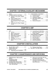
... 8-17 II. DISASSEMBLY/ASSEMBLY ..... 8-18 A. Electrical System 8-33 CHAPTER 9 INSTALLATION I . SELECTING A SITE 9-1 II. CANON PC800s/900s REV.0 AUG. 1999 PRINTED IN JAPAN (IMPRIME AU JAPON) vii Copyboard Glass 7-16 D. Removing the ADF 8-19...MECHANISMS I . FANS 7-1 II. DISASSEMBLY/ASSEMBLY ........7-7 A. Pickup Operation 8-8 F. PERIODICALLY REPLACED PARTS 10-1 II. Storing the Cartridge with the Packaging Seal Removed 10-3 COPYRIGHT © 1999 CANON INC. Outline 8-1 B Basic Construction 8-2 C. Detecting an Original 8-6 E. Controlling the...
... 8-17 II. DISASSEMBLY/ASSEMBLY ..... 8-18 A. Electrical System 8-33 CHAPTER 9 INSTALLATION I . SELECTING A SITE 9-1 II. CANON PC800s/900s REV.0 AUG. 1999 PRINTED IN JAPAN (IMPRIME AU JAPON) vii Copyboard Glass 7-16 D. Removing the ADF 8-19...MECHANISMS I . FANS 7-1 II. DISASSEMBLY/ASSEMBLY ........7-7 A. Pickup Operation 8-8 F. PERIODICALLY REPLACED PARTS 10-1 II. Storing the Cartridge with the Packaging Seal Removed 10-3 COPYRIGHT © 1999 CANON INC. Outline 8-1 B Basic Construction 8-2 C. Detecting an Original 8-6 E. Controlling the...
Service Manual
Page 257
SCHEDULED SERVICING ....... 10-1 IV. DURABLES AND CONSUMABLES 10-1 III. Storing the Cartridge with the Packaging Seal Removed 10-3 COPYRIGHT © 1999 CANON INC. STORING AND HANDLING THE CARTRIDGE 10-2 A. PERIODICALLY REPLACED PARTS 10-1 II. CANON PC800s/900s REV.0 AUG. 1999 PRINTED IN JAPAN (IMPRIME AU JAPON) Storing and Handling the Cartridge with the Packaging Seal Intact ........ 10-2 B. CHAPTER 10 MAINTENANCE AND SERVICING I.
SCHEDULED SERVICING ....... 10-1 IV. DURABLES AND CONSUMABLES 10-1 III. Storing the Cartridge with the Packaging Seal Removed 10-3 COPYRIGHT © 1999 CANON INC. STORING AND HANDLING THE CARTRIDGE 10-2 A. PERIODICALLY REPLACED PARTS 10-1 II. CANON PC800s/900s REV.0 AUG. 1999 PRINTED IN JAPAN (IMPRIME AU JAPON) Storing and Handling the Cartridge with the Packaging Seal Intact ........ 10-2 B. CHAPTER 10 MAINTENANCE AND SERVICING I.
Service Manual
Page 258
III. SCHEDULED SERVICING The machine does not have parts which require scheduled servicing. CHAPTER 10 MAINTENANCE AND SERVICING I. II. COPYRIGHT © 1999 CANON INC. CANON PC800s/900s REV.0 AUG. 1999 PRINTED IN JAPAN (IMPRIME AU JAPON) 10-1 PERIODICALLY REPLACED PARTS The machine does not have any parts which must be replaced on a periodical basis. DURABLES AND CONSUMABLES The machine does not have items designated as durables or consumables.
III. SCHEDULED SERVICING The machine does not have parts which require scheduled servicing. CHAPTER 10 MAINTENANCE AND SERVICING I. II. COPYRIGHT © 1999 CANON INC. CANON PC800s/900s REV.0 AUG. 1999 PRINTED IN JAPAN (IMPRIME AU JAPON) 10-1 PERIODICALLY REPLACED PARTS The machine does not have any parts which must be replaced on a periodical basis. DURABLES AND CONSUMABLES The machine does not have items designated as durables or consumables.
Service Manual
Page 306
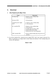
After Replacing the Major Parts Parts Scanning lamp AE sensor PCB Composite power supply PCB*1 DC controller PCB ADF controller PCB Adjustment 1. AE mechanism) 1. AE mechanism 3. Reproduction ratio (fine adjustment) 1. if (... power supply PCB, check copy images using the Test Sheet; Image leading edge margin 5. Table 11-206 COPYRIGHT © 1999 CANON INC. Electrical 1. Intensity of the scanning lamp and execute AE adjustment. CANON PC800s/900s REV.0 AUG. 1999 PRINTED IN JAPAN (IMPRIME AU JAPON) 11-41 AE mechanism (1. Leading edge non-image...
After Replacing the Major Parts Parts Scanning lamp AE sensor PCB Composite power supply PCB*1 DC controller PCB ADF controller PCB Adjustment 1. AE mechanism) 1. AE mechanism 3. Reproduction ratio (fine adjustment) 1. if (... power supply PCB, check copy images using the Test Sheet; Image leading edge margin 5. Table 11-206 COPYRIGHT © 1999 CANON INC. Electrical 1. Intensity of the scanning lamp and execute AE adjustment. CANON PC800s/900s REV.0 AUG. 1999 PRINTED IN JAPAN (IMPRIME AU JAPON) 11-41 AE mechanism (1. Leading edge non-image...
Service Manual
Page 318
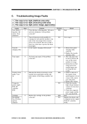
...plate and the side plate (metal) of storage. 2. Replace the varistor. 1. Check the composite power supply and the DC controller PCB. CANON PC800s/900s REV.0 AUG. 1999 PRINTED IN JAPAN (...high-voltage terminal contacts for electrical continuity. 2. Is the problem corrected? Replace the transfer charging roller. 1. End. Replace the cartridge. YES/NO YES NO NO YES YES NO YES NO ...the electrical resistance on the correct method of the fixing assembly. Is it 0Ω? Replace the electric unit (composite power supply PCB, DC controller PCB). Is the problem corrected...
...plate and the side plate (metal) of storage. 2. Replace the varistor. 1. Check the composite power supply and the DC controller PCB. CANON PC800s/900s REV.0 AUG. 1999 PRINTED IN JAPAN (...high-voltage terminal contacts for electrical continuity. 2. Is the problem corrected? Replace the transfer charging roller. 1. End. Replace the cartridge. YES/NO YES NO NO YES YES NO YES NO ...the electrical resistance on the correct method of the fixing assembly. Is it 0Ω? Replace the electric unit (composite power supply PCB, DC controller PCB). Is the problem corrected...

