Service Manual
Page 3
...when a copy is picked up Multifeeder AE FC220/PC420/PC430 Not available Available Available FC200/PC400 Available Not available Not available This Service Manual consists of installation, and shows how the copier may be installed using step-by-step instructions. It ..."Maintenance and Servicing," provides tables of operation. CANON PC400/420/430,FC200/220 REV.0 JAN.1998 PRINTED IN JAPAN (IMPRIME AU JAPON) i CHAPTER 7, "Externals/Auxiliary Mechanisms," shows the copier's external parts, and explains the principles used for the copier's lens drive unit and scanner drive unit....
...when a copy is picked up Multifeeder AE FC220/PC420/PC430 Not available Available Available FC200/PC400 Available Not available Not available This Service Manual consists of installation, and shows how the copier may be installed using step-by-step instructions. It ..."Maintenance and Servicing," provides tables of operation. CANON PC400/420/430,FC200/220 REV.0 JAN.1998 PRINTED IN JAPAN (IMPRIME AU JAPON) i CHAPTER 7, "Externals/Auxiliary Mechanisms," shows the copier's external parts, and explains the principles used for the copier's lens drive unit and scanner drive unit....
Service Manual
Page 5
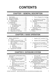
......3-1 Scanning Lamp 3-8 B. Outline of Electrical Circuit......2-2 C. Copyboard Drive Assembly...3-11 A. Turning the Scanning Lamp COPYRIGHT © 1998 CANON INC. NAMES OF PARTS 1-4 A. PC400/FC200 1-7 B. Outline 1-17 CHAPTER 2 BASIC OPERATION I . Inputs to DC Controller (2/2 2-7 F. Outline 3-1... Copier for a Long Time 1-16 V. Operation 2-5 3. Overcurrent Sensor ...........2-5 E. External View 1-4 B. Time to DC Controller (1/2 2-6 2. Outline 3-7 1. Inputs to Replace the Cartridge 1-11 2. Controlling the Intensity of the 1. CANON PC400/420/430,...
......3-1 Scanning Lamp 3-8 B. Outline of Electrical Circuit......2-2 C. Copyboard Drive Assembly...3-11 A. Turning the Scanning Lamp COPYRIGHT © 1998 CANON INC. NAMES OF PARTS 1-4 A. PC400/FC200 1-7 B. Outline 1-17 CHAPTER 2 BASIC OPERATION I . Inputs to DC Controller (2/2 2-7 F. Outline 3-1... Copier for a Long Time 1-16 V. Operation 2-5 3. Overcurrent Sensor ...........2-5 E. External View 1-4 B. Time to DC Controller (1/2 2-6 2. Outline 3-7 1. Inputs to Replace the Cartridge 1-11 2. Controlling the Intensity of the 1. CANON PC400/420/430,...
Service Manual
Page 11
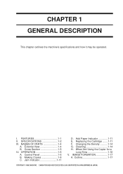
NAMES OF PARTS 1-4 A. Jam Indicator 1-11 D. Cross Section 1-5 IV. OPERATION 1-6 A. IMAGE FORMATION 1-17 A. Making Copies 1-8 C. When Not Using the Copier for a Long Time 1-16 V. CANON PC400/420/430,FC200/220 REV.0 JAN.1998 PRINTED IN JAPAN (IMPRIME AU JAPON) 1 Control Panel 1-6 B. Replacing the Cartridge ........1-11 F. FEATURES 1-1 II. Add Paper Indicator 1-11 E. Cleaning 1-14 H. ...
NAMES OF PARTS 1-4 A. Jam Indicator 1-11 D. Cross Section 1-5 IV. OPERATION 1-6 A. IMAGE FORMATION 1-17 A. Making Copies 1-8 C. When Not Using the Copier for a Long Time 1-16 V. CANON PC400/420/430,FC200/220 REV.0 JAN.1998 PRINTED IN JAPAN (IMPRIME AU JAPON) 1 Control Panel 1-6 B. Replacing the Cartridge ........1-11 F. FEATURES 1-1 II. Add Paper Indicator 1-11 E. Cleaning 1-14 H. ...

Service Manual
Page 53
... the screw when mounting the cover. 5. CANON PC400/420/430,FC200/220 REV.0 JAN.1998 PRINTED IN JAPAN (IMPRIME AU JAPON) 3-9 CHAPTER 3 EXPOSURE SYSTEM III.MECHANICAL SYSTEM Here, the copier is discussed in terms of its parts removed. Be sure to disassemble and assemble... it. Be sure to ensure electric continuity; The fixing screw for safety before disassembly or reassembly work : 1. ! COPYRIGHT © 1998 CANON INC.
... the screw when mounting the cover. 5. CANON PC400/420/430,FC200/220 REV.0 JAN.1998 PRINTED IN JAPAN (IMPRIME AU JAPON) 3-9 CHAPTER 3 EXPOSURE SYSTEM III.MECHANICAL SYSTEM Here, the copier is discussed in terms of its parts removed. Be sure to disassemble and assemble... it. Be sure to ensure electric continuity; The fixing screw for safety before disassembly or reassembly work : 1. ! COPYRIGHT © 1998 CANON INC.

Service Manual
Page 76
...; CHPTER 4 IMAGE FORMATION SYSTEM III.MECHANICAL SYSTEM Here, the copier is the reverse of disassembly. 3. Unless otherwise noted, reassembly is discussed in terms of its parts removed. 4-18 COPYRIGHT © 1998 CANON INC. Group the screws by type (length and diameter) and... location. 4. If possible, avoid operating the machine with any of the mounting screws used on the rear cover is fitted with a washer to use the washer for disassembly/assembly work . 2. CANON PC400/420/430...
...; CHPTER 4 IMAGE FORMATION SYSTEM III.MECHANICAL SYSTEM Here, the copier is the reverse of disassembly. 3. Unless otherwise noted, reassembly is discussed in terms of its parts removed. 4-18 COPYRIGHT © 1998 CANON INC. Group the screws by type (length and diameter) and... location. 4. If possible, avoid operating the machine with any of the mounting screws used on the rear cover is fitted with a washer to use the washer for disassembly/assembly work . 2. CANON PC400/420/430...
Service Manual
Page 90
... grounding wire and varistors is fitted with a washer to observe the following for safety before disassembly or reassembly work : 1. ! CANON PC400/420/430,FC200/220 REV.0 JAN.1998 PRINTED IN JAPAN (IMPRIME AU JAPON) Unless otherwise noted, reassembly is the reverse of the mounting ...characteristics and operation and how to ensure electric continuity; One of disassembly. 3. CHAPTER 5 PICK-UP/FEEDING SYSTEM V. MECHANICAL SYSTEM Here, the copier is provided with a washer to disassemble and assemble it. Disconnect the power cord for disassembly/assembly work . 2. Be sure to keep ...
... grounding wire and varistors is fitted with a washer to observe the following for safety before disassembly or reassembly work : 1. ! CANON PC400/420/430,FC200/220 REV.0 JAN.1998 PRINTED IN JAPAN (IMPRIME AU JAPON) Unless otherwise noted, reassembly is the reverse of the mounting ...characteristics and operation and how to ensure electric continuity; One of disassembly. 3. CHAPTER 5 PICK-UP/FEEDING SYSTEM V. MECHANICAL SYSTEM Here, the copier is provided with a washer to disassemble and assemble it. Disconnect the power cord for disassembly/assembly work . 2. Be sure to keep ...

Service Manual
Page 104
... a washer to use the washer for the grounding wire and varistors is provided with any of its parts removed. 6-6 COPYRIGHT © 1998 CANON INC. MECHANICAL SYSTEM Here, the copier is the reverse of the mounting screws used on the rear cover is fitted with the screw when... mounting the cover. 5. One of disassembly. 3. Disconnect the power cord for disassembly/assembly work . 2. CANON PC400/420/430,FC200/220 REV.0 JAN...
... a washer to use the washer for the grounding wire and varistors is provided with any of its parts removed. 6-6 COPYRIGHT © 1998 CANON INC. MECHANICAL SYSTEM Here, the copier is the reverse of the mounting screws used on the rear cover is fitted with the screw when... mounting the cover. 5. One of disassembly. 3. Disconnect the power cord for disassembly/assembly work . 2. CANON PC400/420/430,FC200/220 REV.0 JAN...

Service Manual
Page 115
One of its parts removed. be sure to use the washer for the grounding wire and varistors is fitted with a washer to ensure electric continuity; CANON PC400/420/430,FC200/220 REV.0 JAN.1998 PRINTED IN JAPAN (IMPRIME AU JAPON) 7-3 Group the screws by type (length and... diameter) and location. 4. Be sure to keep the washer with any of disassembly. 3. The fixing screw for reassembly. 6. CHAPTER 7 EXTERNALS/AUXILIARY MECHANISMS II.MECHANICAL SYSTEM Here, the copier...
One of its parts removed. be sure to use the washer for the grounding wire and varistors is fitted with a washer to ensure electric continuity; CANON PC400/420/430,FC200/220 REV.0 JAN.1998 PRINTED IN JAPAN (IMPRIME AU JAPON) 7-3 Group the screws by type (length and... diameter) and location. 4. Be sure to keep the washer with any of disassembly. 3. The fixing screw for reassembly. 6. CHAPTER 7 EXTERNALS/AUXILIARY MECHANISMS II.MECHANICAL SYSTEM Here, the copier...

Service Manual
Page 130
... II. Note: Do not touch the transfer charging roller inside the copier at least one hour before unpacking it stops, and press the open/close button to the front.) Transfer charging roller 8-2 COPYRIGHT © 1998 CANON INC. parts. • Slide out the manual feed tray. • Slide out... the delivery tray. 4 Move the copyboard to the left until it . CANON PC400/420/430,FC200/220 REV.0 JAN.1998 PRINTED IN JAPAN (IMPRIME AU JAPON) The phenomenon is expected, leave the copier alone at the site...
... II. Note: Do not touch the transfer charging roller inside the copier at least one hour before unpacking it stops, and press the open/close button to the front.) Transfer charging roller 8-2 COPYRIGHT © 1998 CANON INC. parts. • Slide out the manual feed tray. • Slide out... the delivery tray. 4 Move the copyboard to the left until it . CANON PC400/420/430,FC200/220 REV.0 JAN.1998 PRINTED IN JAPAN (IMPRIME AU JAPON) The phenomenon is expected, leave the copier alone at the site...
Service Manual
Page 185
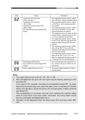
... position sensor (Q902) does not go ON 1.2 sec. After self diagnosis has gone ON, the copier may have blown; To reset, disconnect the power plug once, open the upper cover, or wait...) • Copyboard position sensor PCB (Q902; otherwise, the fixing heater would become overheated, damaging parts near it OFF and then ON. after copying operation has started moving in reverse from resetting the ...Q902) is higher than specified. COPYRIGHT © 1998 CANON INC. This consideration is ON 1.5 sec. CANON PC400/420/430,FC200/220 REV.0 JAN.1998 PRINTED IN JAPAN (IMPRIME AU JAPON) 10-41...
... position sensor (Q902) does not go ON 1.2 sec. After self diagnosis has gone ON, the copier may have blown; To reset, disconnect the power plug once, open the upper cover, or wait...) • Copyboard position sensor PCB (Q902; otherwise, the fixing heater would become overheated, damaging parts near it OFF and then ON. after copying operation has started moving in reverse from resetting the ...Q902) is higher than specified. COPYRIGHT © 1998 CANON INC. This consideration is ON 1.5 sec. CANON PC400/420/430,FC200/220 REV.0 JAN.1998 PRINTED IN JAPAN (IMPRIME AU JAPON) 10-41...


