User Manual
Page 6
CONTENTS INTRODUCTION 1 Conventions 1 Safety Precautions 5 Daily Maintenance 5 Installation Location 7 Power Supply 8 Carrying ...8 Chapter 1 DR-7580/9080C 1.1 Features of the DR-7580/9080C 10 1.2 Packaging: What Is in the Box 12 1.3 Part Names 13 ◆ Front View 13 ◆ Rear ... the SCSI ID and Terminator 20 USB Connections 22 ◆ USB 2.0 Interface Cards 22 ◆ Connecting a USB Interface Cable 23 Connecting the Power Cord 23 2.3 Preparing for Paper Feed and Eject 24 Preparing the Document Tray Extension 24 Preparing the Document Eject Tray Extension 25 ◆ ...
CONTENTS INTRODUCTION 1 Conventions 1 Safety Precautions 5 Daily Maintenance 5 Installation Location 7 Power Supply 8 Carrying ...8 Chapter 1 DR-7580/9080C 1.1 Features of the DR-7580/9080C 10 1.2 Packaging: What Is in the Box 12 1.3 Part Names 13 ◆ Front View 13 ◆ Rear ... the SCSI ID and Terminator 20 USB Connections 22 ◆ USB 2.0 Interface Cards 22 ◆ Connecting a USB Interface Cable 23 Connecting the Power Cord 23 2.3 Preparing for Paper Feed and Eject 24 Preparing the Document Tray Extension 24 Preparing the Document Eject Tray Extension 25 ◆ ...
User Manual
Page 8
5.2 Setting in the User Mode 60 How to Set the User Mode 62 Chapter 6 Troubleshooting 6.1 When the Scanner Is Not Recognized 64 SCSI Connections 64 USB Connections 66 6.2 Clearing Paper Jams 67 Paper Jam in the Paper Feed Unit 67 Paper Jam in the Paper Exit Section 70 6.3 Paper...Not Normal 74 6.5 When an Error Code Is Displayed 75 Chapter 7 Daily Cleaning 7.1 Daily Cleaning 80 Cleaning the Main Unit 80 Cleaning the Document Detection Sensor 81 Cleaning the Scanning Glasses and Rollers 81 Cleaning the Shading Plates 85 Cleaning the Guide Plate (When Using the Imprinter 87 Cleaning...
5.2 Setting in the User Mode 60 How to Set the User Mode 62 Chapter 6 Troubleshooting 6.1 When the Scanner Is Not Recognized 64 SCSI Connections 64 USB Connections 66 6.2 Clearing Paper Jams 67 Paper Jam in the Paper Feed Unit 67 Paper Jam in the Paper Exit Section 70 6.3 Paper...Not Normal 74 6.5 When an Error Code Is Displayed 75 Chapter 7 Daily Cleaning 7.1 Daily Cleaning 80 Cleaning the Main Unit 80 Cleaning the Document Detection Sensor 81 Cleaning the Scanning Glasses and Rollers 81 Cleaning the Shading Plates 85 Cleaning the Guide Plate (When Using the Imprinter 87 Cleaning...

User Manual
Page 16
Power Cord DR-7580/9080C Setup Disc Instructions (this manual) QUICK REFERENCE TROUUSBSECLFEAUSNLHNFOIENOAGTTUINBRAGESSICS DOCUMENT SCANNER Quick Reference Guide USB Cable • The setup disc is in the Instructions. • Item included in the Box? If any items are missing, contact your sales representative. Make sure that you have everything. Check every item you have removed from the box. and Canada only) 12 Chapter 1 DR-7580/9080C Packaging: What Is in this package may change without notice. Warranty Card (U.S.A.
Power Cord DR-7580/9080C Setup Disc Instructions (this manual) QUICK REFERENCE TROUUSBSECLFEAUSNLHNFOIENOAGTTUINBRAGESSICS DOCUMENT SCANNER Quick Reference Guide USB Cable • The setup disc is in the Instructions. • Item included in the Box? If any items are missing, contact your sales representative. Make sure that you have everything. Check every item you have removed from the box. and Canada only) 12 Chapter 1 DR-7580/9080C Packaging: What Is in this package may change without notice. Warranty Card (U.S.A.
User Manual
Page 18
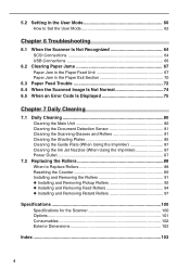
CAUTION ◆ Connectors (Bottom View) USB Connector Connect a Hi-Speed USB 2.0 compatible cable. (See p.22.) SCSI Connectors Connect a half-pitch 50 pin (pin type) SCSI cable. (See p.19.) DIP Switch This switch is for setting the SCSI ID and turning ON or OFF the terminator. (See p.20.) 14 Air Vent To avoid overheating and causing a fire, never block the air vents on the rear of the scanner. Chapter 1 DR-7580/9080C ◆ Rear View Connectors Power Cord Connector Connect the power cord provided with the scanner to this connector.
CAUTION ◆ Connectors (Bottom View) USB Connector Connect a Hi-Speed USB 2.0 compatible cable. (See p.22.) SCSI Connectors Connect a half-pitch 50 pin (pin type) SCSI cable. (See p.19.) DIP Switch This switch is for setting the SCSI ID and turning ON or OFF the terminator. (See p.20.) 14 Air Vent To avoid overheating and causing a fire, never block the air vents on the rear of the scanner. Chapter 1 DR-7580/9080C ◆ Rear View Connectors Power Cord Connector Connect the power cord provided with the scanner to this connector.
User Manual
Page 21
Chapter 2 Preparation Before Use This chapter describes the procedure from scanner connection through to turning ON the power. 2.1 Checking Your Operating Environment 18 2.2 Connecting to a Computer 19 SCSI Connections 19 USB Connections 22 Connecting the Power Cord 23 2.3 Preparing for Paper Feed and Eject 24 Preparing the Document Tray Extension 24 Preparing the Document Eject Tray Extension 25 2.4 Turning ON/OFF the Power 27 Turning ON the Power 27 Recognizing the Scanner 28 Turning OFF the Power 30
Chapter 2 Preparation Before Use This chapter describes the procedure from scanner connection through to turning ON the power. 2.1 Checking Your Operating Environment 18 2.2 Connecting to a Computer 19 SCSI Connections 19 USB Connections 22 Connecting the Power Cord 23 2.3 Preparing for Paper Feed and Eject 24 Preparing the Document Tray Extension 24 Preparing the Document Eject Tray Extension 25 2.4 Turning ON/OFF the Power 27 Turning ON the Power 27 Recognizing the Scanner 28 Turning OFF the Power 30

User Manual
Page 22
...Checking Your Operating Environment Your computer system must meet the following conditions to use the DR-7580/9080C. ● IBM PC/AT or compatible machines that is compatible with this scanner or Hi-Speed USB 2.0 interface card (See "Connecting to transfer data may slow down or the time...8226; Microsoft Windows NT 4.0 Workstation SP6 • Microsoft Windows 2000 Professional SP3 or later • Microsoft Windows XP SP1 or later For USB • Microsoft Windows 98SE • Microsoft Windows Me • Microsoft Windows 2000 Professional SP3 or later • Microsoft Windows XP SP1 or...
...Checking Your Operating Environment Your computer system must meet the following conditions to use the DR-7580/9080C. ● IBM PC/AT or compatible machines that is compatible with this scanner or Hi-Speed USB 2.0 interface card (See "Connecting to transfer data may slow down or the time...8226; Microsoft Windows NT 4.0 Workstation SP6 • Microsoft Windows 2000 Professional SP3 or later • Microsoft Windows XP SP1 or later For USB • Microsoft Windows 98SE • Microsoft Windows Me • Microsoft Windows 2000 Professional SP3 or later • Microsoft Windows XP SP1 or...
User Manual
Page 23
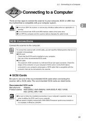
...of the recommended SCSI cards when connecting the scanner with AHA-2930LP because synchronous transfer is CAUTION running. ■ Do not connect both SCSI and USB interface cables at the same time. ■ Turn OFF the computer and the scanner before changing the cable format. SCSI Connections... Connect the scanner to your computer system. 2 ■ Do not turn OFF the scanner or remove any interface cables when an...
...of the recommended SCSI cards when connecting the scanner with AHA-2930LP because synchronous transfer is CAUTION running. ■ Do not connect both SCSI and USB interface cables at the same time. ■ Turn OFF the computer and the scanner before changing the cable format. SCSI Connections... Connect the scanner to your computer system. 2 ■ Do not turn OFF the scanner or remove any interface cables when an...

User Manual
Page 24
..., insert the other SCSI cable into one of the connectors on the bottom of the scanner. Connect your computer to the table above. Two SCSI connectors are turned OFF. ■ Do not connect both SCSI and USB interface cables at the same time. Set unique SCSI IDs to turn it ON. Insert... DIP switch towards you connect the SCSI cable, make sure that the scanner and the computer are located on the rear of the SCSI cable into the SCSI device in SCSI devices or SCSI devices connected to the computer. 20 USB Connector (cannot be connected) SCSI Connectors Power Cord Connector SCSI Cable...
..., insert the other SCSI cable into one of the connectors on the bottom of the scanner. Connect your computer to the table above. Two SCSI connectors are turned OFF. ■ Do not connect both SCSI and USB interface cables at the same time. Set unique SCSI IDs to turn it ON. Insert... DIP switch towards you connect the SCSI cable, make sure that the scanner and the computer are located on the rear of the SCSI cable into the SCSI device in SCSI devices or SCSI devices connected to the computer. 20 USB Connector (cannot be connected) SCSI Connectors Power Cord Connector SCSI Cable...
User Manual
Page 26
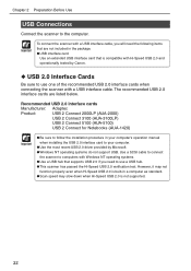
... your computer. ● Use the most recent USB 2.0 driver provided by Canon. ◆ USB 2.0 Interface Cards Be sure to the computer. Chapter 2 Preparation Before Use USB Connections Connect the scanner to use a USB hub. ● This scanner has passed the Hi-Speed USB 2.0 verification test. Important To connect the scanner with a USB interface cable, you need the following items that...
... your computer. ● Use the most recent USB 2.0 driver provided by Canon. ◆ USB 2.0 Interface Cards Be sure to the computer. Chapter 2 Preparation Before Use USB Connections Connect the scanner to use a USB hub. ● This scanner has passed the Hi-Speed USB 2.0 verification test. Important To connect the scanner with a USB interface cable, you need the following items that...

User Manual
Page 27
...source. ■ Use only the power cord and plug provided with the scanner. ■ Before you use only the power cord provided with another object. If you connect the power cord, be connected) 2 USB Interface Cable Connecting the Power Cord Connect the power cord. CAUTION SCSI Connectors...cable. 23 Be sure to your hands are wet. ■ Never plug the scanner into an outlet shared with the scanner. Failure to a Computer ◆ Connecting a USB Interface Cable Do not connect both a SCSI cable and USB interface cable at the same time. 2.2 Connecting to do so might cause a...
...source. ■ Use only the power cord and plug provided with the scanner. ■ Before you use only the power cord provided with another object. If you connect the power cord, be connected) 2 USB Interface Cable Connecting the Power Cord Connect the power cord. CAUTION SCSI Connectors...cable. 23 Be sure to your hands are wet. ■ Never plug the scanner into an outlet shared with the scanner. Failure to a Computer ◆ Connecting a USB Interface Cable Do not connect both a SCSI cable and USB interface cable at the same time. 2.2 Connecting to do so might cause a...

User Manual
Page 33
... the Found New Hardware Wizard" screen. ● The DR-7580 will be registered as "CANON DR-7580 SCSI" or "CANON DR-7580 Note USB" in the "Imaging Device" directory. ● The DR-9080C will be registered as "CANON DR-9080C SCSI" or "CANON DR-9080C USB" in the "Hardware Installation" dialog box. Important If you cancel the scanner recognition operation before changing the connections, and then...
... the Found New Hardware Wizard" screen. ● The DR-7580 will be registered as "CANON DR-7580 SCSI" or "CANON DR-7580 Note USB" in the "Imaging Device" directory. ● The DR-9080C will be registered as "CANON DR-9080C SCSI" or "CANON DR-9080C USB" in the "Hardware Installation" dialog box. Important If you cancel the scanner recognition operation before changing the connections, and then...
User Manual
Page 67
Chapter 6 Troubleshooting This chapter describes the trouble that may occur on the DR-7580/9080C and how to correct it. 6.1 When the Scanner Is Not Recognized 64 SCSI Connections 64 USB Connections 66 6.2 Clearing Paper jams 67 Paper Jam in the Paper Feed Unit .......... 67 Paper Jam in the Paper Exit Section ....... 70 6.3 Paper Feed Trouble 72 6.4 When the Scanned Image Is Not Normal 74 6.5 When an Error Code Is Displayed .....75
Chapter 6 Troubleshooting This chapter describes the trouble that may occur on the DR-7580/9080C and how to correct it. 6.1 When the Scanner Is Not Recognized 64 SCSI Connections 64 USB Connections 66 6.2 Clearing Paper jams 67 Paper Jam in the Paper Feed Unit .......... 67 Paper Jam in the Paper Exit Section ....... 70 6.3 Paper Feed Trouble 72 6.4 When the Scanned Image Is Not Normal 74 6.5 When an Error Code Is Displayed .....75
User Manual
Page 70
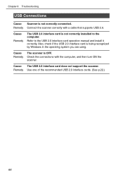
... with the computer, and then turn ON the scanner. Also, check if the USB 2.0 interface card is OFF. Cause The USB 2.0 interface card dose not support the scanner. Cause Remedy The scanner is being recognized by Windows in the operating system you are using. Cause Remedy The USB 2.0 interface card is not correctly connected. Refer to...
... with the computer, and then turn ON the scanner. Also, check if the USB 2.0 interface card is OFF. Cause The USB 2.0 interface card dose not support the scanner. Cause Remedy The scanner is being recognized by Windows in the operating system you are using. Cause Remedy The USB 2.0 interface card is not correctly connected. Refer to...

User Manual
Page 104
Specifications Specifications for the Scanner Type Document size Document feeding Scanning method Desktop sheet fed type Width: Length: 2.2" to 12"/55 to 305 mm 2.8" to 17.0"/70 to 432 mm 2.8" to 39.4" /70 to 1,000 mm (Long Document mode) Thickness: 0.002" to 0.006"/0.06 to 0....600 x 600dpi/400 x 400dpi/300 x 300dpi/ 240 x 240dpi/200 x 200dpi/150 x 150dpi/ 100 x 100dpi Scanning speed (max.) DR-9080C DR-7580 Black and White Simplex 200 x 200 dpi 90 ppm 75 ppm 300 x 300 dpi 90 ppm 75 ppm Duplex 200 x 200 ... (A4): Max. 200 sheets (80g/m2 or 20 lb bond) Interface SCSI-III/USB 2.0 100
Specifications Specifications for the Scanner Type Document size Document feeding Scanning method Desktop sheet fed type Width: Length: 2.2" to 12"/55 to 305 mm 2.8" to 17.0"/70 to 432 mm 2.8" to 39.4" /70 to 1,000 mm (Long Document mode) Thickness: 0.002" to 0.006"/0.06 to 0....600 x 600dpi/400 x 400dpi/300 x 300dpi/ 240 x 240dpi/200 x 200dpi/150 x 150dpi/ 100 x 100dpi Scanning speed (max.) DR-9080C DR-7580 Black and White Simplex 200 x 200 dpi 90 ppm 75 ppm 300 x 300 dpi 90 ppm 75 ppm Duplex 200 x 200 ... (A4): Max. 200 sheets (80g/m2 or 20 lb bond) Interface SCSI-III/USB 2.0 100
User Manual
Page 108
...15 Stop key 15 Stopper 13, 25 - Troubleshooting 63 Turning OFF the power 30 Turning ON the power 27 - Operating environment 18 USB connector 14 User mode 60 - P - How to use patch code sheets ... 53 PATCH II 54 PATCH T 54 Power cord... switch 13, 27 - SCSI connections - How to use the software 36 - Unpacking the scanner 12 Upper scanner 13 USB connections - T - Connecting to set the user mode 62 104 How to a computer .......... 22 - Panel- Recognizing the scanner 28 Retard roller 97 - Connecting to a computer .......... 19 - U - - feeding 44...
...15 Stop key 15 Stopper 13, 25 - Troubleshooting 63 Turning OFF the power 30 Turning ON the power 27 - Operating environment 18 USB connector 14 User mode 60 - P - How to use patch code sheets ... 53 PATCH II 54 PATCH T 54 Power cord... switch 13, 27 - SCSI connections - How to use the software 36 - Unpacking the scanner 12 Upper scanner 13 USB connections - T - Connecting to set the user mode 62 104 How to a computer .......... 22 - Panel- Recognizing the scanner 28 Retard roller 97 - Connecting to a computer .......... 19 - U - - feeding 44...

