NL200/NL201 Network Link Interface
Page 3
... for installation services performed by Campbell such as programming to customer specifications, electrical connections to repairing or replacing (at Campbell's option) defective products, which shall be free from date of Campbell's product warranty. Campbell is limited to products manufactured by surface carrier prepaid within the continental United States of nature, or shipping damage. are warranted only to the limits extended by Campbell Scientific, Inc. ("Campbell") to...
... for installation services performed by Campbell such as programming to customer specifications, electrical connections to repairing or replacing (at Campbell's option) defective products, which shall be free from date of Campbell's product warranty. Campbell is limited to products manufactured by surface carrier prepaid within the continental United States of nature, or shipping damage. are warranted only to the limits extended by Campbell Scientific, Inc. ("Campbell") to...
NL200/NL201 Network Link Interface
Page 6
...setup 4 NL201 5 Bridge Mode enabled 5 Bridge Mode disabled 6 ii NL200/201 Driver Installation Instructions ...........D-1 D.1 Installing on Windows XP D-1 D.2 Installing on Windows Vista D-3 D.3 Installing on Windows 7 D-4 D.4 Oops! What if you plug the NL200/NL201 into your computer before installing the drivers D-4 E. Sending a New OS to the NL200/201 22 8. Glossary A-1 B. NL200/201 Settings C-1 C.1 Main Tab C-1 C.2 RS-232 Tab C-4 C.3 CS I /O B-1 B.2 RS-232 B-1 B.3 Ethernet B-2 B.4 USB B-2 B.5 Power B-2 B.6 LEDs B-3 B.7 Power Jumper (NL201 only B-3 C. Troubleshooting...
...setup 4 NL201 5 Bridge Mode enabled 5 Bridge Mode disabled 6 ii NL200/201 Driver Installation Instructions ...........D-1 D.1 Installing on Windows XP D-1 D.2 Installing on Windows Vista D-3 D.3 Installing on Windows 7 D-4 D.4 Oops! What if you plug the NL200/NL201 into your computer before installing the drivers D-4 E. Sending a New OS to the NL200/201 22 8. Glossary A-1 B. NL200/201 Settings C-1 C.1 Main Tab C-1 C.2 RS-232 Tab C-4 C.3 CS I /O B-1 B.2 RS-232 B-1 B.3 Ethernet B-2 B.4 USB B-2 B.5 Power B-2 B.6 LEDs B-3 B.7 Power Jumper (NL201 only B-3 C. Troubleshooting...
NL200/NL201 Network Link Interface
Page 9
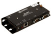
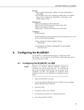
.... Use a shielded Ethernet cable and external surge protection. Introduction The NL200/201 Network Link Interface allows Campbell Scientific dataloggers and peripherals to communicate over an Ethernet / Internet network connection. 3.1 Physical Setup Using the supplied serial cable, connect the NL201's CS I/O port to a datalogger's CS I /O or USB. Keep RS-232 and CS I /O port. This serial to Ethernet interface can be connected to the datalogger's CS I /O connections short. 3. The latest operating systems can be downloaded from...
.... Use a shielded Ethernet cable and external surge protection. Introduction The NL200/201 Network Link Interface allows Campbell Scientific dataloggers and peripherals to communicate over an Ethernet / Internet network connection. 3.1 Physical Setup Using the supplied serial cable, connect the NL201's CS I/O port to a datalogger's CS I /O or USB. Keep RS-232 and CS I /O port. This serial to Ethernet interface can be connected to the datalogger's CS I /O connections short. 3. The latest operating systems can be downloaded from...
NL200/NL201 Network Link Interface
Page 11
..., Network Mask, and Default Gateway. Input the NL200/201's IP address and port number. An IPv4 address may 3 See Appendix D, NL200/201 Driver Installation Instructions, for the first time. NL200/201 Network Link Interface 3.2 Configuring the NL200/201 NOTE INSTALL THE DEVICE DRIVER BEFORE plugging the NL200/201 into your PC for instructions on installing the device driver. • Ensure the NL200/201 is powered. • Connect the supplied USB cable between a USB port...
..., Network Mask, and Default Gateway. Input the NL200/201's IP address and port number. An IPv4 address may 3 See Appendix D, NL200/201 Driver Installation Instructions, for the first time. NL200/201 Network Link Interface 3.2 Configuring the NL200/201 NOTE INSTALL THE DEVICE DRIVER BEFORE plugging the NL200/201 into your PC for instructions on installing the device driver. • Ensure the NL200/201 is powered. • Connect the supplied USB cable between a USB port...
NL200/NL201 Network Link Interface
Page 13
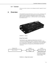
... Channel 1 or 3) NOTE: Devices connected to bridge Ethernet and CS I/O communications (Bridge Mode enabled). Overview The NL200/201 Network Link Interface is used to communicate with Campbell Scientific dataloggers and peripherals using the LoggerNet Connect Screen. 4. The NL200/201 includes a CS I/O port and an RS-232 port for providing access to your datalogger using an Ethernet 10/100 Mbps communications link. A USB device port is a device used for...
... Channel 1 or 3) NOTE: Devices connected to bridge Ethernet and CS I/O communications (Bridge Mode enabled). Overview The NL200/201 Network Link Interface is used to communicate with Campbell Scientific dataloggers and peripherals using the LoggerNet Connect Screen. 4. The NL200/201 includes a CS I/O port and an RS-232 port for providing access to your datalogger using an Ethernet 10/100 Mbps communications link. A USB device port is a device used for...
NL200/NL201 Network Link Interface
Page 17
... D, NL200/201 Driver Installation Instructions, for instructions on installing the device driver. • Ensure the NL200/201 is powered. • Connect the supplied USB cable between a USB port on the NL200/201. • Open DevConfig. • Under Device Type, select "NL200". • Click the Browse button next to "Communication Port". • Select the port labeled "NL200". 9 You can connect your NL200/201 to DevConfig using the Device Configuration...
... D, NL200/201 Driver Installation Instructions, for instructions on installing the device driver. • Ensure the NL200/201 is powered. • Connect the supplied USB cable between a USB port on the NL200/201. • Open DevConfig. • Under Device Type, select "NL200". • Click the Browse button next to "Communication Port". • Select the port labeled "NL200". 9 You can connect your NL200/201 to DevConfig using the Device Configuration...

NL200/NL201 Network Link Interface
Page 19
... over port 23. • Input the NL200/201 Admin Password (default password is nl200). • Type help to see a list of the functionality available when connected to the NL200/201 through all of the NL200/201. • As each NL200/201 setting is shown, press Enter to the device will be required. Type a new value and press Enter to change the...
... over port 23. • Input the NL200/201 Admin Password (default password is nl200). • Type help to see a list of the functionality available when connected to the NL200/201 through all of the NL200/201. • As each NL200/201 setting is shown, press Enter to the device will be required. Type a new value and press Enter to change the...
NL200/NL201 Network Link Interface
Page 20
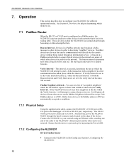
... as neighbors. 7.1.1 Physical Setup Using the supplied serial cable, connect the NL200/201's CS I /O port is powered up by the current device without being routed through the barrel-connector jack located on its routing table. You can be powered if connected via CS I /O or RS-232 port, respectively. Operation This section describes how to hear from devices with directly by inspecting the Power LED. 7.1.2 Configuring the...
... as neighbors. 7.1.1 Physical Setup Using the supplied serial cable, connect the NL200/201's CS I /O port is powered up by the current device without being routed through the barrel-connector jack located on its routing table. You can be powered if connected via CS I /O or RS-232 port, respectively. Operation This section describes how to hear from devices with directly by inspecting the Power LED. 7.1.2 Configuring the...
NL200/NL201 Network Link Interface
Page 21
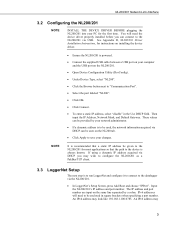
... its default value.) 7.1.3 LoggerNet Setup • In LoggerNet's Setup Screen, press Add Root and choose "IPPort". Often the default values can be used . Unless firewall issues exist, it is 6785. Input the NL200/201's IP address and port number. However, an allowed neighbors list can be useful in DevConfig (see Section 6, Configuring the NL200/201). • On the NL200 tab: o Set Bridge Mode...
... its default value.) 7.1.3 LoggerNet Setup • In LoggerNet's Setup Screen, press Add Root and choose "IPPort". Often the default values can be used . Unless firewall issues exist, it is 6785. Input the NL200/201's IP address and port number. However, an allowed neighbors list can be useful in DevConfig (see Section 6, Configuring the NL200/201). • On the NL200 tab: o Set Bridge Mode...

NL200/NL201 Network Link Interface
Page 22
... to your datalogger using the LoggerNet Connect Screen. 7.2 Bridge Mode 7.2.1 Physical Setup Using the supplied serial cable, connect the NL201's CS I/O port to your network. Connect the NL200/201 to your network using an Ethernet cable, attaching one end of the datalogger. • Press Apply to save the changes. NL200/201 Network Link Interface • Add a PakBus Router (pbRouter). FIGURE 7-1. Alternatively, power the NL200 or NL201 through the barrel-connector jack located on the...
... to your datalogger using the LoggerNet Connect Screen. 7.2 Bridge Mode 7.2.1 Physical Setup Using the supplied serial cable, connect the NL201's CS I/O port to your network. Connect the NL200/201 to your network using an Ethernet cable, attaching one end of the datalogger. • Press Apply to save the changes. NL200/201 Network Link Interface • Add a PakBus Router (pbRouter). FIGURE 7-1. Alternatively, power the NL200 or NL201 through the barrel-connector jack located on the...

NL200/NL201 Network Link Interface
Page 23
... • Connect a serial cable from its value in FIGURE 7-2 below.) • In LoggerNet's Setup Screen, press Add Root and choose "IPPort". Press Connect to connect to the datalogger via the Ethernet port. (See example in the Status Table. DNS server settings are correct by a colon. (The datalogger's default port number is not connected, the TCP/IP settings will find the information acquired by your network administrator...
... • Connect a serial cable from its value in FIGURE 7-2 below.) • In LoggerNet's Setup Screen, press Add Root and choose "IPPort". Press Connect to connect to the datalogger via the Ethernet port. (See example in the Status Table. DNS server settings are correct by a colon. (The datalogger's default port number is not connected, the TCP/IP settings will find the information acquired by your network administrator...

NL200/NL201 Network Link Interface
Page 24
... the NL200/201). 16 Alternatively, power the NL200 or NL201 through the barrel-connector jack located on the edge of the cable to the NL200/201's Ethernet port and the other end to your network. NL200/201 Network Link Interface FIGURE 7-2. Bridge mode LoggerNet setup 7.2.5 Connect You are now ready to connect to your datalogger using the LoggerNet Connect Screen. 7.3 Serial Server The NL200/201 can tunnel...
... the NL200/201). 16 Alternatively, power the NL200 or NL201 through the barrel-connector jack located on the edge of the cable to the NL200/201's Ethernet port and the other end to your network. NL200/201 Network Link Interface FIGURE 7-2. Bridge mode LoggerNet setup 7.2.5 Connect You are now ready to connect to your datalogger using the LoggerNet Connect Screen. 7.3 Serial Server The NL200/201 can tunnel...

NL200/NL201 Network Link Interface
Page 29
... | TLS Proxy Server Tab • Set the TLS Proxy Server setting to the datalogger and forward the unencrypted data. This address must specify an IP address and TCP port number for Configuration A, connect to the datalogger using DevConfig and select the CS I /O Interface IP Address to be changed if desired. The default value for the datalogger's PakBus/TCP server...
... | TLS Proxy Server Tab • Set the TLS Proxy Server setting to the datalogger and forward the unencrypted data. This address must specify an IP address and TCP port number for Configuration A, connect to the datalogger using DevConfig and select the CS I /O Interface IP Address to be changed if desired. The default value for the datalogger's PakBus/TCP server...

NL200/NL201 Network Link Interface
Page 30
... to the NL200/NL201's CS I/O IP Interface Identifier setting. Once the private key and certificate are behind firewalls. Input the NL200/201's IP address (or press the browse button to the NL200/201. The private key and certificate cannot be initialized through a direct USB connection to select it from the Settings Editor | TLS tab in DevConfig. Applications 8.1 Working Around Firewalls The...
... to the NL200/NL201's CS I/O IP Interface Identifier setting. Once the private key and certificate are behind firewalls. Input the NL200/201's IP address (or press the browse button to the NL200/201. The private key and certificate cannot be initialized through a direct USB connection to select it from the Settings Editor | TLS tab in DevConfig. Applications 8.1 Working Around Firewalls The...
NL200/NL201 Network Link Interface
Page 32
... to connect from are able to communicate with each other. (Your network administrator can also try moving the existing Ethernet cable to a functioning system to Campbell Scientific technical support. Wait 10 seconds and then plug them on your NL200/201. Check power indicator lights to make sure your devices are using the NL200/201. This is securely plugged in or turn them...
... to connect from are able to communicate with each other. (Your network administrator can also try moving the existing Ethernet cable to a functioning system to Campbell Scientific technical support. Wait 10 seconds and then plug them on your NL200/201. Check power indicator lights to make sure your devices are using the NL200/201. This is securely plugged in or turn them...
NL200/NL201 Network Link Interface
Page 33
... have installed the latest drivers for CS I /O serial server, in the NL200/201. • Note that any other SDC device attached to ping the NL200/201 from our website at www.campbellsci.com. 7. NL200/201 Network Link Interface • When Bridge Mode is enabled, the datalogger controls how the IP address is using the Defaults command in LoggerNet Setup. 9. The default port number...
... have installed the latest drivers for CS I /O serial server, in the NL200/201. • Note that any other SDC device attached to ping the NL200/201 from our website at www.campbellsci.com. 7. NL200/201 Network Link Interface • When Bridge Mode is enabled, the datalogger controls how the IP address is using the Defaults command in LoggerNet Setup. 9. The default port number...
NL200/NL201 Network Link Interface
Page 35
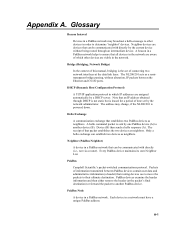
... static but is powered down. PakBus Campbell Scientific's packet-switched communications protocol. Appendix A. A beacon in order to their ultimate destination. The receipt of which IP addresses are devices that routing devices use to move the packets to determine "neighbor" devices. PakBus devices examine the header information and then either remove the header (at the data link layer. A-1 Hello...
... static but is powered down. PakBus Campbell Scientific's packet-switched communications protocol. Appendix A. A beacon in order to their ultimate destination. The receipt of which IP addresses are devices that routing devices use to move the packets to determine "neighbor" devices. PakBus devices examine the header information and then either remove the header (at the data link layer. A-1 Hello...

NL200/NL201 Network Link Interface
Page 44
... RS-232 port. NL200/201 Settings rate by the Admin Password. Setting the Ethernet Speed/Duplex Configuration to "Auto" will buffer up the data (up to 1500 bytes) and immediately attempt to access the NL200/201. TCP Configuration Port Number The default TCP port number for an incoming TCP connection from its default. (range 1..65535) C.2 RS-232 Tab RS-232 Configuration This setting controls which process...
... RS-232 port. NL200/201 Settings rate by the Admin Password. Setting the Ethernet Speed/Duplex Configuration to "Auto" will buffer up the data (up to 1500 bytes) and immediately attempt to access the NL200/201. TCP Configuration Port Number The default TCP port number for an incoming TCP connection from its default. (range 1..65535) C.2 RS-232 Tab RS-232 Configuration This setting controls which process...

NL200/NL201 Network Link Interface
Page 45
... Serial Server Port Number This setting is used . This setting allows the user to disable the RTS line if needed so that it is configured as the device does not know the frequency or nature of the RS-232 port. Set to use port 502. (range 1..65535) RS-232 Baud Rate This setting specifies the baud rate of the expected data. The connected device must open another connection...
... Serial Server Port Number This setting is used . This setting allows the user to disable the RTS line if needed so that it is configured as the device does not know the frequency or nature of the RS-232 port. Set to use port 502. (range 1..65535) RS-232 Baud Rate This setting specifies the baud rate of the expected data. The connected device must open another connection...

NL200/NL201 Network Link Interface
Page 47
..., or 11. NL200/201 Settings C.3 CS I/O Tab CS I /O TCP Timeout This setting, in units of the serial server is specified in the "RS-232 TCP Port Number" setting. The port number of the listening connection is set. The port number of the listening connection is running and a port number associated with which process will be forwarded to change this TCP connection. The socket of a specific server is uniquely identified...
..., or 11. NL200/201 Settings C.3 CS I/O Tab CS I /O TCP Timeout This setting, in units of the serial server is specified in the "RS-232 TCP Port Number" setting. The port number of the listening connection is set. The port number of the listening connection is running and a port number associated with which process will be forwarded to change this TCP connection. The socket of a specific server is uniquely identified...
