
Open Path Eddy Covariance (OPEC)
Page 3
... the limits extended by Campbell such as programming to customer specifications, electrical connections to be the sole and exclusive remedy under this warranty. Batteries, fine-wire thermocouples, desiccant, and other locations, Campbell will return such products by Campbell, and product specific training, is in the corresponding Campbell pricelist or product manual. Campbell is limited to Campbell. Warranty "PRODUCTS MANUFACTURED BY CAMPBELL SCIENTIFIC, INC. The customer...
... the limits extended by Campbell such as programming to customer specifications, electrical connections to be the sole and exclusive remedy under this warranty. Batteries, fine-wire thermocouples, desiccant, and other locations, Campbell will return such products by Campbell, and product specific training, is in the corresponding Campbell pricelist or product manual. Campbell is limited to Campbell. Warranty "PRODUCTS MANUFACTURED BY CAMPBELL SCIENTIFIC, INC. The customer...

Open Path Eddy Covariance (OPEC)
Page 6
... United States (2004) ... A-3. A-1 A declination angle East of True North (positive) is subtracted from 0 (360) degrees to read a Campbell Scientific TOB1 data file..... 26 Folder that contains the raw TOB1 time series data files 26 Completed Interpreter screen 27 Estimated sample frequency and correct sample frequency 27 Default EdiRe processing list created by the Interpreter 28 Output file location as part of the processing list...
... United States (2004) ... A-3. A-1 A declination angle East of True North (positive) is subtracted from 0 (360) degrees to read a Campbell Scientific TOB1 data file..... 26 Folder that contains the raw TOB1 time series data files 26 Completed Interpreter screen 27 Estimated sample frequency and correct sample frequency 27 Default EdiRe processing list created by the Interpreter 28 Output file location as part of the processing list...
Open Path Eddy Covariance (OPEC)
Page 9
...install and operate a Campbell Scientific Open-Path Eddy-Covariance System (OPEC). Doing so will serve as a guide to trouble shoot the station near the office. System Description The Campbell Scientific ...Campbell Scientific and other scalars between the atmosphere and earth's surface. It is time well spent reviewing these sensors shipped with a gradient system (Warland, et al., 2001). 1.2 Basic OPEC A more details on Eddy-Covariance theory and measurements. The OPEC is used to compute eddy diffusivity required to make eddy-covariance measurements are a datalogger, a CSAT3...
...install and operate a Campbell Scientific Open-Path Eddy-Covariance System (OPEC). Doing so will serve as a guide to trouble shoot the station near the office. System Description The Campbell Scientific ...Campbell Scientific and other scalars between the atmosphere and earth's surface. It is time well spent reviewing these sensors shipped with a gradient system (Warland, et al., 2001). 1.2 Basic OPEC A more details on Eddy-Covariance theory and measurements. The OPEC is used to compute eddy diffusivity required to make eddy-covariance measurements are a datalogger, a CSAT3...

Open Path Eddy Covariance (OPEC)
Page 10
...mounting hardware, and other sensors. 2 That scaling attenuates the signal and can accommodate the additional measurements with a multiplexer. Also, mount any sensor electronics boxes as possible and always use the tripod guy kit. See the tripod manuals for these additional measurements are also supported by wiping the windows...on a separate tripod, or user-supplied drive stake. The sensors required for detailed installation instructions. However, the scaling over a typical flux averaging period is a function of the CM106 tripod, on the KH20 windows is small. In high ...
...mounting hardware, and other sensors. 2 That scaling attenuates the signal and can accommodate the additional measurements with a multiplexer. Also, mount any sensor electronics boxes as possible and always use the tripod guy kit. See the tripod manuals for these additional measurements are also supported by wiping the windows...on a separate tripod, or user-supplied drive stake. The sensors required for detailed installation instructions. However, the scaling over a typical flux averaging period is a function of the CM106 tripod, on the KH20 windows is small. In high ...

Open Path Eddy Covariance (OPEC)
Page 12
... abrupt changes in this manual. However, each custom datalogger program (p/n 18442 or 18443) ships with 0.5 m soybean. Thus, a height to a tripod or tower using a horizontal mounting arm (CM20x) and a leveling mounting kit (CM250). Section 3 of the IRGASON manual contains detailed information on mounting the sensors and EC100 electronics. 2.2.1 Measure Sonic Azimuth To compute the correct compass wind direction, the station operator must be mounted at...
... abrupt changes in this manual. However, each custom datalogger program (p/n 18442 or 18443) ships with 0.5 m soybean. Thus, a height to a tripod or tower using a horizontal mounting arm (CM20x) and a leveling mounting kit (CM250). Section 3 of the IRGASON manual contains detailed information on mounting the sensors and EC100 electronics. 2.2.1 Measure Sonic Azimuth To compute the correct compass wind direction, the station operator must be mounted at...

Open Path Eddy Covariance (OPEC)
Page 14
... 20 Hz. The default IRGASON bandwidth is a function of the user programmed bandwidth setting. This information includes, but is fixed to compute the online fluxes. The compass coordinate system is not limited to Final Storage. The datalogger program aligns the measurements in time from the high frequency time series data saved to , the calibration coefficients for current Application Engineering time rates. This sensible...
... 20 Hz. The default IRGASON bandwidth is a function of the user programmed bandwidth setting. This information includes, but is fixed to compute the online fluxes. The compass coordinate system is not limited to Final Storage. The datalogger program aligns the measurements in time from the high frequency time series data saved to , the calibration coefficients for current Application Engineering time rates. This sensible...

Open Path Eddy Covariance (OPEC)
Page 16
... to the SDM bus has a unique address. To use with Campbell Scientific dataloggers using the software DevConfig or ECMon and a USB cable. The settings are allowed by the datalogger program. DevConfig is sensor/peripheral support software shipped with the IRGASON and is powered on IRGASON bandwidth and delay see the IRGASON manual. ECMon is set with a default SDM address of 15 addresses are not saved...
... to the SDM bus has a unique address. To use with Campbell Scientific dataloggers using the software DevConfig or ECMon and a USB cable. The settings are allowed by the datalogger program. DevConfig is sensor/peripheral support software shipped with the IRGASON and is powered on IRGASON bandwidth and delay see the IRGASON manual. ECMon is set with a default SDM address of 15 addresses are not saved...
Open Path Eddy Covariance (OPEC)
Page 17
... the datalogger and PC time differ by more than a few seconds, set the datalogger time by clicking on using the keyboard. CAUTION Use only PC/CF Cards sold by Campbell Scientific have passed our temperature and electrostatic discharge (ESD) testing. To transfer a program to multiple dataloggers for details on the "Set Station's Clock" button. Press the key. See the LoggerNet manual Section 4.2. Although consumer...
... the datalogger and PC time differ by more than a few seconds, set the datalogger time by clicking on using the keyboard. CAUTION Use only PC/CF Cards sold by Campbell Scientific have passed our temperature and electrostatic discharge (ESD) testing. To transfer a program to multiple dataloggers for details on the "Set Station's Clock" button. Press the key. See the LoggerNet manual Section 4.2. Although consumer...
Open Path Eddy Covariance (OPEC)
Page 28
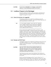
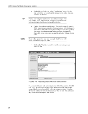
For the time series files, use a one hour file size and for you. • Finally, change the output file name. Practice converting the data from the card and processing it with a one day file size. The default output file name is TOB1_stationname.ts_data.dat, where stationname is the datalogger serial number. The factory default station name is the datalogger's station name and can be set using DevConfig.exe (part of...
For the time series files, use a one hour file size and for you. • Finally, change the output file name. Practice converting the data from the card and processing it with a one day file size. The default output file name is TOB1_stationname.ts_data.dat, where stationname is the datalogger serial number. The factory default station name is the datalogger's station name and can be set using DevConfig.exe (part of...

CSAT3 3-D Sonic Anemometer
Page 3
... CAMPBELL SCIENTIFIC, INC. Batteries, fine-wire thermocouples, desiccant, and other locations, Campbell will return such products by Campbell, and product specific training, is in lieu of removing, reinstalling, and shipping defective products to products manufactured by surface carrier prepaid within the continental United States of Campbell's product warranty. The warranty for installation services performed by Campbell such as programming to customer specifications, electrical connections to Campbell...
... CAMPBELL SCIENTIFIC, INC. Batteries, fine-wire thermocouples, desiccant, and other locations, Campbell will return such products by Campbell, and product specific training, is in lieu of removing, reinstalling, and shipping defective products to products manufactured by surface carrier prepaid within the continental United States of Campbell's product warranty. The warranty for installation services performed by Campbell such as programming to customer specifications, electrical connections to Campbell...

CSAT3 3-D Sonic Anemometer
Page 5
... Programming using SDM 19 i Table of Contents PDF viewers: These page numbers refer to specific sections. 1. Use the PDF reader bookmarks tab for links to the printed version of Sound 15 8. CSAT3 Outputs 11 6.1 SDM Output 11 6.1.1 CRBasic Dataloggers 12 6.1.2 EDLOG Dataloggers 12 6.1.3 CR9000 12 6.2 RS-232 Output 13 6.3 Analog Output 13 7. Specifications 1 2.1 Measurements 1 2.2 Output Signals 2 2.3 Physical Description 3 2.4 Power Requirements 4 3. Installation 5 4.1 Orientation 5 4.2 Mounting 6 4.3 Leveling 8 4.4 Fine Wire Thermocouple 8 5. General 1 2. Data...
... Programming using SDM 19 i Table of Contents PDF viewers: These page numbers refer to specific sections. 1. Use the PDF reader bookmarks tab for links to the printed version of Sound 15 8. CSAT3 Outputs 11 6.1 SDM Output 11 6.1.1 CRBasic Dataloggers 12 6.1.2 EDLOG Dataloggers 12 6.1.3 CR9000 12 6.2 RS-232 Output 13 6.3 Analog Output 13 7. Specifications 1 2.1 Measurements 1 2.2 Output Signals 2 2.3 Physical Description 3 2.4 Power Requirements 4 3. Installation 5 4.1 Orientation 5 4.2 Mounting 6 4.3 Leveling 8 4.4 Fine Wire Thermocouple 8 5. General 1 2. Data...

CSAT3 3-D Sonic Anemometer
Page 17
... when using wire short haul modems. Spark gap protection is not needed with fiber optic short haul modems. TABLE 5-1. NOTE Before extending the SDM signal cable, read Appendix D. CSAT3 Power Battery Terminal Description Color Pin Positive 12 Vdc Red A Negative Power Reference Black B TABLE 5-2. CSAT3 SDM Output to a CR1000, CR800/850, CR23X and CR10(X) Datalogger Channel C1 C2 C3 G G Description SDM Data SDM Clock SDM Enable Digital...
... when using wire short haul modems. Spark gap protection is not needed with fiber optic short haul modems. TABLE 5-1. NOTE Before extending the SDM signal cable, read Appendix D. CSAT3 Power Battery Terminal Description Color Pin Positive 12 Vdc Red A Negative Power Reference Black B TABLE 5-2. CSAT3 SDM Output to a CR1000, CR800/850, CR23X and CR10(X) Datalogger Channel C1 C2 C3 G G Description SDM Data SDM Clock SDM Enable Digital...
CSAT3 3-D Sonic Anemometer
Page 20
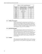
... CSAT3. With a 21X, single ended analog input channel 1 (labeled 1H) and a 10 K resistor is used in conjunction with the CSAT3 over the SDM bus. 6.1.2 EDLOG Dataloggers SDM is a Campbell Scientific communication protocol used to communicate with the CSAT3 over the SDM bus. 12 The EDLOG datalogger instruction, SDM-CSAT3 (P107), is achieved via the 9 pin CSI serial I/O port on the 9080 peripheral and memory card. CSAT3...
... CSAT3. With a 21X, single ended analog input channel 1 (labeled 1H) and a 10 K resistor is used in conjunction with the CSAT3 over the SDM bus. 6.1.2 EDLOG Dataloggers SDM is a Campbell Scientific communication protocol used to communicate with the CSAT3 over the SDM bus. 12 The EDLOG datalogger instruction, SDM-CSAT3 (P107), is achieved via the 9 pin CSI serial I/O port on the 9080 peripheral and memory card. CSAT3...

CSAT3 3-D Sonic Anemometer
Page 21
... outputs are changed using the PC's and CSAT3's RS-232 serial port. A copy of the CSAT3 PC software is available from the Campbell Scientific web site in the Support|Downloads section. 6.3 Analog Output The anemometer can be programmed to output four analog signals that the CSAT3 analog outputs also have two output ranges, low range (±32.768 m s-1) and high range (±65.536 m s-1). This software is enabled using the Windows CSAT3 PC support software (CSAT32.EXE) using the support software...
... outputs are changed using the PC's and CSAT3's RS-232 serial port. A copy of the CSAT3 PC software is available from the Campbell Scientific web site in the Support|Downloads section. 6.3 Analog Output The anemometer can be programmed to output four analog signals that the CSAT3 analog outputs also have two output ranges, low range (±32.768 m s-1) and high range (±65.536 m s-1). This software is enabled using the Windows CSAT3 PC support software (CSAT32.EXE) using the support software...

CSAT3 3-D Sonic Anemometer
Page 30
... example program in on the SDM bus are a counter. a CSAT3 ()/SDM-CSAT3 (P107) instruction with the "Set Execution Parameter" Command/Option. 61503, No Data Available. For example, when the anemometer is greater than 1, the number of the statistics based on -line, connect the CSAT3 to address an anemometer and the anemometer does not answer. The bits in units of sound, and...
... example program in on the SDM bus are a counter. a CSAT3 ()/SDM-CSAT3 (P107) instruction with the "Set Execution Parameter" Command/Option. 61503, No Data Available. For example, when the anemometer is greater than 1, the number of the statistics based on -line, connect the CSAT3 to address an anemometer and the anemometer does not answer. The bits in units of sound, and...
CSAT3 3-D Sonic Anemometer
Page 32
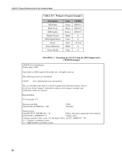
... coordinate system 24 Search 'for Program Example 1 Description SDM Data SDM Clock SDM Enable Digital Ground SDM Signal Shield Power Power Refernece Power Shield Color Green White Brown Black Clear Red Black Clear CR3000 SDM-C1 SDM-C2 SDM-C3 G G +12 Vdc G G EXAMPLE 1. Wiring for the text string "unique" to find the locations where unique constants and 'calibration values are measured: ' 'CSAT3 three dimensional...
... coordinate system 24 Search 'for Program Example 1 Description SDM Data SDM Clock SDM Enable Digital Ground SDM Signal Shield Power Power Refernece Power Shield Color Green White Brown Black Clear Red Black Clear CR3000 SDM-C1 SDM-C2 SDM-C3 G G +12 Vdc G G EXAMPLE 1. Wiring for the text string "unique" to find the locations where unique constants and 'calibration values are measured: ' 'CSAT3 three dimensional...
CSAT3 3-D Sonic Anemometer
Page 37
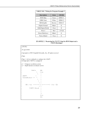
... (default) to configure the CSAT3. ;Set high after CSAT3 is configured. ;() -> Compass coordinate system ;{} -> Right handed coordinate system ; ; ; Transducers -> * | ; \ | ; \ | ; \ | ; (W) {-y y} (E) ; / | ; v ; {+x} ; (S) ; 29 theta (N) ; \ {-x} ; \ | ; CSAT3 Three Dimensional Sonic Anemometer TABLE 10-8. Measuring the CSAT3 Using the SDM Output and a CR23X Datalogger ;{CR23X} ; ;22 April 2001 ;Copyright (c) 2001 Campbell Scientific, Inc. Wiring for Program Example 2 Description SDM Data SDM Clock SDM Enable Digital Ground SDM Signal Shield Power...
... (default) to configure the CSAT3. ;Set high after CSAT3 is configured. ;() -> Compass coordinate system ;{} -> Right handed coordinate system ; ; ; Transducers -> * | ; \ | ; \ | ; \ | ; (W) {-y y} (E) ; / | ; v ; {+x} ; (S) ; 29 theta (N) ; \ {-x} ; \ | ; CSAT3 Three Dimensional Sonic Anemometer TABLE 10-8. Measuring the CSAT3 Using the SDM Output and a CR23X Datalogger ;{CR23X} ; ;22 April 2001 ;Copyright (c) 2001 Campbell Scientific, Inc. Wiring for Program Example 2 Description SDM Data SDM Clock SDM Enable Digital Ground SDM Signal Shield Power...
CSAT3 3-D Sonic Anemometer
Page 47
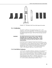
... and electronics. CSAT3s running embedded code version 3 will be suspect. This offset is 337 m s-1. 39 For the cold shifted calibration range, the offset is added by the CSAT3()/SDM-CSAT3 (P107) instruction Command/Option 90, 91, 98, and 99. P/N 28902 CSAT3 Sonic Wick Spares Kit contents 11.2 Calibration The CSAT3 is calibrated over the temperature range of sound. Doing so will set diagnostic flags, under...
... and electronics. CSAT3s running embedded code version 3 will be suspect. This offset is 337 m s-1. 39 For the cold shifted calibration range, the offset is added by the CSAT3()/SDM-CSAT3 (P107) instruction Command/Option 90, 91, 98, and 99. P/N 28902 CSAT3 Sonic Wick Spares Kit contents 11.2 Calibration The CSAT3 is calibrated over the temperature range of sound. Doing so will set diagnostic flags, under...
CSAT3 3-D Sonic Anemometer
Page 52
... powering the RS-232 drivers allows the use of the electronics box lid. Save RAM contents, with the large Phillips screw driver. The Campbell Scientific logo is in the Long Status Message. The processor is a movable jumper connecting the center pin and the right pin. where n = 0 means power the RS-232 drivers if RTS is in the normal operate mode. "sr2718" - Remove all external connectors...
... powering the RS-232 drivers allows the use of the electronics box lid. Save RAM contents, with the large Phillips screw driver. The Campbell Scientific logo is in the Long Status Message. The processor is a movable jumper connecting the center pin and the right pin. where n = 0 means power the RS-232 drivers if RTS is in the normal operate mode. "sr2718" - Remove all external connectors...

CSAT3 3-D Sonic Anemometer
Page 67
... rate down using Instruction SDMSpeed () (CRBasic dataloggers) or Set SDM Clock (P108 for a 21X and P115 for the CRBasic dataloggers or a parameter between 1 and 255, where 1 is the fastest SDM clock rate and 255 is having problems communicating with the CSAT3. The EDLOG dataloggers output three arrays. Test the new SDM clock rate in the Support|Downloads section. This...
... rate down using Instruction SDMSpeed () (CRBasic dataloggers) or Set SDM Clock (P108 for a 21X and P115 for the CRBasic dataloggers or a parameter between 1 and 255, where 1 is the fastest SDM clock rate and 255 is having problems communicating with the CSAT3. The EDLOG dataloggers output three arrays. Test the new SDM clock rate in the Support|Downloads section. This...
