
Instruction Manual - English
Page 1
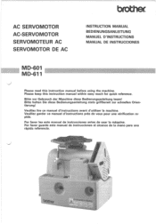
... d'instructions avant d'utiliser la machine. II 1 11 ' 11 .1, I I: I lo ig% Por favor guarde este manual de instrucciones al alcance de la mano para una rapida referencia. Veuillez garder ce manuel d'instructions pres de vous pour une verification rapide. AC SERVOMOTOR AC-SERVOMOTOR SERVOMOTEUR AC SERVOMOTOR DE AC INSTRUCTION MANUAL BEDIENUNGSANLEITUNG MANUEL D'INSTRUCTIONS MANUAL DE INSTRUCCIONES MD-601 MD-611 Please read this instruction manual within easy reach for quick...
... d'instructions avant d'utiliser la machine. II 1 11 ' 11 .1, I I: I lo ig% Por favor guarde este manual de instrucciones al alcance de la mano para una rapida referencia. Veuillez garder ce manuel d'instructions pres de vous pour une verification rapide. AC SERVOMOTOR AC-SERVOMOTOR SERVOMOTEUR AC SERVOMOTOR DE AC INSTRUCTION MANUAL BEDIENUNGSANLEITUNG MANUEL D'INSTRUCTIONS MANUAL DE INSTRUCCIONES MD-601 MD-611 Please read this instruction manual within easy reach for quick...

Instruction Manual - English
Page 3
...user. Las instrucciones a continuation de esta indication representan situaciones en las cuales el no respetar las instrucciones al usar el motor posiblemente puede resultar en heridas moderadas a leves o darios. - Die in slight to moderate injury to observe the instructions which appear after this manual...to observe the instructions which appear after this indication while using the motor could possibly result in dieser Bedienungsanleitung verwendeten Ausdriicke and ihre Bedeutung sind nachstehend aufgefuhrt. Si l'on ne respecte pas les instructions mentionnees apres ...
...user. Las instrucciones a continuation de esta indication representan situaciones en las cuales el no respetar las instrucciones al usar el motor posiblemente puede resultar en heridas moderadas a leves o darios. - Die in slight to moderate injury to observe the instructions which appear after this manual...to observe the instructions which appear after this indication while using the motor could possibly result in dieser Bedienungsanleitung verwendeten Ausdriicke and ihre Bedeutung sind nachstehend aufgefuhrt. Si l'on ne respecte pas les instructions mentionnees apres ...
Instruction Manual - English
Page 4
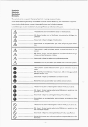
...muR. Ce symbole indique qu'il faut faire la connexion de terre. This symbol is used to indicate general actions which are used in dieser Bedienungsanleitung verwendeten Symbole and ihre Bedeutung sind nachstehend aufgefiihrt. Ce symbole indique les actions generales qu... Los simbolos que se usan en este manual y sus significados se indican a continuaci6n. IS ) (S ) ® This symbol is used to indicate that should be made. Este simbolo se usa para indicar que existe peligro de golpes electricos. Este simbolo se usa para indicar que se debe tener cuidado en ...
...muR. Ce symbole indique qu'il faut faire la connexion de terre. This symbol is used to indicate general actions which are used in dieser Bedienungsanleitung verwendeten Symbole and ihre Bedeutung sind nachstehend aufgefiihrt. Ce symbole indique les actions generales qu... Los simbolos que se usan en este manual y sus significados se indican a continuaci6n. IS ) (S ) ® This symbol is used to indicate that should be made. Este simbolo se usa para indicar que existe peligro de golpes electricos. Este simbolo se usa para indicar que se debe tener cuidado en ...
Instruction Manual - English
Page 5
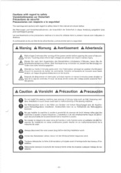
... Fehlbetrieb der Nahmaschine kommen. Certains composants se trouvant sous haute tension, on risque de graves blessures si on les touche. A Caution A Vorsicht A Precaution A Precaucion Do not install the sewing machine near sources of the control box. No instalar la maquina de coser cerca de fuentes e ruido fuertes como un soldador de alta frecuencia. Immer den Netzstecker ziehen, bevor...
... Fehlbetrieb der Nahmaschine kommen. Certains composants se trouvant sous haute tension, on risque de graves blessures si on les touche. A Caution A Vorsicht A Precaution A Precaucion Do not install the sewing machine near sources of the control box. No instalar la maquina de coser cerca de fuentes e ruido fuertes como un soldador de alta frecuencia. Immer den Netzstecker ziehen, bevor...
Instruction Manual - English
Page 24
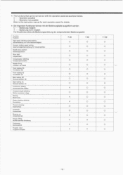
... Forward tacking speed setting Geschwindigkeitseinstellung fur Vorwartsheften Needle stop position Nadelstopposition Slow start Langsamstart Compensation stitching Kompensationsstiche Needle lifting Anheben der Nadel Front tacking (N) Frontheften (N) Front tacking (V) Frontheften (V) Back tacking (N) Ruckwartsheften (N) Back tacking (V) Ruckwartsheften (V) Continuous tacking Kontinuierliches Heften Constant length stitching Stiche konstanter Lange Naming Benennung Pleats pressing stitching Druckstiche Thread trimming Fadenschere Automatic Automatisch Reverse run Umkehrbetrieb Presser lifting...
... Forward tacking speed setting Geschwindigkeitseinstellung fur Vorwartsheften Needle stop position Nadelstopposition Slow start Langsamstart Compensation stitching Kompensationsstiche Needle lifting Anheben der Nadel Front tacking (N) Frontheften (N) Front tacking (V) Frontheften (V) Back tacking (N) Ruckwartsheften (N) Back tacking (V) Ruckwartsheften (V) Continuous tacking Kontinuierliches Heften Constant length stitching Stiche konstanter Lange Naming Benennung Pleats pressing stitching Druckstiche Thread trimming Fadenschere Automatic Automatisch Reverse run Umkehrbetrieb Presser lifting...
Instruction Manual - English
Page 32
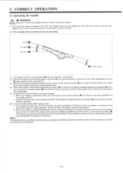
... stages. If it to the neutral position 0, the machine will stop above the needle plate. (5) If using the knee switch. Note: The presser foot can also be lowered using with the synchronizer cord disconnected * When the treadle is carried out. CORRECT OPERATION 3.1 Operating the treadle A A Caution Take your foot off the treadle before turning on to position 0, low-speed sewing is pressed forward and then back...
... stages. If it to the neutral position 0, the machine will stop above the needle plate. (5) If using the knee switch. Note: The presser foot can also be lowered using with the synchronizer cord disconnected * When the treadle is carried out. CORRECT OPERATION 3.1 Operating the treadle A A Caution Take your foot off the treadle before turning on to position 0, low-speed sewing is pressed forward and then back...
Instruction Manual - English
Page 36
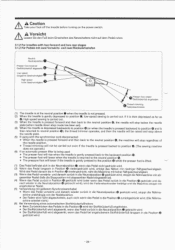
... treadles with the synchronizer cord disconnected * When the needle is pressed forward and then back to the neutral position 0, the machine will stop regardless of the needle position. * Thread trimming will not be carried out even if the treadle is pressed backed to position 0. (The sewing machine does not operate.) (6) If an automatic presser lifter is being used * The presser foot will rise when the treadle...
... treadles with the synchronizer cord disconnected * When the needle is pressed forward and then back to the neutral position 0, the machine will stop regardless of the needle position. * Thread trimming will not be carried out even if the treadle is pressed backed to position 0. (The sewing machine does not operate.) (6) If an automatic presser lifter is being used * The presser foot will rise when the treadle...
Instruction Manual - English
Page 42
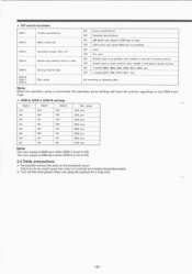
...-8 Sewing machine type Max. speed ON Export specifications -- speed 1000 spm 2000 spm 2500 spm 3000 spm 3500 spm 4000 spm 4500 spm 4700 spm Note: The max. The max. * DIP switch functions DSW-1 Treadle specifications DSW-2 Motor pulley size DSW-3 Automatic presser lifter unit DSW-4 Needle stop position (Refer to overheat and create a hazardous state. * Turn off the main power when not using the...
...-8 Sewing machine type Max. speed ON Export specifications -- speed 1000 spm 2000 spm 2500 spm 3000 spm 3500 spm 4000 spm 4500 spm 4700 spm Note: The max. The max. * DIP switch functions DSW-1 Treadle specifications DSW-2 Motor pulley size DSW-3 Automatic presser lifter unit DSW-4 Needle stop position (Refer to overheat and create a hazardous state. * Turn off the main power when not using the...
Instruction Manual - English
Page 46
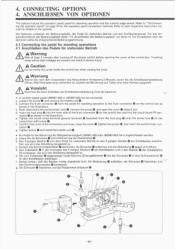
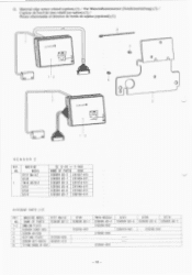
... hohe Verletzungsgefahr. Connect the 9-pin connector 0 from the foot plug 0 onto the screw hole 0 on page 10 for standing operations 4.1 AnschlieBen des Pedals fur stehenden Betrieb A Warning Wait at least 3 minutes after turning off the power switch before opening the cover of the 9-pin connector 0 on the control box as shown in der Abbildung dargestellt ist. Insert the foot plug 0 into the circuit...
... hohe Verletzungsgefahr. Connect the 9-pin connector 0 from the foot plug 0 onto the screw hole 0 on page 10 for standing operations 4.1 AnschlieBen des Pedals fur stehenden Betrieb A Warning Wait at least 3 minutes after turning off the power switch before opening the cover of the 9-pin connector 0 on the control box as shown in der Abbildung dargestellt ist. Insert the foot plug 0 into the circuit...
Instruction Manual - English
Page 48
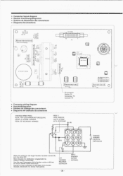
... conectores 0 •••41 1411- O1:1OOOO -666n 6666-6-i 1:1 0000000 226-11N PA 0 111 * Connector wiring diagram * Anschluildiagramm * Schema de cablage des connecteurs * Diagrama del cableado de conectores VARIABLE-SPEED PEDAL PEDAL FOR GESCHWINDIGKEITSREGELUNG PEDALE A VITESSE VARIABLE PEDAL DE VELOCIDAD VARIABLE HIGH. Wenn Schulter fur Zielfunktion eingeschaltet ist, anderen Schalter einschalten. LIFT ANHEBEN RELEVEUR ELEVACION...
... conectores 0 •••41 1411- O1:1OOOO -666n 6666-6-i 1:1 0000000 226-11N PA 0 111 * Connector wiring diagram * Anschluildiagramm * Schema de cablage des connecteurs * Diagrama del cableado de conectores VARIABLE-SPEED PEDAL PEDAL FOR GESCHWINDIGKEITSREGELUNG PEDALE A VITESSE VARIABLE PEDAL DE VELOCIDAD VARIABLE HIGH. Wenn Schulter fur Zielfunktion eingeschaltet ist, anderen Schalter einschalten. LIFT ANHEBEN RELEVEUR ELEVACION...

Instruction Manual - English
Page 59
NAGOYA, JAPAN Printed in Japan, 1996, 3 J90025-001 On BROTHER INDUSTRIES, LTD.
NAGOYA, JAPAN Printed in Japan, 1996, 3 J90025-001 On BROTHER INDUSTRIES, LTD.
Parts Manual - English
Page 5
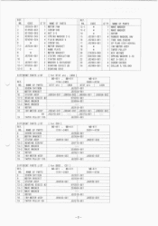
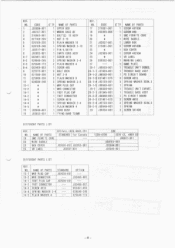
...TAPER PULLEY 105 J02281-001 DIFFERENT PARTS LIST REF. CODE Q'TY NAME OF PARTS 1 J02525-001 1 MOTOR FAN 2 014500-632 1 SCREW 5X6 3 021500-205 4 NUT 2-5 4 028050-245 4 SPRING WASHER 2-5 5 025050-335 4 PLAIN WASHER 5 6 * 4 SCREW 5XL 7-1 J02534-001 1 MOTOR BRACKET 7-2 --- 1 NAME PLATE 8 * 1 MOTOR BRACKET 9 J02536-001 2 ...-002 J02281-001 MD-611 380V--415V J80657-002 J80653-002 DIFFERENT PARTS LIST ( for 8131 etc LOCK ) MD-601 , MD-611 MD-611 REF. 110V--240V 380V--415V NO. NO. NAME OF PARTS 1 10V--240V 6 SCREW 5X115DB J02537-001 8 MOTOR BRACKET J02534-001 ...
...TAPER PULLEY 105 J02281-001 DIFFERENT PARTS LIST REF. CODE Q'TY NAME OF PARTS 1 J02525-001 1 MOTOR FAN 2 014500-632 1 SCREW 5X6 3 021500-205 4 NUT 2-5 4 028050-245 4 SPRING WASHER 2-5 5 025050-335 4 PLAIN WASHER 5 6 * 4 SCREW 5XL 7-1 J02534-001 1 MOTOR BRACKET 7-2 --- 1 NAME PLATE 8 * 1 MOTOR BRACKET 9 J02536-001 2 ...-002 J02281-001 MD-611 380V--415V J80657-002 J80653-002 DIFFERENT PARTS LIST ( for 8131 etc LOCK ) MD-601 , MD-611 MD-611 REF. 110V--240V 380V--415V NO. NO. NAME OF PARTS 1 10V--240V 6 SCREW 5X115DB J02537-001 8 MOTOR BRACKET J02534-001 ...
Parts Manual - English
Page 7
.... LOCK , B883 , C51 ) REF. NO. CODE Q'TY NAME OF PARTS 7 J02293-001 1 FINGER GUARD 8 J00351-001 1 BELT CLAMP PLATE 2 9 J02508-001 1 D-CORD COVER 10 215082-001 1 SCREW 4X12DA 11 * 1 BELT COVER STOPPER DIFFERENT PARTS LIST ( for COV ) REF. DIFFERENT PARTS LIST ( for 8737 etc . CODE Q'TY NAME OF PARTS 1 J02513-001 1 MOTOR COVER 2 J00494-001 3 SCREW 4X14DA 3 J02515-001 1 BELT COVER 4 224508-001 5 SCREW 4X10DC 5 * 1 SCREW 4XL 6 J02516-001 1 BELT SUB COVER...
.... LOCK , B883 , C51 ) REF. NO. CODE Q'TY NAME OF PARTS 7 J02293-001 1 FINGER GUARD 8 J00351-001 1 BELT CLAMP PLATE 2 9 J02508-001 1 D-CORD COVER 10 215082-001 1 SCREW 4X12DA 11 * 1 BELT COVER STOPPER DIFFERENT PARTS LIST ( for COV ) REF. DIFFERENT PARTS LIST ( for 8737 etc . CODE Q'TY NAME OF PARTS 1 J02513-001 1 MOTOR COVER 2 J00494-001 3 SCREW 4X14DA 3 J02515-001 1 BELT COVER 4 224508-001 5 SCREW 4X10DC 5 * 1 SCREW 4XL 6 J02516-001 1 BELT SUB COVER...
Parts Manual - English
Page 9
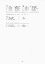
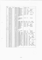
...MD-611 380V-415V J80690-001 MD-611 400V CE J80691-001 DIFFERENT PARTS LIST ( for 8737 etc , LOCK REF. NO. NAME OF PARTS ...PARTS LIST ( for COV ) REF. MD-601 MD-601 NO. J03040-001 26-2 NBN CONNECTOR --- -6- J02514-001 --- 0A4301-205 --- J03137-001 --- CODE 1 J02998-001 2 * 3 * 4 * 5 228295-001 6 * 7-1 * 1-2 * 8-1 * 8-2 * 9 * 10 * 11 * 12 229017-001 13 * 14 J02029-001 15 J01892-001 16 * O'TY NAME OF PARTS 1 UPPER BOX 1 TRANSFORMER 1 TYING BAND 2.2X85 2 SCREW 4XL 5 HOLDER KGLS-6S 1 IMP-ASSY 1 SCREW 4X14DA 2 SCREW 3X12DA 2 SCREW 4X1ODA 3 SCREW...
...MD-611 380V-415V J80690-001 MD-611 400V CE J80691-001 DIFFERENT PARTS LIST ( for 8737 etc , LOCK REF. NO. NAME OF PARTS ...PARTS LIST ( for COV ) REF. MD-601 MD-601 NO. J03040-001 26-2 NBN CONNECTOR --- -6- J02514-001 --- 0A4301-205 --- J03137-001 --- CODE 1 J02998-001 2 * 3 * 4 * 5 228295-001 6 * 7-1 * 1-2 * 8-1 * 8-2 * 9 * 10 * 11 * 12 229017-001 13 * 14 J02029-001 15 J01892-001 16 * O'TY NAME OF PARTS 1 UPPER BOX 1 TRANSFORMER 1 TYING BAND 2.2X85 2 SCREW 4XL 5 HOLDER KGLS-6S 1 IMP-ASSY 1 SCREW 4X14DA 2 SCREW 3X12DA 2 SCREW 4X1ODA 3 SCREW...
Parts Manual - English
Page 11
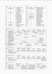
... EMC FERRITE CORE WIRE SADOLE LOWER BOX SCREW 4X1ODB BOX COVER SCREW 4X25DA VR LABEL WARNING LABEL NAME PLATE TREADLE UNIT DOMES. J02495-001 FOOT PLUG CAP J02039-001 --- SPRING SCREW 5X14DB DIFFERENT PARTS LIST REF. 8737etc,LOCK,B883,C51 NO. NO. 1 2 3 4 5 6 7 8 8-1 8-2 8-3 8-4 9 10 11 12 13-1 13-2 14-1 14-2 14-3 14-4 14-5 15 16 CODE J02998-001 J00107-001 210965-081 021...
... EMC FERRITE CORE WIRE SADOLE LOWER BOX SCREW 4X1ODB BOX COVER SCREW 4X25DA VR LABEL WARNING LABEL NAME PLATE TREADLE UNIT DOMES. J02495-001 FOOT PLUG CAP J02039-001 --- SPRING SCREW 5X14DB DIFFERENT PARTS LIST REF. 8737etc,LOCK,B883,C51 NO. NO. 1 2 3 4 5 6 7 8 8-1 8-2 8-3 8-4 9 10 11 12 13-1 13-2 14-1 14-2 14-3 14-4 14-5 15 16 CODE J02998-001 J00107-001 210965-081 021...
Parts Manual - English
Page 15
... OF PARTS 2PSWITCH ASSEMBLY#19-3 2PSWITCH ASSEMBLY#19-4 2PSWITCH ASSEMBLY#24 2PSWITCH ASSEMBLY#16-3 2PSWITCH ASSEMBLY#31-2 2PSWITCH ASSEMBLY#19-7 2PSWITCH ASSEMBLY#25 3P PLUG ASSEMBLY#10K32 3P PLUG ASSEMBLY#10-32 BUSSING STR13. 5 NUT SM13. 5 2PSWITCH ASSEMBLY#31K2 2PSWITCH ASSEMBLY#31-2 BUSSING STR13. 5 NUT SM13. 5 2PSWITCH ASSEMBLY IN#1-1 2PSWITCH ASSEMBLY IN#1-2 3PSWITCH ASSEMBLY#1 1-7 3PSWITCH ASSEMBLY#11-8 3PSWITCH ASSEMBLY#15 3PSWITCH ASSEMBLY#9-16 EMC BOX ASSEMBLY#3 4P PLUG ASSEMBLY#11K...
... OF PARTS 2PSWITCH ASSEMBLY#19-3 2PSWITCH ASSEMBLY#19-4 2PSWITCH ASSEMBLY#24 2PSWITCH ASSEMBLY#16-3 2PSWITCH ASSEMBLY#31-2 2PSWITCH ASSEMBLY#19-7 2PSWITCH ASSEMBLY#25 3P PLUG ASSEMBLY#10K32 3P PLUG ASSEMBLY#10-32 BUSSING STR13. 5 NUT SM13. 5 2PSWITCH ASSEMBLY#31K2 2PSWITCH ASSEMBLY#31-2 BUSSING STR13. 5 NUT SM13. 5 2PSWITCH ASSEMBLY IN#1-1 2PSWITCH ASSEMBLY IN#1-2 3PSWITCH ASSEMBLY#1 1-7 3PSWITCH ASSEMBLY#11-8 3PSWITCH ASSEMBLY#15 3PSWITCH ASSEMBLY#9-16 EMC BOX ASSEMBLY#3 4P PLUG ASSEMBLY#11K...
Parts Manual - English
Page 16
...PARTS CODE SENSOR #2-2 291657-013 SENSOR #2-1 291659-011 SENSOR #2-3 291674-011 SENSOR #2-4 291640-011 SENSOR #2-6 291642-011 SENSOR #2-7 388706-011 DIFFERENT PARTS LIST REF. MACHINE MODEL B737 Mark2 NO. B798 B774 SENSOR #2-6 SENSOR #2-7 233263-001 -13- MACHINE ... OF PARTS SENSOR #2-2 1-2 EMBLEM PLATE 1 SENSOR CORD ASS. 3 SCREW 4X12DA 2 SETTING PLATE 237043-002 5 SCREW 437-40X12 062681-212 8 TYING BAND N-108 8748 SENSOR #2-1 233263-001 TWIN NEEDLE SENSOR #2-3 233268-002 215082-002 233501-001 B791 SENSOR #2-4 233619-001 ----- G. MODEL B737 Mark2 8148 1 TWIN NEEDLE B791 B798...
...PARTS CODE SENSOR #2-2 291657-013 SENSOR #2-1 291659-011 SENSOR #2-3 291674-011 SENSOR #2-4 291640-011 SENSOR #2-6 291642-011 SENSOR #2-7 388706-011 DIFFERENT PARTS LIST REF. MACHINE MODEL B737 Mark2 NO. B798 B774 SENSOR #2-6 SENSOR #2-7 233263-001 -13- MACHINE ... OF PARTS SENSOR #2-2 1-2 EMBLEM PLATE 1 SENSOR CORD ASS. 3 SCREW 4X12DA 2 SETTING PLATE 237043-002 5 SCREW 437-40X12 062681-212 8 TYING BAND N-108 8748 SENSOR #2-1 233263-001 TWIN NEEDLE SENSOR #2-3 233268-002 215082-002 233501-001 B791 SENSOR #2-4 233619-001 ----- G. MODEL B737 Mark2 8148 1 TWIN NEEDLE B791 B798...
Parts Manual - English
Page 17
... 2 SPRING WASHER 2-3 18 025030-132 2 WASHER 3 19 233063-001 1 ALUMI SHEET 20 233500-001 1 CORD HOLDER 21 062670-612 1 SCREW 357-40X6 22 S02702-001 2 CORD HOLDER#U2 23 S02703-001 2 CORD HOLDER#U3 24 233545-001 1 SENSOR HOLDER#A REF. CODE G'TY NAME OF PARTS 25 233544-001 1 SENSOR SETTING PLATE#3 26 062680-812 2 SCREW 437-40X8 27 S02701-001 2 CORD HOLDER#U1 29 233604-001 1 CORD HOLDER...
... 2 SPRING WASHER 2-3 18 025030-132 2 WASHER 3 19 233063-001 1 ALUMI SHEET 20 233500-001 1 CORD HOLDER 21 062670-612 1 SCREW 357-40X6 22 S02702-001 2 CORD HOLDER#U2 23 S02703-001 2 CORD HOLDER#U3 24 233545-001 1 SENSOR HOLDER#A REF. CODE G'TY NAME OF PARTS 25 233544-001 1 SENSOR SETTING PLATE#3 26 062680-812 2 SCREW 437-40X8 27 S02701-001 2 CORD HOLDER#U1 29 233604-001 1 CORD HOLDER...
Parts Manual - English
Page 19
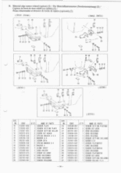
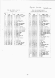
...(ITV 1 1 1 1 4 4 4 2 4 2 2 2 1 1 2 1 1 1 4 1 2 1 1 1 1 4 1 1 1 3 1 2 2 2 4 NAME OF PARTS PEDAL THREAD TRIM #6 PEDAL BASE ASSEMBLY#5 ARM CLAMP#L ARM CLAMP#R STUD SCREW 8X16. 1 SPRING WASHER 2-8 NUT 8 PEDAL CLAMP ASSEMBLY SPRING CUSHION#23 SCREW 4X12 SPRING L 2X12X57 RUBBER PLATE1. 6X5X45 RUBBER PLATE3.2X20X186 RUBBER PLATE3. 2X20X46 RUBBER PLATE3.2X20X15 PEDAL ASSEMBLY (SREED) PEDAL ASSEMBLY PRESSER SCREW 4X12D SCREW 4X4 PEDAL TRIMMER ASS.#2 SCREW 4X8DA SCREW 4X20 WASHER 4 TUBE T5X12 SPRING 8X30 NUT 4 SPEED CONTROLLER#6 SCREW 4X12 M. P BUSH PEDAL COVER#5 SCREW 4X6DA IDENTIFICATION LABEL TYING...
...(ITV 1 1 1 1 4 4 4 2 4 2 2 2 1 1 2 1 1 1 4 1 2 1 1 1 1 4 1 1 1 3 1 2 2 2 4 NAME OF PARTS PEDAL THREAD TRIM #6 PEDAL BASE ASSEMBLY#5 ARM CLAMP#L ARM CLAMP#R STUD SCREW 8X16. 1 SPRING WASHER 2-8 NUT 8 PEDAL CLAMP ASSEMBLY SPRING CUSHION#23 SCREW 4X12 SPRING L 2X12X57 RUBBER PLATE1. 6X5X45 RUBBER PLATE3.2X20X186 RUBBER PLATE3. 2X20X46 RUBBER PLATE3.2X20X15 PEDAL ASSEMBLY (SREED) PEDAL ASSEMBLY PRESSER SCREW 4X12D SCREW 4X4 PEDAL TRIMMER ASS.#2 SCREW 4X8DA SCREW 4X20 WASHER 4 TUBE T5X12 SPRING 8X30 NUT 4 SPEED CONTROLLER#6 SCREW 4X12 M. P BUSH PEDAL COVER#5 SCREW 4X6DA IDENTIFICATION LABEL TYING...

Parts Manual - English
Page 24
BROTHER INDUSTRIES, LTD. NAGOYA, JAPAN Printed in Japan, 1997, 3 J90045-001
BROTHER INDUSTRIES, LTD. NAGOYA, JAPAN Printed in Japan, 1997, 3 J90045-001


