
Service Manual
Page 3
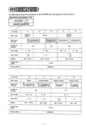
... 6.5 - 16 4 - 10 1- 2 (3) DP x 5 #16 Sub-class Main uses Decorative Stitching Number of stitches -1 -2 Ordinary clothes 1 i i i . , i I, i i i. i Denim 9,2:1( ( ;_.L ., r Knitted clothes . 1 i t t I .{ I 1 . - , , _rJ; ..„..,.--t----- O1 ' ! i k t 4. : t t it i t 4 i . CBROTHER INDUSTRIES, LTD:\ LK3-6430 MADE INpAPAN J [ Sub-class Main uses Decorative stitching Number of stitches Tack length Tack width Needle Presser foot stroke 1 -6 -7 ! The table below shows the...
... 6.5 - 16 4 - 10 1- 2 (3) DP x 5 #16 Sub-class Main uses Decorative Stitching Number of stitches -1 -2 Ordinary clothes 1 i i i . , i I, i i i. i Denim 9,2:1( ( ;_.L ., r Knitted clothes . 1 i t t I .{ I 1 . - , , _rJ; ..„..,.--t----- O1 ' ! i k t 4. : t t it i t 4 i . CBROTHER INDUSTRIES, LTD:\ LK3-6430 MADE INpAPAN J [ Sub-class Main uses Decorative stitching Number of stitches Tack length Tack width Needle Presser foot stroke 1 -6 -7 ! The table below shows the...
Service Manual
Page 4
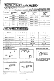
Measure distance from thread take-up lever. Start the machine, and measure as shown above . MOTOR :PUL AND Ic2Ta,hF3sere0eL0qoKufre3punm-scBiy.n4gW3I0chheHe(Snrimpgecmhwihci)SnaagnlptgesheipnredegeaBdtdha,ero1,ITpsapeecraketidne,g(MrtDheMoiefateaommrcrehtaPtoiecunrthle)lheineyisetacaabtple1a....is started to thread take -up spring tension Measure as shown above . Thread take-up lever stroke Start the machine and measure distance from lever position when machine is lower to thread take -up spring height 4lj kir+ . Thread take -up spring to its stop ...
Measure distance from thread take-up lever. Start the machine, and measure as shown above . MOTOR :PUL AND Ic2Ta,hF3sere0eL0qoKufre3punm-scBiy.n4gW3I0chheHe(Snrimpgecmhwihci)SnaagnlptgesheipnredegeaBdtdha,ero1,ITpsapeecraketidne,g(MrtDheMoiefateaommrcrehtaPtoiecunrthle)lheineyisetacaabtple1a....is started to thread take -up spring tension Measure as shown above . Thread take-up lever stroke Start the machine and measure distance from lever position when machine is lower to thread take -up spring height 4lj kir+ . Thread take -up spring to its stop ...
Service Manual
Page 6
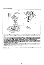
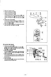
... stitch at low speed from roller holder® to the upper shaft. 2. CLUTCH MECHANISM 0 0 0 0 0 -- speed part 0 of clutch cam -4- This makes the machine sew up on the high speed part © low speed, roller of clutch cam0,and then moves onto gets into a recess of clutch cam This...drive clutch cam lever 0 about clutch actuating lever shaft 0 so that roller holderID comes under roller O. the low speed part ®. As the machine sews 4 stitches at its end goes up on the low ®. I. One end of feed cam roller® is connected toclutch lever0,and the...
... stitch at low speed from roller holder® to the upper shaft. 2. CLUTCH MECHANISM 0 0 0 0 0 -- speed part 0 of clutch cam -4- This makes the machine sew up on the high speed part © low speed, roller of clutch cam0,and then moves onto gets into a recess of clutch cam This...drive clutch cam lever 0 about clutch actuating lever shaft 0 so that roller holderID comes under roller O. the low speed part ®. As the machine sews 4 stitches at its end goes up on the low ®. I. One end of feed cam roller® is connected toclutch lever0,and the...
Service Manual
Page 10
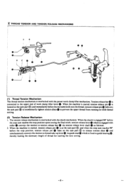
...lever via tension release lever shaft 0 as fulcrum. 2. tension release pin 0 rides on while thread cutting. (2) Tension Release Mechanism I. When the machine is started tension release pin 0 is connected to tension release bar 0 via guide stud which is at the cam part 0; When the clutch ...is located at the cam part O: and when the stop position. and immediately before the stop cam reaches 90° ® ®. When the machine is started , tension release pin 0 is engaged with roller 0 conveys the motion to the upper end of thread for starting the next sewing. 0...
...lever via tension release lever shaft 0 as fulcrum. 2. tension release pin 0 rides on while thread cutting. (2) Tension Release Mechanism I. When the machine is started tension release pin 0 is connected to tension release bar 0 via guide stud which is at the cam part 0; When the clutch ...is located at the cam part O: and when the stop position. and immediately before the stop cam reaches 90° ® ®. When the machine is started , tension release pin 0 is engaged with roller 0 conveys the motion to the upper end of thread for starting the next sewing. 0...
Service Manual
Page 11
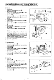
... ® by loosening four screws 6. Side cover Remove side cover ® by loosening six screws ® 5. drive leveret there. Raise the machine head. and remove the V-belt. 9. Return the machine head. 10. and then needle bar thread guide 2. Needle plate 0 by hand until the bolt comes to the right and left . 3. C O- needle...
... ® by loosening four screws 6. Side cover Remove side cover ® by loosening six screws ® 5. drive leveret there. Raise the machine head. and remove the V-belt. 9. Return the machine head. 10. and then needle bar thread guide 2. Needle plate 0 by hand until the bolt comes to the right and left . 3. C O- needle...

Service Manual
Page 12
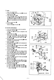
... screw 0 and washer 0, and then power pulley O. 2. r e oeeese O®0 09 • 9 1 0 0 -10- Guide stud 0 Remove it by turning it from pin O. 3. Power pulley With the machine at the stop ring and washer 0, and then ®, • power cam together with a screwdriver. ®, 5. Power cam 0 (I . Ei POWER WORK CLAMP LIFTER I . Also remove...
... screw 0 and washer 0, and then power pulley O. 2. r e oeeese O®0 09 • 9 1 0 0 -10- Guide stud 0 Remove it by turning it from pin O. 3. Power pulley With the machine at the stop ring and washer 0, and then ®, • power cam together with a screwdriver. ®, 5. Power cam 0 (I . Ei POWER WORK CLAMP LIFTER I . Also remove...
Service Manual
Page 13
...turning crank rod is hooked to the level position. 2. and remove tack length feed lever 0 by moving it . Lower the machine head to the spring hook. 5. and then roller holder cover 0. Brake assembly (D Loosen screw and remove brake assembly together with... remove emergency stop lever 0 after removing roller holder cover 0. 4. Temporarily install emergency stop lever O. 3. Clutch spring Disengage only the end of the machine. 0. 9. Brake spring Disengage brake spring 0 from the spring hook. 6. Clutch actuating lever 0 Remove nut (r) and screw and then clutch actuating ...
...turning crank rod is hooked to the level position. 2. and remove tack length feed lever 0 by moving it . Lower the machine head to the spring hook. 5. and then roller holder cover 0. Brake assembly (D Loosen screw and remove brake assembly together with... remove emergency stop lever 0 after removing roller holder cover 0. 4. Temporarily install emergency stop lever O. 3. Clutch spring Disengage only the end of the machine. 0. 9. Brake spring Disengage brake spring 0 from the spring hook. 6. Clutch actuating lever 0 Remove nut (r) and screw and then clutch actuating ...
Service Manual
Page 14
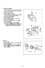
... holder 0. 2. clutch plate 0, key 0, washers 0. Knife cam lever 0 (1) Loosen screw 0. and then pulley assembly 0. Lower the machine head to the level position. 6. and remove stud 0. (2) Remove oil cap 0, loosen screw 0, pull out 0. Raise the machine head. 3. and remove knife cam lever 0 together with connecting rod PULLEY 1. Pulley assembly €0 Remove nut 0 (left...
... holder 0. 2. clutch plate 0, key 0, washers 0. Knife cam lever 0 (1) Loosen screw 0. and then pulley assembly 0. Lower the machine head to the level position. 6. and remove stud 0. (2) Remove oil cap 0, loosen screw 0, pull out 0. Raise the machine head. 3. and remove knife cam lever 0 together with connecting rod PULLEY 1. Pulley assembly €0 Remove nut 0 (left...
Service Manual
Page 15
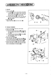
... (left-handed). 2. and temporarily tighten screw 0. (3) Put oil cap 0 on the periphery of knife cam lever 0. 4. fit three washers 0 onto the upper shaft. Return the machine head onto the oil pan. 2. and tighten knife cam lever shaft 0 with screw 0. (2) Connect thread trimming link 0 with the key. Operate knife cam lever 0 in...
... (left-handed). 2. and temporarily tighten screw 0. (3) Put oil cap 0 on the periphery of knife cam lever 0. 4. fit three washers 0 onto the upper shaft. Return the machine head onto the oil pan. 2. and tighten knife cam lever shaft 0 with screw 0. (2) Connect thread trimming link 0 with the key. Operate knife cam lever 0 in...
Service Manual
Page 16
...; 17 0 00 0 -14- 5. Move movable knife until its tip meets the needle plate mark 0, and tighten screw 0. • - 0 • - and snap stop cam. 4. Raise the machine head. 6. Brake spring 0 Hook brake spring to spring hook 0. 2.
...; 17 0 00 0 -14- 5. Move movable knife until its tip meets the needle plate mark 0, and tighten screw 0. • - 0 • - and snap stop cam. 4. Raise the machine head. 6. Brake spring 0 Hook brake spring to spring hook 0. 2.
Service Manual
Page 17
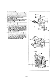
and connect its tip to the low speed part of the machine by turning the pulley. 6. Check that there is shifted to the left until clutch cam lever roller rides on the low speed part of clutch ...
and connect its tip to the low speed part of the machine by turning the pulley. 6. Check that there is shifted to the left until clutch cam lever roller rides on the low speed part of clutch ...
Service Manual
Page 18
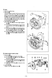
Raise the machine head. 2. move cam lever 0 so that the mark ® of the feed cam meets the mark 0 of the feed cam. 3. Feed cam 0 With the stopper ...
Raise the machine head. 2. move cam lever 0 so that the mark ® of the feed cam meets the mark 0 of the feed cam. 3. Feed cam 0 With the stopper ...
Service Manual
Page 20
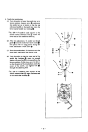
... lower end of the needle, and tighten bolt (111 through the adjusting hole. * If a DP X 17 needle is used , adjust it with screw S. - - (3) Raise the machine head. insert needle 0 into place with its lowest position. reference line 0 on the needle bar meets the lower end of the needle bar bushings. - 18...
... lower end of the needle, and tighten bolt (111 through the adjusting hole. * If a DP X 17 needle is used , adjust it with screw S. - - (3) Raise the machine head. insert needle 0 into place with its lowest position. reference line 0 on the needle bar meets the lower end of the needle bar bushings. - 18...
Service Manual
Page 22
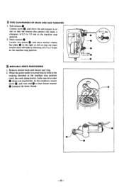
... shuttle race ring. 2. loosen screw O. and turn stud Q so that the main tension discs will make a clearance of 0.5 to 1.0 mm at the machine stop position. I . M MOVABLE KNIFE POSITIONING I . When the power pulley is turned little by little in or out so that the tension disc presser will ... AND SUB TENSIONS ©. and move the sub-tension in the rotating direction at the machine stop position. 2. Sub-tension Loosen screw and move tension release bar plate Q to 1.0 mm at the machine stop position (with the work clamp down), knife cam lever claw drops one step further....
... shuttle race ring. 2. loosen screw O. and turn stud Q so that the main tension discs will make a clearance of 0.5 to 1.0 mm at the machine stop position. I . M MOVABLE KNIFE POSITIONING I . When the power pulley is turned little by little in or out so that the tension disc presser will ... AND SUB TENSIONS ©. and move the sub-tension in the rotating direction at the machine stop position. 2. Sub-tension Loosen screw and move tension release bar plate Q to 1.0 mm at the machine stop position (with the work clamp down), knife cam lever claw drops one step further....
Service Manual
Page 26
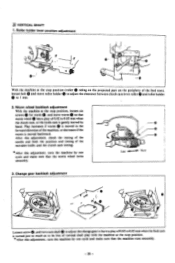
Change gear backlash adjustment et Loosen screw 0, and turn cam shaft Q to adjust the change gear to have a play with the machine at the stop position. * After this adjustment. loosen six screws 0 for worm 0. check the timing of the needle and feed: the position and timing of ... a play of 0.02 to 0.05 mm when the clutch cam, or the knife cam is turned just so much as to be free of the machine, or decreases if the worm is moved backward. and move roller holder 0 to adjust the clearance between clutch cam lever roller() and roller holder 0 to...
Change gear backlash adjustment et Loosen screw 0, and turn cam shaft Q to adjust the change gear to have a play with the machine at the stop position. * After this adjustment. loosen six screws 0 for worm 0. check the timing of the needle and feed: the position and timing of ... a play of 0.02 to 0.05 mm when the clutch cam, or the knife cam is turned just so much as to be free of the machine, or decreases if the worm is moved backward. and move roller holder 0 to adjust the clearance between clutch cam lever roller() and roller holder 0 to...
Service Manual
Page 27
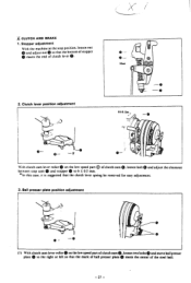
Stopper adjustment With the machine at the stop cam 0 and stopper to the right or left so that the clutch lever spring be removed for easy adjustment. 3. Meet 0 O O 2. With clutch ...
Stopper adjustment With the machine at the stop cam 0 and stopper to the right or left so that the clutch lever spring be removed for easy adjustment. 3. Meet 0 O O 2. With clutch ...
Service Manual
Page 28
...nut to such an extent hand, and that roller shaft 0 disengages from start lever ® when stop cam 0 reaches 5 mm before the machine stop cam is turned in the rotating direction. 5. after years of use, the pulley slips even after the above-mentioned adjustment, refer to meet the... presser plate 0 to the pulley disassembly instructions on Page 12, remove one washer, and make sure that stopper 0 contacts stop cam 90° before the machine stop position. - 28 - Start lever position adjustment 0-- -0 Loosen nut 0 and turn clutch cam so that the high speed pulley will not slip. ...
...nut to such an extent hand, and that roller shaft 0 disengages from start lever ® when stop cam 0 reaches 5 mm before the machine stop cam is turned in the rotating direction. 5. after years of use, the pulley slips even after the above-mentioned adjustment, refer to meet the... presser plate 0 to the pulley disassembly instructions on Page 12, remove one washer, and make sure that stopper 0 contacts stop cam 90° before the machine stop position. - 28 - Start lever position adjustment 0-- -0 Loosen nut 0 and turn clutch cam so that the high speed pulley will not slip. ...
Service Manual
Page 29
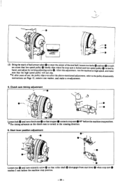
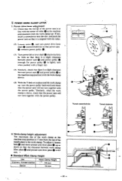
...mark of the ball presser plate meets the center of the power cam is depressed two steps. when stop cam Q reaches 90° before the machine stop cam 0. - 29 - Start stopper position adjustment Loosen two bolts and move start safe lever 6) up or do%%n so that . brake shoe ...contacts stop position. Brake adjustment Loosen screw 4) and turn brake actuating pin so ® that . %%hen the treadle is 3 mm at the machine stop position. e 7. Start safe lever adjustment Loosen two bolts 9 and move stoppers up or down so that the clearance between it and periphery of the...
...mark of the ball presser plate meets the center of the power cam is depressed two steps. when stop cam Q reaches 90° before the machine stop cam 0. - 29 - Start stopper position adjustment Loosen two bolts and move start safe lever 6) up or do%%n so that . brake shoe ...contacts stop position. Brake adjustment Loosen screw 4) and turn brake actuating pin so ® that . %%hen the treadle is 3 mm at the machine stop position. e 7. Start safe lever adjustment Loosen two bolts 9 and move stoppers up or down so that the clearance between it and periphery of the...
Service Manual
Page 30
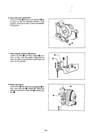
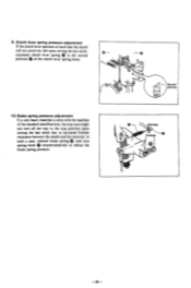
In such a case. Second position Decrease Increase C -30 - Brake spring pressure adjustment If a very heavy material is sewn with the machine of the standard specifications, the stop cam might not turn spring hook ID counterclockwise to reduce the brake spring pressure. unhook brake spring 0, and turn ...
In such a case. Second position Decrease Increase C -30 - Brake spring pressure adjustment If a very heavy material is sewn with the machine of the standard specifications, the stop cam might not turn spring hook ID counterclockwise to reduce the brake spring pressure. unhook brake spring 0, and turn ...
Service Manual
Page 31
... with a finger tip). (4) Similarly, check that the clearance between power cam 0 and power pulley 0 (enough for power pulley 0 to the work clamp at the machine stop position (with the power Similarly. Workvlamp height adjustment The maximum rise of the needle plate to lightly turn power drive lever shaft Q counterclockwise so... shaft 0 clockwise little by little so that there is down so that tiere is a slight clearance between power cam 0 and power pulley 0 at the machine stop position (with the work clamp down). (5) With the V-belt on in line with the center of roller 0 at the...
... with a finger tip). (4) Similarly, check that the clearance between power cam 0 and power pulley 0 (enough for power pulley 0 to the work clamp at the machine stop position (with the power Similarly. Workvlamp height adjustment The maximum rise of the needle plate to lightly turn power drive lever shaft Q counterclockwise so... shaft 0 clockwise little by little so that there is down so that tiere is a slight clearance between power cam 0 and power pulley 0 at the machine stop position (with the work clamp down). (5) With the V-belt on in line with the center of roller 0 at the...


