

Parts Manual - English
Page 4
... to changes in the "Assembly No." column indicates that the parts is a number in design without prior notice. Please, therefore, order by using this parts book 1. CONTENTS A. Upper shaft and needle bar mechanism C. Air pressure mechanism 17 4 S. Programmer device 19 7 Z. Feed mechanism (3) D. Work Clamp Lifter mechanism E. Threading mechanism J. Power supply equipment mechanism 16 3 R. Non-standard parts are subject to the different parts list (page 22.23). 2. Synchronizer N. Accessories (2) 20 9 Optional parts 21...
... to changes in the "Assembly No." column indicates that the parts is a number in design without prior notice. Please, therefore, order by using this parts book 1. CONTENTS A. Upper shaft and needle bar mechanism C. Air pressure mechanism 17 4 S. Programmer device 19 7 Z. Feed mechanism (3) D. Work Clamp Lifter mechanism E. Threading mechanism J. Power supply equipment mechanism 16 3 R. Non-standard parts are subject to the different parts list (page 22.23). 2. Synchronizer N. Accessories (2) 20 9 Optional parts 21...

Parts Manual - English
Page 27
... 43 44 41 5T 52 53 54 55 A t Name of Parts Accessory Bag Screw Driver 1 .1X52 Screw Driver 3.1X70 Screw Driver 5.5X118 Spanner 6X7 Scanner I X9 Spanner 10512 Mau Wrench (7inm) Allen Wrench (3mm) Abets Wrench (4mm) Men Wrench (5mm) Bobbin Needle Oiler Oil Tank %con 01 Spool Stand Assembly 1042 Column Foe Lower Pine (D) Set Screw (B) Washer 16 Nut 5/I Cap Rubber Washer Pipe Joint For...
... 43 44 41 5T 52 53 54 55 A t Name of Parts Accessory Bag Screw Driver 1 .1X52 Screw Driver 3.1X70 Screw Driver 5.5X118 Spanner 6X7 Scanner I X9 Spanner 10512 Mau Wrench (7inm) Allen Wrench (3mm) Abets Wrench (4mm) Men Wrench (5mm) Bobbin Needle Oiler Oil Tank %con 01 Spool Stand Assembly 1042 Column Foe Lower Pine (D) Set Screw (B) Washer 16 Nut 5/I Cap Rubber Washer Pipe Joint For...

Instruction Manual - English
Page 2
... number selection) to actual or enlarged size. Programming is thus completed much more precise positioning of applications. SUMMARY OF MODEL BAS-310 * Model BAS-310 is an automatic sewing machine with conventional pattern sewing machines. 4. All stitching operations are electronically controlled for fully automated sewing and finish of uses, Brother has incorporated into memory as has long been desired by conventional embroidery machines for precise pattern stitching in -house developed electronics technologies. The operator simply sets the work...
... number selection) to actual or enlarged size. Programming is thus completed much more precise positioning of applications. SUMMARY OF MODEL BAS-310 * Model BAS-310 is an automatic sewing machine with conventional pattern sewing machines. 4. All stitching operations are electronically controlled for fully automated sewing and finish of uses, Brother has incorporated into memory as has long been desired by conventional embroidery machines for precise pattern stitching in -house developed electronics technologies. The operator simply sets the work...

Instruction Manual - English
Page 3
... use 10 Adjusting of sewing SPEED control 10 Using the TEST switch 11 Using the emergency stop switch 11 Shifting a stitch pattern 12 _ItdAlN 0), 13 ((, STANDARD ADJUSTMENTS)) 14 E Needle bar height adjustment 14 E Needle bar lift stroke adjustment 14 0 Needle to shuttle hook point gap adjustment 14 E Shuttle driver needle contact adjustment 15 E Shuttle hook thread guide adjustment 15 LI Two-step work clamp adjustment 15 Movable knife adjustment 16 M Presser foot adjustment 17 E Changing the presser foot lift 17 Wiper adjustment 18 E E Needle and feed timing...
... use 10 Adjusting of sewing SPEED control 10 Using the TEST switch 11 Using the emergency stop switch 11 Shifting a stitch pattern 12 _ItdAlN 0), 13 ((, STANDARD ADJUSTMENTS)) 14 E Needle bar height adjustment 14 E Needle bar lift stroke adjustment 14 0 Needle to shuttle hook point gap adjustment 14 E Shuttle driver needle contact adjustment 15 E Shuttle hook thread guide adjustment 15 LI Two-step work clamp adjustment 15 Movable knife adjustment 16 M Presser foot adjustment 17 E Changing the presser foot lift 17 Wiper adjustment 18 E E Needle and feed timing...

Instruction Manual - English
Page 4
... misoperation realized with intermediate stop switch Presser lifter pedal Starting pedal Presser lifter pedal Starting pedal Operation panel Programmer Insert floppy disk here. Control box Power switch SPECIFICATIONS)) Stitch type Sewing machine Stitch length and max. sewing speed Feed format Max. MAIN PART NAMES Presser foot Work clamp Feed plate 4 0 Floppy disk Emergency stop function and safety circuits. 1200W x 590D x 1140H mm (Sitting) - 1350 H mm (Standing) T-shaped for use with low speed drive Automatic stop function for use sitting or standing Floppy disks...
... misoperation realized with intermediate stop switch Presser lifter pedal Starting pedal Presser lifter pedal Starting pedal Operation panel Programmer Insert floppy disk here. Control box Power switch SPECIFICATIONS)) Stitch type Sewing machine Stitch length and max. sewing speed Feed format Max. MAIN PART NAMES Presser foot Work clamp Feed plate 4 0 Floppy disk Emergency stop function and safety circuits. 1200W x 590D x 1140H mm (Sitting) - 1350 H mm (Standing) T-shaped for use with low speed drive Automatic stop function for use sitting or standing Floppy disks...
Instruction Manual - English
Page 5
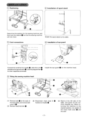
... back of the work table, and remove belt cover D Q. (2) Remove head lock bolt 0. (3) Disconnect chain hook S 0 hooked on the machine head. For pneumatic pedal Installation of the rotary hook cover 0 and the cord. When returning the machine to the table. [1] Cord connections 4. Install the spool stand to the original position, be careful of eye guard iii 0 Connect the cords for the sewing machine, and then lock the casters 0 so that the sewing machine will not move...
... back of the work table, and remove belt cover D Q. (2) Remove head lock bolt 0. (3) Disconnect chain hook S 0 hooked on the machine head. For pneumatic pedal Installation of the rotary hook cover 0 and the cord. When returning the machine to the table. [1] Cord connections 4. Install the spool stand to the original position, be careful of eye guard iii 0 Connect the cords for the sewing machine, and then lock the casters 0 so that the sewing machine will not move...

Instruction Manual - English
Page 7
Upper thread threading * Thread the upper thread as shown in the diagrams below. < With cotton thread > *49 0 Ic < With synthetic thread > 6 Bobbin thread winding Press° to (1) Slide the bobbin 0 all the way onto the spindle. (2) Thread the thread as shown in the figures, and wind the thread around the bobbin 0 several times in the direction of the arrow. Fully insert the needle 0 with the groove facing the front, and then retighten set screw 0. (CORRECT OPERATION El Needle installation 0 * Loosen set screw 0.
Upper thread threading * Thread the upper thread as shown in the diagrams below. < With cotton thread > *49 0 Ic < With synthetic thread > 6 Bobbin thread winding Press° to (1) Slide the bobbin 0 all the way onto the spindle. (2) Thread the thread as shown in the figures, and wind the thread around the bobbin 0 several times in the direction of the arrow. Fully insert the needle 0 with the groove facing the front, and then retighten set screw 0. (CORRECT OPERATION El Needle installation 0 * Loosen set screw 0.

Instruction Manual - English
Page 8
... the direction of the arrow to cut the thread on the operation panel, and depress the starting pedal 0. (7) Remove the bobbin, and pull the bobbin in Fig. B Keep the start the sewing machine. If the bobbin is fully wound. (Release the step-back switch 0 when the sewing machine starts.) (5) The bobbin holder 0 will light.) (4) Press and hold the step-back switch 0 on the thread cutter 0. (8) To wind more thread onto the bobbin, loosen set screw...
... the direction of the arrow to cut the thread on the operation panel, and depress the starting pedal 0. (7) Remove the bobbin, and pull the bobbin in Fig. B Keep the start the sewing machine. If the bobbin is fully wound. (Release the step-back switch 0 when the sewing machine starts.) (5) The bobbin holder 0 will light.) (4) Press and hold the step-back switch 0 on the thread cutter 0. (8) To wind more thread onto the bobbin, loosen set screw...

Instruction Manual - English
Page 9
...-up spring tension 0 • (DC 0 Loosen screw 0 and turn the entire thread take -up spring tension by the bobbin thread. Turn adjustment screw 0 to adjust so that the bobbin will not descend of its own weight when suspended by turning the tension stud 0 with a screwdriver. -6- Bobbin case installation and threading a 30 mm 0 1 (1) Pull the shuttle race cover 0 forward and then open the cover. (2) Lift the bobbin case latch and remove the bobbin case. (3) Insert the bobbin into the bobbin case...
...-up spring tension 0 • (DC 0 Loosen screw 0 and turn the entire thread take -up spring tension by the bobbin thread. Turn adjustment screw 0 to adjust so that the bobbin will not descend of its own weight when suspended by turning the tension stud 0 with a screwdriver. -6- Bobbin case installation and threading a 30 mm 0 1 (1) Pull the shuttle race cover 0 forward and then open the cover. (2) Lift the bobbin case latch and remove the bobbin case. (3) Insert the bobbin into the bobbin case...

Instruction Manual - English
Page 10
... the counter reads .) Used to floppy disk. No. display Used to floppy disk. ERROR No. the number decrements one each time a single stitch pattern is turned on each disk. • Bobbin Thread SET switch Used to store the number of pieces sewn. (Decrementing type; O SPEED control Used to change the sewing speed. (The sewing speed can be adjusted in the bobbin thread counter to confirm a programmed stitch pattern. (( OPERATING PRO IMRE El Operation panel part names and functions 15...
... the counter reads .) Used to floppy disk. No. display Used to floppy disk. ERROR No. the number decrements one each time a single stitch pattern is turned on each disk. • Bobbin Thread SET switch Used to store the number of pieces sewn. (Decrementing type; O SPEED control Used to change the sewing speed. (The sewing speed can be adjusted in the bobbin thread counter to confirm a programmed stitch pattern. (( OPERATING PRO IMRE El Operation panel part names and functions 15...
Instruction Manual - English
Page 11
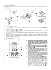
... the number of the disk contents. CHANGE I TR:t T*Z% B.T. If the counter is set to lock the disk and prevent accidental erasure of work pieces shown in the bobbin thread counter 0 to the front, and insert the disk into the drive 0. The alarm will not start even if the start switch is completed. B.T. Unlocked, writing possible Window open Locked, writing impossible (1) Turn the power...
... the number of the disk contents. CHANGE I TR:t T*Z% B.T. If the counter is set to lock the disk and prevent accidental erasure of work pieces shown in the bobbin thread counter 0 to the front, and insert the disk into the drive 0. The alarm will not start even if the start switch is completed. B.T. Unlocked, writing possible Window open Locked, writing impossible (1) Turn the power...

Instruction Manual - English
Page 13
... presser foot will reverse one stitch at a time in the reverse sewing direction to enable resewing in the event the thread breaks or the bobbin thread runs out in mid-pattern. The presser foot will go out. (3) Press the step back switch 0. Turn SPEED control 0 to adjust. (2) Refer to the table below for each stitch length. El Step back switch use C:, 0 TEST STEP BACK 0 U O I * This switch is used to move the presser foot one stitch at a time...
... presser foot will reverse one stitch at a time in the reverse sewing direction to enable resewing in the event the thread breaks or the bobbin thread runs out in mid-pattern. The presser foot will go out. (3) Press the step back switch 0. Turn SPEED control 0 to adjust. (2) Refer to the table below for each stitch length. El Step back switch use C:, 0 TEST STEP BACK 0 U O I * This switch is used to move the presser foot one stitch at a time...
Instruction Manual - English
Page 14
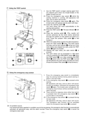
... the test mode. The work clamp advances through the pattern at low speed one stitch at a time. El Using the TEST switch GO° 0 TEST STEP BACK U / 0 * Use the TEST switch to begin sewing again from any desired point when the thread breaks or the bobbin thread runs out. (1) Press the emergency stop switch 0 while the sewing machine is running. (All operations will stop, and an...
... the test mode. The work clamp advances through the pattern at low speed one stitch at a time. El Using the TEST switch GO° 0 TEST STEP BACK U / 0 * Use the TEST switch to begin sewing again from any desired point when the thread breaks or the bobbin thread runs out. (1) Press the emergency stop switch 0 while the sewing machine is running. (All operations will stop, and an...

Instruction Manual - English
Page 16
... the starting pedal 0. (The work clamp will return to the origin, and will then advance to the sewing start position.) (7) Press the starting pedal 0 again to start sewing. (This is only required the first time a program is sewin.) (8) When sewing is completed, the thread cutter will then rise. * Rotary hook lubrication CD 0 0 (1) Pull the rotary hook cover forward to open, and then remove the bobbin case. (2) Slide the tab 0 in the direction of oil...
... the starting pedal 0. (The work clamp will return to the origin, and will then advance to the sewing start position.) (7) Press the starting pedal 0 again to start sewing. (This is only required the first time a program is sewin.) (8) When sewing is completed, the thread cutter will then rise. * Rotary hook lubrication CD 0 0 (1) Pull the rotary hook cover forward to open, and then remove the bobbin case. (2) Slide the tab 0 in the direction of oil...

Instruction Manual - English
Page 17
... line, ®, with the bottom of the needle bar bushing when using needle DP x 17. 11 Needle bar lift stroke adjustment 0 0 1 Turn the pulley to 0.01-O.08 mm. E Needle to completely lower the needle bar. STANDAR TMEN TS * Turn the machine pulley by hand when making any adjustments El Needle bar height adjustment • Turn the pulley to shuttle hook point gap adjustment 0.01-0.08 mm 0 • O 0 Turn the pulley...
... line, ®, with the bottom of the needle bar bushing when using needle DP x 17. 11 Needle bar lift stroke adjustment 0 0 1 Turn the pulley to 0.01-O.08 mm. E Needle to completely lower the needle bar. STANDAR TMEN TS * Turn the machine pulley by hand when making any adjustments El Needle bar height adjustment • Turn the pulley to shuttle hook point gap adjustment 0.01-0.08 mm 0 • O 0 Turn the pulley...

Instruction Manual - English
Page 18
... thread guide lightly in skipped stitches. El Shuttle driver needle contact adjustment )) B1111)))) 0 Turn the pulley and align the rotary hook popint with the needle center. Ei Shuttle hook thread guide adjustment Adjust so that excessive needle to driver contact will result in , and then retighten the screws. 0 0 Lightly push E Two-step work clamp adjustment (independent presser foot solenoid type) 0 00 O 1.1 0 0 0 Maximum work clamp lift is 18 mm from the needle plate top to the work clamp 0 when the machine is at this time. Adjust guide...
... thread guide lightly in skipped stitches. El Shuttle driver needle contact adjustment )) B1111)))) 0 Turn the pulley and align the rotary hook popint with the needle center. Ei Shuttle hook thread guide adjustment Adjust so that excessive needle to driver contact will result in , and then retighten the screws. 0 0 Lightly push E Two-step work clamp adjustment (independent presser foot solenoid type) 0 00 O 1.1 0 0 0 Maximum work clamp lift is 18 mm from the needle plate top to the work clamp 0 when the machine is at this time. Adjust guide...

Instruction Manual - English
Page 20
... presser foot, remove nut (small) 0, nut (large) 0, and washer 0, and then turn the presser foot (presser bar) to either 4 mm or 7 mm. 0 4 mm presser 0 foot lift 0 7 mm presser foot lift 0 (1) To change the lift of the needle hole, remove cap 0, loosen screw 0, and turn the intermittent presser foot cam 0 over. (There are two indexes, 4 and 7, on connecting lever pin 0, and install needle plate 0. If the needle is lowered too far, the work piece, and then tighten screw...
... presser foot, remove nut (small) 0, nut (large) 0, and washer 0, and then turn the presser foot (presser bar) to either 4 mm or 7 mm. 0 4 mm presser 0 foot lift 0 7 mm presser foot lift 0 (1) To change the lift of the needle hole, remove cap 0, loosen screw 0, and turn the intermittent presser foot cam 0 over. (There are two indexes, 4 and 7, on connecting lever pin 0, and install needle plate 0. If the needle is lowered too far, the work piece, and then tighten screw...
Instruction Manual - English
Page 24
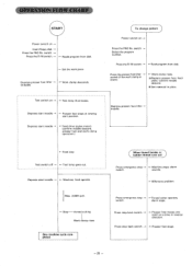
... 4-Thread cutter operates, alarm stops. OPERATION FLOW CHART, ,START] Power switch on Insert floppy disk Press the PRO No. Reads program from disk. Depress presser foot lifter treadle. 4- Press step back switch. 4- Test lamp goes out. Press the R/W switch. 4- Presser foot moves one stitch at sewing start treadle .-Feed drive (pulse motor) (confirm needle descent, presser foot and work clamp operation.) To change pattern ) Power switch on 4- Set material in reverse direction. Work clamp descends. switch. --. Work clamp rises. Remove problem Press...
... 4-Thread cutter operates, alarm stops. OPERATION FLOW CHART, ,START] Power switch on Insert floppy disk Press the PRO No. Reads program from disk. Depress presser foot lifter treadle. 4- Press step back switch. 4- Test lamp goes out. Press the R/W switch. 4- Presser foot moves one stitch at sewing start treadle .-Feed drive (pulse motor) (confirm needle descent, presser foot and work clamp operation.) To change pattern ) Power switch on 4- Set material in reverse direction. Work clamp descends. switch. --. Work clamp rises. Remove problem Press...
Programmer Instruction Manual - English
Page 6
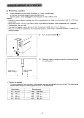
... used, draw the pattern to 2, 5, or 10 times actual size.) • Design the pattern in such a way that it will not move the needle point along the stitch pattern. The relationship between stitch length and sewing speed is shown in establishing the initial stitch position, performing a backstitch operation, or setting the sewing direction. (2) Turn the power switch Q on. /1 (3) Manually rotate the pulley to move . Tape the pattern of the needle path to the feed plate...
... used, draw the pattern to 2, 5, or 10 times actual size.) • Design the pattern in such a way that it will not move the needle point along the stitch pattern. The relationship between stitch length and sewing speed is shown in establishing the initial stitch position, performing a backstitch operation, or setting the sewing direction. (2) Turn the power switch Q on. /1 (3) Manually rotate the pulley to move . Tape the pattern of the needle path to the feed plate...

Programmer Instruction Manual - English
Page 8
... operation speed of the work clamp to program the remaining straight-line portions from point ® to point 0 will move to facilitate the programming operation. Then, press the numeral key El 3 times to indicate "111" on the STEP display, and then press the El key. (10) The work clamp will be set the proper stitch length when the actual stitch length is 3 mm, use the...
... operation speed of the work clamp to program the remaining straight-line portions from point ® to point 0 will move to facilitate the programming operation. Then, press the numeral key El 3 times to indicate "111" on the STEP display, and then press the El key. (10) The work clamp will be set the proper stitch length when the actual stitch length is 3 mm, use the...


