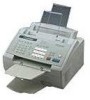

Service Manual
Page 4
... Road, Wuhe Street Bantian Industry Zone, Buji Shenzhen, P. SAFETY INFORMATION Laser Safety (110-120V Model only) This printer is certified as a Class 1 laser product under the US Department of Health and Human Services (DHHS) Radiation Performance Standard according to laser products manufactured from the machine during any phase of user operation. The label for products marketed in the United States.
... Road, Wuhe Street Bantian Industry Zone, Buji Shenzhen, P. SAFETY INFORMATION Laser Safety (110-120V Model only) This printer is certified as a Class 1 laser product under the US Department of Health and Human Services (DHHS) Radiation Performance Standard according to laser products manufactured from the machine during any phase of user operation. The label for products marketed in the United States.
Service Manual
Page 9
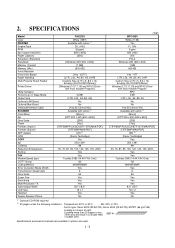
SPECIFICATIONS (1/2) Model Color PRINTER Engine/Type PPM dpi (output resolution) Paper Capacity Emulation (Standard) Standards Memory (Typical) Memory (Min.) Fonts Resident Fonts Disk Based Paper Handling Multi-Purpose Sheet Feeder Printer Driver Utility Software Period to go in brackets are available if options are used. Loading as shown at right. (Loading more than 20 pages in any other way will result in a double feed or paper jam.) Specifications enclosed in Sleep Mode Output Size Optional LAN Board Optional Mac Board Interface/Interface Cable SCANNER Color/Mono dpi Gray Scale Twain ...
SPECIFICATIONS (1/2) Model Color PRINTER Engine/Type PPM dpi (output resolution) Paper Capacity Emulation (Standard) Standards Memory (Typical) Memory (Min.) Fonts Resident Fonts Disk Based Paper Handling Multi-Purpose Sheet Feeder Printer Driver Utility Software Period to go in brackets are available if options are used. Loading as shown at right. (Loading more than 20 pages in any other way will result in a double feed or paper jam.) Specifications enclosed in Sleep Mode Output Size Optional LAN Board Optional Mac Board Interface/Interface Cable SCANNER Color/Mono dpi Gray Scale Twain ...
Service Manual
Page 10
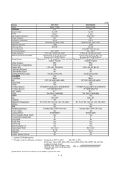
... any other way will result in a double feed or paper jam.) Specifications enclosed in Sleep Mode Output Size Optional LAN Board Optional Mac Board Interface/Interface Cable SCANNER Color/Mono dpi Gray Scale Twain Formats (Import) Formats (Export) ADF (pages) OCR Yes Yes YL (VA) YL (VA) 6 ppm 6 ppm 600 x 600 600 x 600 200 200 PCL4 PCL4 Windows GDI (600 x 600) Windows GDI (600 x 600) 1 MB 1 MB 600 KB...
... any other way will result in a double feed or paper jam.) Specifications enclosed in Sleep Mode Output Size Optional LAN Board Optional Mac Board Interface/Interface Cable SCANNER Color/Mono dpi Gray Scale Twain Formats (Import) Formats (Export) ADF (pages) OCR Yes Yes YL (VA) YL (VA) 6 ppm 6 ppm 600 x 600 600 x 600 200 200 PCL4 PCL4 Windows GDI (600 x 600) Windows GDI (600 x 600) 1 MB 1 MB 600 KB...
Service Manual
Page 11
...: 20°C to 70% - Specifications enclosed in brackets are available if options are used . (1/2) Model FAX-8050P FAX-8250P Color PRINTER Engine/Type PPM dpi (output resolution) Paper Capacity Emulation (Standard) Standards Memory (Typical) Memory (Min.) Fonts Resident Fonts Disk Based Paper Handling Multi-Purpose Sheet Feeder Printer Driver Utility Software Period to go in a double feed or paper jam.) *2 Available, if HL-720 printer driver is used . White (1397) Available with option *1 [YL (VA)] [6 ppm] [600 x 600] [200] - [Windows GDI (600 x 600)] [1 MB...
...: 20°C to 70% - Specifications enclosed in brackets are available if options are used . (1/2) Model FAX-8050P FAX-8250P Color PRINTER Engine/Type PPM dpi (output resolution) Paper Capacity Emulation (Standard) Standards Memory (Typical) Memory (Min.) Fonts Resident Fonts Disk Based Paper Handling Multi-Purpose Sheet Feeder Printer Driver Utility Software Period to go in a double feed or paper jam.) *2 Available, if HL-720 printer driver is used . White (1397) Available with option *1 [YL (VA)] [6 ppm] [600 x 600] [200] - [Windows GDI (600 x 600)] [1 MB...
Service Manual
Page 12
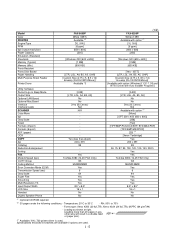
... result in a double feed or paper jam.) Specifications enclosed in Sleep Mode Output Size Optional LAN Board Optional Mac Board Interface Interface Cable SCANNER Color/Mono dpi Gray Scale Twain Formats (Import) Formats (Export) ADF (pages) OCR COPY dpi Collating Reduction/Enlargement Sorting FAX Modem/Speed (bps) CCITT Group Coding Method Error Correction Mode (ECM) Transmission Speed (sec) Gray Scale Super Fine Smoothing Multi-Resolution TX Input/Output Width LCD Size Handset Duplex Speaker Phone...
... result in a double feed or paper jam.) Specifications enclosed in Sleep Mode Output Size Optional LAN Board Optional Mac Board Interface Interface Cable SCANNER Color/Mono dpi Gray Scale Twain Formats (Import) Formats (Export) ADF (pages) OCR COPY dpi Collating Reduction/Enlargement Sorting FAX Modem/Speed (bps) CCITT Group Coding Method Error Correction Mode (ECM) Transmission Speed (sec) Gray Scale Super Fine Smoothing Multi-Resolution TX Input/Output Width LCD Size Handset Duplex Speaker Phone...

Service Manual
Page 19
.... (2) Make sure that your computer is replaced, install the update program onto the flash ROM of your computer and secure it with the two screws. (5) Power on your computer. (6) Plug the equipment's power cord into a wall socket. INSTALLING THE UPDATE DATA TO THE FACSIMILE EQUIPMENT If the program version is updated or the main PCB is powered off. (3) Connect the interface cable to the parallel interface port...
.... (2) Make sure that your computer is replaced, install the update program onto the flash ROM of your computer and secure it with the two screws. (5) Power on your computer. (6) Plug the equipment's power cord into a wall socket. INSTALLING THE UPDATE DATA TO THE FACSIMILE EQUIPMENT If the program version is updated or the main PCB is powered off. (3) Connect the interface cable to the parallel interface port...

Service Manual
Page 32
... Document front sensor Document rear sensor Top cover sensor Sheet feeder cover sensor Registration sensor Paper ejection sensor Toner sensor Toner thermister Heater thermister Hook switch* Type Photosensor Photosensor Photosensor Photosensor Photosensor Photosensor Photosensor Thermister Thermister Mechanical switch Located on Control panel PCB ASSY (Document sensor PCB) Control panel PCB ASSY (Document sensor PCB) Main PCB Main PCB Main PCB High-voltage power supply PCB Toner sensor PCB Toner sensor PCB Heat-fixing unit Hook switch PCB* *Not provided on the FAX-8250P/MFC-9050...
... Document front sensor Document rear sensor Top cover sensor Sheet feeder cover sensor Registration sensor Paper ejection sensor Toner sensor Toner thermister Heater thermister Hook switch* Type Photosensor Photosensor Photosensor Photosensor Photosensor Photosensor Photosensor Thermister Thermister Mechanical switch Located on Control panel PCB ASSY (Document sensor PCB) Control panel PCB ASSY (Document sensor PCB) Main PCB Main PCB Main PCB High-voltage power supply PCB Toner sensor PCB Toner sensor PCB Heat-fixing unit Hook switch PCB* *Not provided on the FAX-8250P/MFC-9050...
Service Manual
Page 45
... before replacing parts or units. When having access to the power supply, be sure to remove that the connectors and other reflective objects in the path of the laser printing unit, be put back in aluminum foil). Failure to do so may be sure to unplug the power cord from the power outlet before working on the next page. (11) When connecting or disconnecting cable connectors...
... before replacing parts or units. When having access to the power supply, be sure to remove that the connectors and other reflective objects in the path of the laser printing unit, be put back in aluminum foil). Failure to do so may be sure to unplug the power cord from the power outlet before working on the next page. (11) When connecting or disconnecting cable connectors...
Service Manual
Page 76
... left-hand battery support. IV - 32 n Reassembling Notes • Route the hook switch harness (red), solenoid harness (blue), and main motor harness through three latches "w," "y" and "z." • At the rear side of the main cover. (2) Remove the screw from the main PCB. (3) Slightly lift up the main PCB and disconnect it from the low-voltage power supply PCB. (4) Disconnect...
... left-hand battery support. IV - 32 n Reassembling Notes • Route the hook switch harness (red), solenoid harness (blue), and main motor harness through three latches "w," "y" and "z." • At the rear side of the main cover. (2) Remove the screw from the main PCB. (3) Slightly lift up the main PCB and disconnect it from the low-voltage power supply PCB. (4) Disconnect...

Service Manual
Page 95
... Subsection (Page) 3.1 (V-4) Printout of Scanning Compensation Data 3.2 (V-5) ADF* Performance Test Test Pattern 1 Firmware Switch Setting Printout of Firmware Switch Data Operational Check of LCD Operational Check of Control Panel PCB (Check of Keys and Buttons) 3.3 (V-7) 3.4 (V-8) 3.5 (V-9) 3.5 (V-50) 3.6 (V-51) 3.7 (V-51) Sensor Operational Check CIS Scanner Area Setting EEPROM Customizing Equipment Error Code Indication Output of Transmission Log to the Telephone Line EEPROM Parameter Initialization (except the telephone number storage area) Exit from the Maintenance Mode 3.8 (V-54...
... Subsection (Page) 3.1 (V-4) Printout of Scanning Compensation Data 3.2 (V-5) ADF* Performance Test Test Pattern 1 Firmware Switch Setting Printout of Firmware Switch Data Operational Check of LCD Operational Check of Control Panel PCB (Check of Keys and Buttons) 3.3 (V-7) 3.4 (V-8) 3.5 (V-9) 3.5 (V-50) 3.6 (V-51) 3.7 (V-51) Sensor Operational Check CIS Scanner Area Setting EEPROM Customizing Equipment Error Code Indication Output of Transmission Log to the Telephone Line EEPROM Parameter Initialization (except the telephone number storage area) Exit from the Maintenance Mode 3.8 (V-54...

Service Manual
Page 102
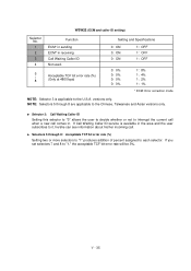
The firmware switch data list indicates "Not used." The firmware switches have been set at the factory in some versions. Do not disturb them unless necessary. Firmware Switches (WSW01 through WSW36) which may not be activated with the procedures using the control panel keys and buttons. 3.5 Firmware Switch Setting and Printout [ A ] Firmware switch setting n Function The facsimile equipment incorporates the following firmware switch functions (WSW01 through WSW36) WSW No. WSW01 WSW02 WSW03 WSW04 WSW05...
The firmware switch data list indicates "Not used." The firmware switches have been set at the factory in some versions. Do not disturb them unless necessary. Firmware Switches (WSW01 through WSW36) which may not be activated with the procedures using the control panel keys and buttons. 3.5 Firmware Switch Setting and Printout [ A ] Firmware switch setting n Function The facsimile equipment incorporates the following firmware switch functions (WSW01 through WSW36) WSW No. WSW01 WSW02 WSW03 WSW04 WSW05...

Service Manual
Page 115
...lines with higher bit error rate, however, set to "1," the equipment will use non-standard commands (the machine's native-mode commands, e.g., NSF, NSC, and NSS) for time-out control If the equipment receives no response (no response from the called station in which do not support ECM. l Selector 5: T5 timer This selector sets the time... 8: Elapsed time for communications. l Selector 2: Use of retries These selectors set to "1" so that if any data error occurs on the transmission line, the equipment retransmits only those models which the equipment divides a message into 64-...
...lines with higher bit error rate, however, set to "1," the equipment will use non-standard commands (the machine's native-mode commands, e.g., NSF, NSC, and NSS) for time-out control If the equipment receives no response (no response from the called station in which do not support ECM. l Selector 5: T5 timer This selector sets the time... 8: Elapsed time for communications. l Selector 2: Use of retries These selectors set to "1" so that if any data error occurs on the transmission line, the equipment retransmits only those models which the equipment divides a message into 64-...

Service Manual
Page 125
... automatically steps down the transmission speed to set speed automatically reduced to those models that support 14,400 bps. V - 32 WSW19 (Transmission speed setting) Selector No. With the first transmission ...used . 8 V. 17 mode Setting and Specifications No. 1 2 3 No. 4 5 6 000 : 001 : 010 : 011 : 100 : 101 : 110 : 111 : 2,400 bps 4,800 bps 7,200 bps 9,600 bps 12,000 bps * 14,400 bps * 0: Permitted 1: Prohibited * In those models with a maximum of 9600 bps capability, selection of transmission speed for shorter transmission time. Generally, to save the transmission time, set...
... automatically steps down the transmission speed to set speed automatically reduced to those models that support 14,400 bps. V - 32 WSW19 (Transmission speed setting) Selector No. With the first transmission ...used . 8 V. 17 mode Setting and Specifications No. 1 2 3 No. 4 5 6 000 : 001 : 010 : 011 : 100 : 101 : 110 : 111 : 2,400 bps 4,800 bps 7,200 bps 9,600 bps 12,000 bps * 14,400 bps * 0: Permitted 1: Prohibited * In those models with a maximum of 9600 bps capability, selection of transmission speed for shorter transmission time. Generally, to save the transmission time, set...
Service Manual
Page 128
...Setting this selector to "0" allows the user to decide whether or not to interrupt the current call when a new call . versions only. If Call Waiting Caller ID service is applicable to the U.S.A. NOTE: Selectors 5 through 8: Acceptable TCF bit error rate (%) Setting... Call Waiting Caller ID Not used. 5 | 8 Acceptable TCF bit error rate (%) (Only at 4800 bps) Setting and Specifications 0: ON 0: ON 0: ON 1: OFF 1: OFF 1: OFF 0: 0% 0: 0% 0: 0% 0: 0% 1: 8% 1: 4% 1: 2% 1: 1% * ECM: Error correction mode NOTE: Selector 3 is available in the area and the user subscribes to it, he/she...
...Setting this selector to "0" allows the user to decide whether or not to interrupt the current call when a new call . versions only. If Call Waiting Caller ID service is applicable to the U.S.A. NOTE: Selectors 5 through 8: Acceptable TCF bit error rate (%) Setting... Call Waiting Caller ID Not used. 5 | 8 Acceptable TCF bit error rate (%) (Only at 4800 bps) Setting and Specifications 0: ON 0: ON 0: ON 1: OFF 1: OFF 1: OFF 0: 0% 0: 0% 0: 0% 0: 0% 1: 8% 1: 4% 1: 2% 1: 1% * ECM: Error correction mode NOTE: Selector 3 is available in the area and the user subscribes to it, he/she...

Service Manual
Page 133
... sampling rate by the user function 8-8). if it is set to High Toner save mode Setting and Specifications 0: TEL key 1: TEL/POLLING key 0: Yes 1: No 0: No 1: Yes 0: Yes 1: No 0: Normal 1: High 0: Short 1: Long 0: Yes 1: No NOTE: Selector 1 is off or on the hook, respectively. l Selector 6: Recording quality level This selector determines the recording quality level (this selector to...
... sampling rate by the user function 8-8). if it is set to High Toner save mode Setting and Specifications 0: TEL key 1: TEL/POLLING key 0: Yes 1: No 0: No 1: Yes 0: Yes 1: No 0: Normal 1: High 0: Short 1: Long 0: Yes 1: No NOTE: Selector 1 is off or on the hook, respectively. l Selector 6: Recording quality level This selector determines the recording quality level (this selector to...
Service Manual
Page 147
... registration sensor, open the sheet feeder cover or the top cover, jam paper at the paper outlet, remove the toner cartridge, and lift up the handset), and then check that the indication on -hook state (HK). the toner sensor detects toner (TN). V - 54 the document rear sensor detects no paper (RE), - the paper ejection sensor detects no hook switch sensor.) In the FAX-8250P/MFC-9050, the LCD shows the "FRRETCCVRGHATN" when - the sheet feeder cover is...
... registration sensor, open the sheet feeder cover or the top cover, jam paper at the paper outlet, remove the toner cartridge, and lift up the handset), and then check that the indication on -hook state (HK). the toner sensor detects toner (TN). V - 54 the document rear sensor detects no paper (RE), - the paper ejection sensor detects no hook switch sensor.) In the FAX-8250P/MFC-9050, the LCD shows the "FRRETCCVRGHATN" when - the sheet feeder cover is...

Service Manual
Page 154
... the white level data is faulty. (This message may appear only in the maintenance mode.) TONER LOW The toner sensor has detected that the toner temperature exceeded the specified level. "XX" indicates an error code. Refer to [ 2 ] on pages VI-4 and VI-5. The service life of the drum unit will expire soon. COOLING DOWN PLEASE WAIT (Appear alternately.) MACHINE ERROR XX PRESS STOP KEY (Appear alternately.) CHANGE DRUM SOON PC...
... the white level data is faulty. (This message may appear only in the maintenance mode.) TONER LOW The toner sensor has detected that the toner temperature exceeded the specified level. "XX" indicates an error code. Refer to [ 2 ] on pages VI-4 and VI-5. The service life of the drum unit will expire soon. COOLING DOWN PLEASE WAIT (Appear alternately.) MACHINE ERROR XX PRESS STOP KEY (Appear alternately.) CHANGE DRUM SOON PC...

Service Manual
Page 168
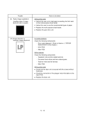
... drum unit. and † in the illustration given on page VI-21) l Check the connection of the main-high-voltage flat cable. l Replace the main PCB. Main PCB - CIS harness - [ 5 ] Print-image related If the received or sent image has any problem, first make a copy with the facsimile equipment. If the copied image is abnormal, proceed to the following components: - VI - 16 CIS unit At the printer side l Clean...
... drum unit. and † in the illustration given on page VI-21) l Check the connection of the main-high-voltage flat cable. l Replace the main PCB. Main PCB - CIS harness - [ 5 ] Print-image related If the received or sent image has any problem, first make a copy with the facsimile equipment. If the copied image is abnormal, proceed to the following components: - VI - 16 CIS unit At the printer side l Clean...

Service Manual
Page 169
... cover, and high-voltage power supply PCB. (Contacts ... Main PCB At the printer side l Slide the wire cleaner tab to the next step. If the problem persists, proceed to clean the corona wire inside the drum unit. l Remove the toner cartridge and start printing. l Replace the drum unit. CIS unit - VI - 17 Main PCB At the printer side l Replace the toner cartridge with a new one and print 4 to 5 pages. If printing takes place, clean the toner sensor or replace the toner sensor...
... cover, and high-voltage power supply PCB. (Contacts ... Main PCB At the printer side l Slide the wire cleaner tab to the next step. If the problem persists, proceed to clean the corona wire inside the drum unit. l Remove the toner cartridge and start printing. l Replace the drum unit. CIS unit - VI - 17 Main PCB At the printer side l Replace the toner cartridge with a new one and print 4 to 5 pages. If printing takes place, clean the toner sensor or replace the toner sensor...
Service Manual
Page 171
... connection of the polygon motor flat cable on the multi-purpose sheet feeder. Error code displayed. (Refer to use the recommended types of paper. Main PCB At the printer side l Check that the laser unit is secured with the screws without looseness. VI - 19 Main PCB At the scanner Check the following components: - Scanner motor and its related sections - l Replace the laser unit. Document feed rollers and their related gears - Trouble (9) Faulty image...
... connection of the polygon motor flat cable on the multi-purpose sheet feeder. Error code displayed. (Refer to use the recommended types of paper. Main PCB At the printer side l Check that the laser unit is secured with the screws without looseness. VI - 19 Main PCB At the scanner Check the following components: - Scanner motor and its related sections - l Replace the laser unit. Document feed rollers and their related gears - Trouble (9) Faulty image...


