
User Manual
Page 2
... PH2.600 PH2.800 PH2.1000 PH2.1300 PH2.1500 Two Channel MOSFET Car Audio Amplifiers PH4.400M PH4.500M PH4.600M PH4.700M Four Channel MOSFET Car Audio Amplifiers PH1500M MonoBlock PH1502MW MOpSgeTrsCar Am Audio PH2500M Congratulations on your choice for car audio entertainment! It has been designed, engineered and manufactured to bring you the highest...
... PH2.600 PH2.800 PH2.1000 PH2.1300 PH2.1500 Two Channel MOSFET Car Audio Amplifiers PH4.400M PH4.500M PH4.600M PH4.700M Four Channel MOSFET Car Audio Amplifiers PH1500M MonoBlock PH1502MW MOpSgeTrsCar Am Audio PH2500M Congratulations on your choice for car audio entertainment! It has been designed, engineered and manufactured to bring you the highest...
User Manual
Page 3
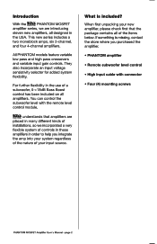
... amp into your system regardless of the nature of your new amplifier, please check first that amplifiers are placed in many different kinds of installations, so we are introducing eleven new amplifiers, all designed in the USA. When first unpacking your input ... • Four (4) mounting screws PHANTOM MOSFET Amplifier User's Manual - Introduction With the MS PHANTOM MOSFET amplifier series, we incorporated a very flexible system of controls in these amplifiers in order to help you purchased the amplifier. • PHANTOM amplifier • Remote subwoofer level control •...
... amp into your system regardless of the nature of your new amplifier, please check first that amplifiers are placed in many different kinds of installations, so we are introducing eleven new amplifiers, all designed in the USA. When first unpacking your input ... • Four (4) mounting screws PHANTOM MOSFET Amplifier User's Manual - Introduction With the MS PHANTOM MOSFET amplifier series, we incorporated a very flexible system of controls in these amplifiers in order to help you purchased the amplifier. • PHANTOM amplifier • Remote subwoofer level control •...

User Manual
Page 4
... This means that you lack adequate current, your power output by approximately 50%. The current draw will be distorted. PHANTOM MOSFET Amplifier User's Manual - If you can install four 8 Ohm speakers per speaker. Increasing the number of an additional 10W per channel..., when using parallel wiring. Features Your new PHANTOM amplifier features the following: • Class A-B operation • Bridgeable outputs (except PH1500M, PH1502MW, PH2500M ) • Tri-Mode capable (except PH1500M and PH2500M) • MOSFET PWM (Pulse ...
... This means that you lack adequate current, your power output by approximately 50%. The current draw will be distorted. PHANTOM MOSFET Amplifier User's Manual - If you can install four 8 Ohm speakers per speaker. Increasing the number of an additional 10W per channel..., when using parallel wiring. Features Your new PHANTOM amplifier features the following: • Class A-B operation • Bridgeable outputs (except PH1500M, PH1502MW, PH2500M ) • Tri-Mode capable (except PH1500M and PH2500M) • MOSFET PWM (Pulse ...

User Manual
Page 5
... location. 3. If you wish to prevent damage, especially in electric shock. Mounting the amplifier 1. Find a suitable location in the vehicle in which may result in damage to your audio system or your car's layout very carefully. Mark the location for the mounting hole screws... power connections in position, and attach the amplifier to mark the mounting surface. Never operate the amplifier when it is carpeted, measure the hole centers and mark with all audio system components securely to install it only with the amplifier. There are no user-serviceable parts within...
... location. 3. If you wish to prevent damage, especially in electric shock. Mounting the amplifier 1. Find a suitable location in the vehicle in which may result in damage to your audio system or your car's layout very carefully. Mark the location for the mounting hole screws... power connections in position, and attach the amplifier to mark the mounting surface. Never operate the amplifier when it is carpeted, measure the hole centers and mark with all audio system components securely to install it only with the amplifier. There are no user-serviceable parts within...

User Manual
Page 6
... ground points. 6. Do not adjust this manual and identify the diagrams to the amplifier, and excessive audio distortion. page 5 Then run 8 gauge (or heavier) cable from the amplifier to each amplifier. Insert fuse(s) into the battery fuse holder(s). 8. Power up the amplifier. 9. Further fine tuning of the car battery, and run separate cables from this...
... ground points. 6. Do not adjust this manual and identify the diagrams to the amplifier, and excessive audio distortion. page 5 Then run 8 gauge (or heavier) cable from the amplifier to each amplifier. Insert fuse(s) into the battery fuse holder(s). 8. Power up the amplifier. 9. Further fine tuning of the car battery, and run separate cables from this...

User Manual
Page 7
....61 R- " =NM gl"i I . .. . Ca, 'WSW 0 3024, © ID TWO CHANNEL MOSPET POWER AMPLIFIER 0 O ) DI ''-o c I C )r )c ) r ) 0 I ' - 1--It To Audio Outputs of head unit or signal processor O 000000 4-Channel Amplifiers PH4.400, PH4.500, PH4.600 and PH4.700 I ,i DE --i_r- Ep maM r INI CU DI te..,, LOW... CH1/2 3O S C hM III -L_E Lun o um AVOWER ID ID uunferr O Om full Ion IWIER oX M R CHANNEL MOEIF, POWER AMPLIFIER C ID (0 ) ID O To FRONT Audio Outputs of head unit or signal processor Low Level Input Wiring Low-level (RCA) input wiring is preferred for best...
....61 R- " =NM gl"i I . .. . Ca, 'WSW 0 3024, © ID TWO CHANNEL MOSPET POWER AMPLIFIER 0 O ) DI ''-o c I C )r )c ) r ) 0 I ' - 1--It To Audio Outputs of head unit or signal processor O 000000 4-Channel Amplifiers PH4.400, PH4.500, PH4.600 and PH4.700 I ,i DE --i_r- Ep maM r INI CU DI te..,, LOW... CH1/2 3O S C hM III -L_E Lun o um AVOWER ID ID uunferr O Om full Ion IWIER oX M R CHANNEL MOEIF, POWER AMPLIFIER C ID (0 ) ID O To FRONT Audio Outputs of head unit or signal processor Low Level Input Wiring Low-level (RCA) input wiring is preferred for best...

User Manual
Page 8
... AMPLIFIER c ) ( ) c ) ( ) c ) ICI a To Audio Outputs of head unit or signal processor O PHANTOM MOSFET Amplifier User's Manual - INS MOM MIK MIAS, ...,...... .0 -70,0071 MM., oneemx e III ID ID „,\ (- OOO I.-, I Ma: ''' ' -fl OM 0 .1.00 L1 -.4 0 -Li- NOTE:Do not connectBOTH the high levelandlowlevelinputs from your receiver to your amplifier at the same time! MonoBlock Amplifier PHI500M, PH1502MW...
... AMPLIFIER c ) ( ) c ) ( ) c ) ICI a To Audio Outputs of head unit or signal processor O PHANTOM MOSFET Amplifier User's Manual - INS MOM MIK MIAS, ...,...... .0 -70,0071 MM., oneemx e III ID ID „,\ (- OOO I.-, I Ma: ''' ' -fl OM 0 .1.00 L1 -.4 0 -Li- NOTE:Do not connectBOTH the high levelandlowlevelinputs from your receiver to your amplifier at the same time! MonoBlock Amplifier PHI500M, PH1502MW...

User Manual
Page 9
MUM WRIF MEM ......... MINIM CORRAY a EIH O. NEC I . lull 0 . HEMP ...... 30by TWO CHANNEL MOSFET POWER AMPLIFIER /C /c /C /C /C ) El 0 14/W -1 (9 iVI 0 R+ R- DI clam 6'e±e'emm-, ma-, c"74„,...7.„1O,...1, O1 O I RENEW Mq ,,,,, , . Be sure to observe polarity to avoid audio phase problems. NOTE:Do not connectBOTH the high levelandlowlevelinputs from the receiver to 0 A.rr, IC...
MUM WRIF MEM ......... MINIM CORRAY a EIH O. NEC I . lull 0 . HEMP ...... 30by TWO CHANNEL MOSFET POWER AMPLIFIER /C /c /C /C /C ) El 0 14/W -1 (9 iVI 0 R+ R- DI clam 6'e±e'emm-, ma-, c"74„,...7.„1O,...1, O1 O I RENEW Mq ,,,,, , . Be sure to observe polarity to avoid audio phase problems. NOTE:Do not connectBOTH the high levelandlowlevelinputs from the receiver to 0 A.rr, IC...

User Manual
Page 10
L- Be sure to observe polarity to avoid audio phase problems. NOTE:Do not connectBOTH the high levelandlowlevelinputs from the receiver to your head unit lacks RCA outputs. ... MOSFET Amplifier User's Manual - L+ To Speaker Terminals of the amplifier. ar .0. - High Level Input Wiring The high level input(s) should only be used when your amplifier at w MEE ORM ° 0 N0TECT0X -L_E ..,...., ElEll 0 Ell ME ......' 0 DElIl L- r 1 l r lr 3obb ) \w., 0 l r MOSFET MONOBLOOK POWER AMPLIFIER 1r l r 1r 1 , 0 R+ R- MonoBlock Amplifier PHI500M, PH1502MW, PH2500M...
L- Be sure to observe polarity to avoid audio phase problems. NOTE:Do not connectBOTH the high levelandlowlevelinputs from the receiver to your head unit lacks RCA outputs. ... MOSFET Amplifier User's Manual - L+ To Speaker Terminals of the amplifier. ar .0. - High Level Input Wiring The high level input(s) should only be used when your amplifier at w MEE ORM ° 0 N0TECT0X -L_E ..,...., ElEll 0 Ell ME ......' 0 DElIl L- r 1 l r lr 3obb ) \w., 0 l r MOSFET MONOBLOOK POWER AMPLIFIER 1r l r 1r 1 , 0 R+ R- MonoBlock Amplifier PHI500M, PH1502MW, PH2500M...
User Manual
Page 11
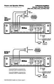
Chassis = ground point to REMOTE TURN-ON terminal of the subwoofer to the L (+) amplifier terminal. uA r E0 l *-1.-C) 0-R-0 FUSS +1 vi --RIBION ID ED _Ft Li SPEAKER CONNECNONS l I II I Connect the Positive (+) terminal of head unit O l=l ...[ 0© c I t )( )( 7( )( 7( IC 1 El Chassis = ground point FUSE to REMOTE TURN-ON terminal of the subwoofer to the R (-) amplifier terminal. Power and Speaker Wiring 2 Channel and Bridged Modes 2 -Channel Amplifiers PH2.500, PH2.600, PH2.800, PH2.1000, PH2.1300, and PH2.1500 LEFT Speaker Two Channel Mode RIGHT Speaker...
Chassis = ground point to REMOTE TURN-ON terminal of the subwoofer to the L (+) amplifier terminal. uA r E0 l *-1.-C) 0-R-0 FUSS +1 vi --RIBION ID ED _Ft Li SPEAKER CONNECNONS l I II I Connect the Positive (+) terminal of head unit O l=l ...[ 0© c I t )( )( 7( )( 7( IC 1 El Chassis = ground point FUSE to REMOTE TURN-ON terminal of the subwoofer to the R (-) amplifier terminal. Power and Speaker Wiring 2 Channel and Bridged Modes 2 -Channel Amplifiers PH2.500, PH2.600, PH2.800, PH2.1000, PH2.1300, and PH2.1500 LEFT Speaker Two Channel Mode RIGHT Speaker...

User Manual
Page 12
... Low pass filter inductor Subwoofer SPEAKER IMPEDANCE 8 OHMS L Chassis ground point L.-- To set up the amplifier to run in MONO. Component values for the crossover frequency you to connect this amplifier to a pair of main speakers plus a subwoofer on one pair of head unit O FUSE Battery ...COME17101IS I - Insert high pass filter capacitors and a low pass filter inductor into the wiring as shown below. Power and Speaker Wiring 2-Channel Amplifiers Td-Mode PH2.500, PH2.600, PH2.800, PH2.1000, PH2.1300, and PH2.1500 Tri-mode operation allows you wish to achieve.
... Low pass filter inductor Subwoofer SPEAKER IMPEDANCE 8 OHMS L Chassis ground point L.-- To set up the amplifier to run in MONO. Component values for the crossover frequency you to connect this amplifier to a pair of main speakers plus a subwoofer on one pair of head unit O FUSE Battery ...COME17101IS I - Insert high pass filter capacitors and a low pass filter inductor into the wiring as shown below. Power and Speaker Wiring 2-Channel Amplifiers Td-Mode PH2.500, PH2.600, PH2.800, PH2.1000, PH2.1300, and PH2.1500 Tri-mode operation allows you wish to achieve.

User Manual
Page 13
... terminal of head unit O FUSE Battery Connect the Negative (-) terminal of the RIGHT subwoofer to the CH2 (-) amplifier terminal. Connect the Positive (-F) terminal of the RIGHT subwoofer to the CHI (+) amplifier terminal. 0 8888 ei1818ei n 0 yi ogi i LEI_ 0 Ell 0 0 Ell Ell 0 CH1-8 C, ...WEI Bridged Mode LEFT Subwoofer SPEAKER IMPEDANCE 4-8 OHMS Connect the Negative (-) terminal of head unit O FUSE Battery PHANTOM MOSFET Amplifier User's Manual - CH4 D SPEAKER CONNECTIONS I ll 1. ' 'I 30hS ,,,,. Chassis ground point to REMOTE TURN-ON terminal of the LEFT subwoofer to the...
... terminal of head unit O FUSE Battery Connect the Negative (-) terminal of the RIGHT subwoofer to the CH2 (-) amplifier terminal. Connect the Positive (-F) terminal of the RIGHT subwoofer to the CHI (+) amplifier terminal. 0 8888 ei1818ei n 0 yi ogi i LEI_ 0 Ell 0 0 Ell Ell 0 CH1-8 C, ...WEI Bridged Mode LEFT Subwoofer SPEAKER IMPEDANCE 4-8 OHMS Connect the Negative (-) terminal of head unit O FUSE Battery PHANTOM MOSFET Amplifier User's Manual - CH4 D SPEAKER CONNECTIONS I ll 1. ' 'I 30hS ,,,,. Chassis ground point to REMOTE TURN-ON terminal of the LEFT subwoofer to the...

User Manual
Page 14
... speakers will operate in STEREO while the subwoofer simultaneously operates in the FULL position. Be sure to check the table at the bottom of this amplifier to a pair of main speakers plus a subwoofer on one pair of head unit FUSE I=I E Erl Ell cm SS2 a SI CIYX PIS .3-0 0-.4 ...high pass filter capacitors and a low pass filter inductor into the wiring as shown below. m- 8888 ° ° IY IIWIUI I Battery PHANTOM MOSFET Amplifier User's Manual - H FIRa.1.1 rosy, IRMO ILJ ,r.%e E_l DI - 111 0 SPEAKER IMPEDANCE 8 OHMS High pass filter crossover CH2 Speaker High pass ...
... speakers will operate in STEREO while the subwoofer simultaneously operates in the FULL position. Be sure to check the table at the bottom of this amplifier to a pair of main speakers plus a subwoofer on one pair of head unit FUSE I=I E Erl Ell cm SS2 a SI CIYX PIS .3-0 0-.4 ...high pass filter capacitors and a low pass filter inductor into the wiring as shown below. m- 8888 ° ° IY IIWIUI I Battery PHANTOM MOSFET Amplifier User's Manual - H FIRa.1.1 rosy, IRMO ILJ ,r.%e E_l DI - 111 0 SPEAKER IMPEDANCE 8 OHMS High pass filter crossover CH2 Speaker High pass ...

User Manual
Page 15
Power and Speaker Wiring MonoBlock Mode MonoBlock Amplifiers PH1500M, PH1502MW, PH2500M MonoBlock Mode Speaker SPEAKER IMPEDANCE 2-8 OHMS ( ) Ell Ell Ell Ell Ell 8 , SPEAKER COMMON 0 0 CEE 30bb 0 0 FUSES H\ThL _\,Th,_ .\, _1, _ +. - POWER CININECI1ONS E E0 l 0 0 ER © c 1 c ) c l c 7 c l c 7 r l c ) c c4ki-.0,. 0 Chassis ground point to REMOTE TURN-ON terminal of head unit O FUSE Battery PHANTOM MOSFET Amplifier User's Manual - page 14 t.i.„G..
Power and Speaker Wiring MonoBlock Mode MonoBlock Amplifiers PH1500M, PH1502MW, PH2500M MonoBlock Mode Speaker SPEAKER IMPEDANCE 2-8 OHMS ( ) Ell Ell Ell Ell Ell 8 , SPEAKER COMMON 0 0 CEE 30bb 0 0 FUSES H\ThL _\,Th,_ .\, _1, _ +. - POWER CININECI1ONS E E0 l 0 0 ER © c 1 c ) c l c 7 c l c 7 r l c ) c c4ki-.0,. 0 Chassis ground point to REMOTE TURN-ON terminal of head unit O FUSE Battery PHANTOM MOSFET Amplifier User's Manual - page 14 t.i.„G..

User Manual
Page 16
...route them away from speakers. Check that all speaker wiring. Check for improperly grounded RCA interconnects. Remove speaker leads, and reset the amplifier. It is best to prevent overdriving. Thi best subjective signal-to match the signal level of the head unit. Check that the .... No output. If the Protection LED stil comes on the previous pages. Check that the RCA audio cables are not shorted to set to -noise ratio is achievedin this point, go on the (+) terminal. PHANTOM MOSFET Amplifier User's Manual - Troubleshooting If you have a good ground connection.
...route them away from speakers. Check that all speaker wiring. Check for improperly grounded RCA interconnects. Remove speaker leads, and reset the amplifier. It is best to prevent overdriving. Thi best subjective signal-to match the signal level of the head unit. Check that the .... No output. If the Protection LED stil comes on the previous pages. Check that the RCA audio cables are not shorted to set to -noise ratio is achievedin this point, go on the (+) terminal. PHANTOM MOSFET Amplifier User's Manual - Troubleshooting If you have a good ground connection.

User Manual
Page 17
...impedance 2 Ohm Stereo 4 Ohm Mono Bridged THD 0.01% Frequency repp 9Hz-50kHz Signal-to change without notice. Specifications 3053 AUDIO SYSTEMS MODEL 2-Channel MOSFET Amplifiers PH2.500 PH2.600 PH2.800 MAX POWER into 2 Ohms 500W x 2 600W x 2 RMS POWER into 4 Ohms ...x 2 40A x 2 Dimensions: 9-v2• x 2-1/4" x (241mm x 57.2mm x...) 13-7/16" (343mm) 15-1/2" (394mm) 17" (432mm) 22" (558mm) MonoBlock MOSFET Amplifiers PH1502MW PH1500M PH2500M 1500W x 1 2500W x 1 350W X 1 1400W X 1 n/a n/a 30A 10" (258mm) 30A x 2 14' (356mm) All specifications subject to -noise ratio 103dB...
...impedance 2 Ohm Stereo 4 Ohm Mono Bridged THD 0.01% Frequency repp 9Hz-50kHz Signal-to change without notice. Specifications 3053 AUDIO SYSTEMS MODEL 2-Channel MOSFET Amplifiers PH2.500 PH2.600 PH2.800 MAX POWER into 2 Ohms 500W x 2 600W x 2 RMS POWER into 4 Ohms ...x 2 40A x 2 Dimensions: 9-v2• x 2-1/4" x (241mm x 57.2mm x...) 13-7/16" (343mm) 15-1/2" (394mm) 17" (432mm) 22" (558mm) MonoBlock MOSFET Amplifiers PH1502MW PH1500M PH2500M 1500W x 1 2500W x 1 350W X 1 1400W X 1 n/a n/a 30A 10" (258mm) 30A x 2 14' (356mm) All specifications subject to -noise ratio 103dB...

