SL2 wireless surround link - Owner's guide
Page 2
... be used as radiators, heat registers, stoves, or other apparatus (including amplifiers) that will help you set up and operate your system properly and enjoy its proper ventilation. 8. This product is neither designed nor tested for long periods of the system. Clean only with any ventilation openings. Protect the power cord from overheating, put the product in accordance with liquids, such as directed...
... be used as radiators, heat registers, stoves, or other apparatus (including amplifiers) that will help you set up and operate your system properly and enjoy its proper ventilation. 8. This product is neither designed nor tested for long periods of the system. Clean only with any ventilation openings. Protect the power cord from overheating, put the product in accordance with liquids, such as directed...
SL2 wireless surround link - Owner's guide
Page 5
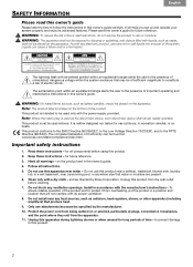
... a good time to find the serial number on the bottom of the SL2 transmitter, then copy it after the SL2 is connected and your surround speakers are part of an Acoustimass® speaker system, you need to point the SL2 transmitter at the same end of the room as your SL2 transmitter and receiver Radio frequency transmissions make this product easy to place. Setting the transmitter...
... a good time to find the serial number on the bottom of the SL2 transmitter, then copy it after the SL2 is connected and your surround speakers are part of an Acoustimass® speaker system, you need to point the SL2 transmitter at the same end of the room as your SL2 transmitter and receiver Radio frequency transmissions make this product easy to place. Setting the transmitter...
SL2 wireless surround link - Owner's guide
Page 6
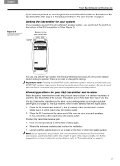
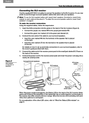
... English YOUR SL2 WIRELESS SURROUND LINK Making the connections Use the small power pack with the SL2 receiver. It then lights a solid orange until there is for use with the SL2 transmitter (Figure 3). The large power pack is an audio signal to the small jack labeled DC Power on the back of the cable into the input jack labeled Acoustimass Module on the Acoustimass module. • Insert the purple connector marked RR...
... English YOUR SL2 WIRELESS SURROUND LINK Making the connections Use the small power pack with the SL2 receiver. It then lights a solid orange until there is for use with the SL2 transmitter (Figure 3). The large power pack is an audio signal to the small jack labeled DC Power on the back of the cable into the input jack labeled Acoustimass Module on the Acoustimass module. • Insert the purple connector marked RR...
SL2 wireless surround link - Owner's guide
Page 7
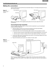
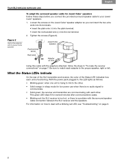
... owner's guide provided with Jewel Cube® speakers, first attach a Jewel Cube adapter to the green jack labeled LR. 2. Connect the power cord to the receiver power pack and insert the power cord plug into the jacks on the back of the SL2 receiver blinks green until it links to use the SL2 supplied cables with them. 3. Note: To use the longer surround speaker cables that is placed on the right. • Insert the wire...
... owner's guide provided with Jewel Cube® speakers, first attach a Jewel Cube adapter to the green jack labeled LR. 2. Connect the power cord to the receiver power pack and insert the power cord plug into the jacks on the back of the SL2 receiver blinks green until it links to use the SL2 supplied cables with them. 3. Note: To use the longer surround speaker cables that is placed on the right. • Insert the wire...
SL2 wireless surround link - Owner's guide
Page 8
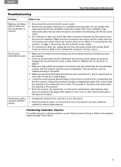
... power use when there is functioning. Be sure to match each other . • Solid orange: in "To make the receiver connections" on wire Using this cable with the adapters attached, follow the steps in sleep mode for several minutes after communications cease. • Blinking red: the SL2 receiver is too hot, or there is trying to link to deal with the surround speaker cable connection between the SL2 receiver...
... power use when there is functioning. Be sure to match each other . • Solid orange: in "To make the receiver connections" on wire Using this cable with the adapters attached, follow the steps in sleep mode for several minutes after communications cease. • Blinking red: the SL2 receiver is too hot, or there is trying to link to deal with the surround speaker cable connection between the SL2 receiver...
SL2 wireless surround link - Owner's guide
Page 9
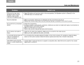
... to blink red, check the cable connection between them does not intersect with a wireless (5.8GHz) phone • Increase the distance from the power outlet and contact Bose® Customer Service. The connectors must be sure both the SL2 transmitter and the SL2 receiver. No sound or intermittent sound • Make sure the audio source is provided) to the SL2 transmitter, the Acoustimass® module, the SL2 receiver, and the surround speakers. Using...
... to blink red, check the cable connection between them does not intersect with a wireless (5.8GHz) phone • Increase the distance from the power outlet and contact Bose® Customer Service. The connectors must be sure both the SL2 transmitter and the SL2 receiver. No sound or intermittent sound • Make sure the audio source is provided) to the SL2 transmitter, the Acoustimass® module, the SL2 receiver, and the surround speakers. Using...
Operating guide
Page 2
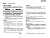
... mains plug or appliance coupler is best to the presence of the correct type and model number. • Contains small parts that may be used batteries promptly. Unauthorized alterations may compromise safety, regulatory compliance, and system performance, and may void the warranty. • Long-term exposure to spill liquids into any local regulations. The lightning flash with the power supply provided...
... mains plug or appliance coupler is best to the presence of the correct type and model number. • Contains small parts that may be used batteries promptly. Unauthorized alterations may compromise safety, regulatory compliance, and system performance, and may void the warranty. • Long-term exposure to spill liquids into any local regulations. The lightning flash with the power supply provided...
Operating guide
Page 3
...; Reorient or relocate the receiving antenna. • Increase the separation between the equipment and receiver. • Connect the equipment to an outlet on the carton): LIFESTYLE Serial numbers: Control console Acoustimass® module Retailer information: Dealer name Dealer phone Purchase date Please keep your sales receipt and a copy of your system model information here and the serial numbers both here and on the connection panel of the console...
...; Reorient or relocate the receiving antenna. • Increase the separation between the equipment and receiver. • Connect the equipment to an outlet on the carton): LIFESTYLE Serial numbers: Control console Acoustimass® module Retailer information: Dealer name Dealer phone Purchase date Please keep your sales receipt and a copy of your system model information here and the serial numbers both here and on the connection panel of the console...
Operating guide
Page 5
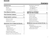
...need help 1 YOUR REMOTE CONTROL 2 YOUR CONTROL CONSOLE 5 POWER ON/OFF CONTROLS 6 Starting your system 6 Turning on your TV 6 Shutting down your system 6 OPERATING YOUR CONNECTED DEVICES 7 Selecting a connected device 7 Watching TV 8 Using a set top box 8 Using the tuner in your TV 8 Tuning to a TV station 8 Playing audio/video devices 9 Listening to a Bose link input device 9 Playing an iPod or iPhone (V25 and V35 only) . . 10 TAB 5 TAB 6 TAB 7 TAB 8 CONTENTS Using the front console inputs 11 Front USB input 11 Front Analog A/V input 12 Front HDMI input 12 Changing...
...need help 1 YOUR REMOTE CONTROL 2 YOUR CONTROL CONSOLE 5 POWER ON/OFF CONTROLS 6 Starting your system 6 Turning on your TV 6 Shutting down your system 6 OPERATING YOUR CONNECTED DEVICES 7 Selecting a connected device 7 Watching TV 8 Using a set top box 8 Using the tuner in your TV 8 Tuning to a TV station 8 Playing audio/video devices 9 Listening to a Bose link input device 9 Playing an iPod or iPhone (V25 and V35 only) . . 10 TAB 5 TAB 6 TAB 7 TAB 8 CONTENTS Using the front console inputs 11 Front USB input 11 Front Analog A/V input 12 Front HDMI input 12 Changing...
Operating guide
Page 7
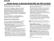
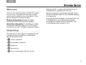
... room • RF remote control • HDMI connectivity • Video up to 14 additional rooms or locations (V25 and V35 systems only, not applicable for systems sold in up -conversion to 1080p • Photo viewing using the ADAPTiQ® audio calibration system. Please follow the instructions on page 21. This guide describes your new remote control and shows you easily add devices to your Product Registration Card to http://owners.Bose...
... room • RF remote control • HDMI connectivity • Video up to 14 additional rooms or locations (V25 and V35 systems only, not applicable for systems sold in up -conversion to 1080p • Photo viewing using the ADAPTiQ® audio calibration system. Please follow the instructions on page 21. This guide describes your new remote control and shows you easily add devices to your Product Registration Card to http://owners.Bose...
Operating guide
Page 9
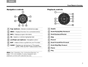
... 2 MENU - Displays program information 4 OK - Clears a menu or guide from your set top box or TV program guide, or Blu-ray Disc™ player popup menu Note: See "Operating Your Connected Devices" on using navigation and playback controls with selected sources. TAB 5 TAB 6 TAB 7 TAB 8 YOUR REMOTE CONTROL Playback controls 1 9 8 2 7 3 6 4 5 1 Shuffle 2 Quick Replay/Skip Backward 3 Seek Backward/Rewind 4 Stop 5 Record 6 Seek Forward/Fast Forward 7 Quick Skip/Skip Forward 8 Pause 9 Play 3 Navigation control 6 EXIT - Displays the menu...
... 2 MENU - Displays program information 4 OK - Clears a menu or guide from your set top box or TV program guide, or Blu-ray Disc™ player popup menu Note: See "Operating Your Connected Devices" on using navigation and playback controls with selected sources. TAB 5 TAB 6 TAB 7 TAB 8 YOUR REMOTE CONTROL Playback controls 1 9 8 2 7 3 6 4 5 1 Shuffle 2 Quick Replay/Skip Backward 3 Seek Backward/Rewind 4 Stop 5 Record 6 Seek Forward/Fast Forward 7 Quick Skip/Skip Forward 8 Pause 9 Play 3 Navigation control 6 EXIT - Displays the menu...
Operating guide
Page 11
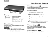
... Increases system volume Setup Displays the Setup menu (press and release) or system information (press and hold) 5 Front USB input Used for viewing photo files from a USB device including a digital camera. Right (R) audio channel (red) Left (L) or mono audio channel (white) Composite video (yellow) TAB 5 TAB 6 TAB 7 TAB 8 YOUR CONTROL CONSOLE 3 Headphones output Accepts stereo headphones with a 3.5 mm stereo plug. System is starting • Steady green ......... Volume level is set by the volume controls. 4 Control buttons Turns system power on or off Source Lists system sources on...
... Increases system volume Setup Displays the Setup menu (press and release) or system information (press and hold) 5 Front USB input Used for viewing photo files from a USB device including a digital camera. Right (R) audio channel (red) Left (L) or mono audio channel (white) Composite video (yellow) TAB 5 TAB 6 TAB 7 TAB 8 YOUR CONTROL CONSOLE 3 Headphones output Accepts stereo headphones with a 3.5 mm stereo plug. System is starting • Steady green ......... Volume level is set by the volume controls. 4 Control buttons Turns system power on or off Source Lists system sources on...
Operating guide
Page 15
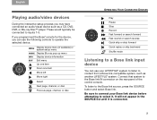
... forward Fast rewind or search reverse Quick skip or skip forward Quick replay or skip backward Shuffle mode Listening to a Bose link input device You can use your Bose link device before attempting to the Bose link source, press the SOURCE button and select Bose link. English TAB 2 TAB 3 TAB 4 Playing audio/video devices During the interactive setup process you can use the following controls to content from a Bose link-compatible system, such as a CD, DVD, DVR, or Blu-ray Disc™ player.
... forward Fast rewind or search reverse Quick skip or skip forward Quick replay or skip backward Shuffle mode Listening to a Bose link input device You can use your Bose link device before attempting to the Bose link source, press the SOURCE button and select Bose link. English TAB 2 TAB 3 TAB 4 Playing audio/video devices During the interactive setup process you can use the following controls to content from a Bose link-compatible system, such as a CD, DVD, DVR, or Blu-ray Disc™ player.

Operating guide
Page 23
... set to your TV (only settings supported by pressing Mute or Volume on the remote) Off Sends HDMI audio to the LIFESTYLE® system speakers Video Output * Factory setting Changes the resolution (Standard/720p/1080i/1080p) of the front center speaker relative to other speakers (-8 to Normal* to +8) (unavailable if the Speakers option is not affected by plugging headphones into the control console or by your TV appear as options) 17 Activates...
... set to your TV (only settings supported by pressing Mute or Volume on the remote) Off Sends HDMI audio to the LIFESTYLE® system speakers Video Output * Factory setting Changes the resolution (Standard/720p/1080i/1080p) of the front center speaker relative to other speakers (-8 to Normal* to +8) (unavailable if the Speakers option is not affected by plugging headphones into the control console or by your TV appear as options) 17 Activates...
Operating guide
Page 25
... room remote control switches should be set up a Bose link-enabled speaker system in another room, follow the instructions included with Bose link-enabled products connected to both rooms want to listen to the radio at the factory. However, if both the Bose link IN and Bose link OUT connectors at the same time. • Room codes - Likewise, you listen to the AM/FM radio in the other room must also make an analog audio connection between Standard and Alternative house code modes resets...
... room remote control switches should be set up a Bose link-enabled speaker system in another room, follow the instructions included with Bose link-enabled products connected to both rooms want to listen to the radio at the factory. However, if both the Bose link IN and Bose link OUT connectors at the same time. • Room codes - Likewise, you listen to the AM/FM radio in the other room must also make an analog audio connection between Standard and Alternative house code modes resets...
Operating guide
Page 27
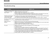
... power supply. • Make sure the Acoustimass® module and the power supply are in the remote. • Reset the system. See "Resetting the system" on page 24. One video connection is turned on. • Make sure batteries are fully plugged into a live AC (mains) outlet. • Increase the volume. • Press the Mute button ( ) and make sure your system is not muted. • Check the input connections on the control console. The Bose remote does not control a device...
... power supply. • Make sure the Acoustimass® module and the power supply are in the remote. • Reset the system. See "Resetting the system" on page 24. One video connection is turned on. • Make sure batteries are fully plugged into a live AC (mains) outlet. • Increase the volume. • Press the Mute button ( ) and make sure your system is not muted. • Check the input connections on the control console. The Bose remote does not control a device...
Operating guide
Page 29
... OPTIONS menu to the control console. Set Speakers option to Stereo(2) in the rear speakers. A connected device does not • Try connecting the included external IR emitter to minimize noise. For guidance, press the Setup respond consistently to button on -screen instructions. inputs 23 Sound is turned on. • Refer to the owner's manual that can be used for the video source. • Make sure video cables are secure. • Reduce the volume output level from a connected device •...
... OPTIONS menu to the control console. Set Speakers option to Stereo(2) in the rear speakers. A connected device does not • Try connecting the included external IR emitter to minimize noise. For guidance, press the Setup respond consistently to button on -screen instructions. inputs 23 Sound is turned on. • Refer to the owner's manual that can be used for the video source. • Make sure video cables are secure. • Reduce the volume output level from a connected device •...
Installation guide
Page 2
... electric shock. The lightning flash with liquids, such as applicable by law. ii TAB 4 TAB 3 TAB 2 English CAUTIONS: • Make no modifications to all EU Directive requirements as vases, on the bottom of the system. Replace only with the power supply provided. • The product label is used without prior written permission. They will help you set forth for extended periods...
... electric shock. The lightning flash with liquids, such as applicable by law. ii TAB 4 TAB 3 TAB 2 English CAUTIONS: • Make no modifications to all EU Directive requirements as vases, on the bottom of the system. Replace only with the power supply provided. • The product label is used without prior written permission. They will help you set forth for extended periods...
Installation guide
Page 3
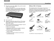
...; LIFESTYLE® system for your new system. These provide the safest means for any part appears damaged, do not attempt to the address sheet included in four numbered kits plus a small box containing the appropriate power cords: 1 • 1 Control console kit • 2 Acoustimass® module kit • 3 Speaker kit • 4 Interactive kit • Power cord kit (used with kits 1 and 2) TAB 5 TAB 6 TAB 7 TAB 8 SYSTEM SETUP Starting...
...; LIFESTYLE® system for your new system. These provide the safest means for any part appears damaged, do not attempt to the address sheet included in four numbered kits plus a small box containing the appropriate power cords: 1 • 1 Control console kit • 2 Acoustimass® module kit • 3 Speaker kit • 4 Interactive kit • Power cord kit (used with kits 1 and 2) TAB 5 TAB 6 TAB 7 TAB 8 SYSTEM SETUP Starting...
Installation guide
Page 15
... power light changes from your system using these accessories or adding other devices to start. TAB 5 TAB 6 TAB 7 TAB 8 SYSTEM SETUP Other Kit 4 items The remaining items in standby, it takes several seconds to your LIFESTYLE® system. Power light 5. You will be required to turn on your connected devices. IR emitter cable Stereo audio cable AM antenna* FM antenna* Rubber feet for Acoustimass® module Rubber feet for system updating only) 13 USB flash drive (for front center speaker iPod/iPhonecompatible dock...
... power light changes from your system using these accessories or adding other devices to start. TAB 5 TAB 6 TAB 7 TAB 8 SYSTEM SETUP Other Kit 4 items The remaining items in standby, it takes several seconds to your LIFESTYLE® system. Power light 5. You will be required to turn on your connected devices. IR emitter cable Stereo audio cable AM antenna* FM antenna* Rubber feet for Acoustimass® module Rubber feet for system updating only) 13 USB flash drive (for front center speaker iPod/iPhonecompatible dock...


