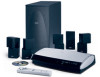
The Bose® Lifestyle® amplifier - Owner's guide
Page 6
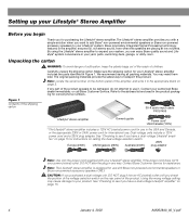
...of suffocation, keep the plastic bags out of the reach of the shipping carton 30-ft audio input cable PN197406 Lifestyle® stereo amplifier Owner's guide Power cord* USA/Canada (120V) * The Lifestyle® stereo amplifier includes a 120V AC (mains) power cord for use it...switch. 230V Europe (230V) UK/Singapore (230V) Australia (240V) plug adaptor Note: Use only the power cord supplied with Bose non-powered environmental speakers or Bose non-powered accessory speakers ONLY. Note: Locate the serial number on page 3. Using the wrong voltage setting may need them ...
...of suffocation, keep the plastic bags out of the reach of the shipping carton 30-ft audio input cable PN197406 Lifestyle® stereo amplifier Owner's guide Power cord* USA/Canada (120V) * The Lifestyle® stereo amplifier includes a 120V AC (mains) power cord for use it...switch. 230V Europe (230V) UK/Singapore (230V) Australia (240V) plug adaptor Note: Use only the power cord supplied with Bose non-powered environmental speakers or Bose non-powered accessory speakers ONLY. Note: Locate the serial number on page 3. Using the wrong voltage setting may need them ...
The Bose® Lifestyle® amplifier - Owner's guide
Page 7
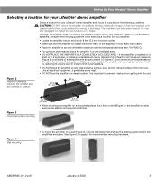
... rubber feet provide stability and prevent scratches. AM262840_00_V.pdf January 4, 2002 5 The amplifier must be situated close to either your Lifestyle® system or the accessory speakers, consider the following guidelines. If adequate ventilation is less than 104°F (45°C). • ... a location for your Lifestyle® stereo amplifier and mount it according to the following guidelines when selecting a location for your amplifier: • Locate the amplifier indoors and within the reach of the supplied 30-foot audio input cable. • Place the...
... rubber feet provide stability and prevent scratches. AM262840_00_V.pdf January 4, 2002 5 The amplifier must be situated close to either your Lifestyle® system or the accessory speakers, consider the following guidelines. If adequate ventilation is less than 104°F (45°C). • ... a location for your Lifestyle® stereo amplifier and mount it according to the following guidelines when selecting a location for your amplifier: • Locate the amplifier indoors and within the reach of the supplied 30-foot audio input cable. • Place the...
The Bose® Lifestyle® amplifier - Owner's guide
Page 9
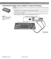
Insert the white RCA piggyback connector of the supplied cable into one end of the audio input cable into the L (left) INPUT jack. Figure 6 Cable connections between a multi-room interface and the Lifestyle® stereo amplifier Lifestyle® stereo amplifier rear panel Multi-room interface rear panel 4 Ω MINIMUM LL R L SYSTEM RR CONTROL L R +- Setting Up...
Insert the white RCA piggyback connector of the supplied cable into one end of the audio input cable into the L (left) INPUT jack. Figure 6 Cable connections between a multi-room interface and the Lifestyle® stereo amplifier Lifestyle® stereo amplifier rear panel Multi-room interface rear panel 4 Ω MINIMUM LL R L SYSTEM RR CONTROL L R +- Setting Up...
The Bose® Lifestyle® amplifier - Owner's guide
Page 11
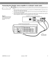
.... 3. At the other connections. 1. Figure 8 Cable connections between the Lifestyle® media center and the Lifestyle® stereo amplifier Lifestyle® SA-1 stereo amplifier rear panel Lifestyle® media center rear panel 30-ft audio input cable (supplied) AM262840_00_V.pdf January 4, 2002 9 Setting Up Your Lifestyle® Stereo Amplifier Connecting the Lifestyle® stereo amplifier to...
.... 3. At the other connections. 1. Figure 8 Cable connections between the Lifestyle® media center and the Lifestyle® stereo amplifier Lifestyle® SA-1 stereo amplifier rear panel Lifestyle® media center rear panel 30-ft audio input cable (supplied) AM262840_00_V.pdf January 4, 2002 9 Setting Up Your Lifestyle® Stereo Amplifier Connecting the Lifestyle® stereo amplifier to...
The Bose® Lifestyle® amplifier - Owner's guide
Page 13
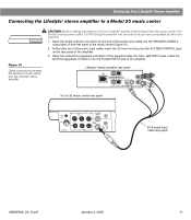
... Insert the single multi-pin connector at one end of the audio input cable into the R (right) INPUT jack of the music center (Figure 10). 2. SPEAKER OUTPUTS INPUT Model 20 music center rear panel 30-ft audio input cable (supplied) AM262840_00_V.pdf January 4, 2002 11 Insert the red ...RCA piggyback connector into the SPEAKER ZONES 2 output jack on the rear panel of the audio input cable, insert the 3.5 mm mini-plug into the L (left) INPUT jack. Lifestyle® stereo amplifier rear panel 4 Ω MINIMUM LL R L SYSTEM RR CONTROL L R +-...
... Insert the single multi-pin connector at one end of the audio input cable into the R (right) INPUT jack of the music center (Figure 10). 2. SPEAKER OUTPUTS INPUT Model 20 music center rear panel 30-ft audio input cable (supplied) AM262840_00_V.pdf January 4, 2002 11 Insert the red ...RCA piggyback connector into the SPEAKER ZONES 2 output jack on the rear panel of the audio input cable, insert the 3.5 mm mini-plug into the L (left) INPUT jack. Lifestyle® stereo amplifier rear panel 4 Ω MINIMUM LL R L SYSTEM RR CONTROL L R +-...
The Bose® Lifestyle® amplifier - Owner's guide
Page 15
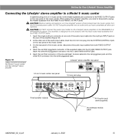
...fier into the SYSTEM CONTROL 2 jack on the rear of the amplifier (Figure 12). 2. CAUTION: DO NOT connect the audio input cable for the Lifestyle® stereo amplifier to work properly with the fixed output level available from the FIXED OUTPUT jacks. 1. Insert the red ... connected to temporarily unplug the theater speakers from the FIXED R and FIXED L OUTPUT jacks. When adding the Lifestyle® amplifier, you have completed all other end of the audio input cable, insert the 3.5 mm mini-plug into an outlet until you need to the FIXED OUTPUT jacks on the...
...fier into the SYSTEM CONTROL 2 jack on the rear of the amplifier (Figure 12). 2. CAUTION: DO NOT connect the audio input cable for the Lifestyle® stereo amplifier to work properly with the fixed output level available from the FIXED OUTPUT jacks. 1. Insert the red ... connected to temporarily unplug the theater speakers from the FIXED R and FIXED L OUTPUT jacks. When adding the Lifestyle® amplifier, you have completed all other end of the audio input cable, insert the 3.5 mm mini-plug into an outlet until you need to the FIXED OUTPUT jacks on the...

The Bose® Lifestyle® amplifier - Owner's guide
Page 18
... home theater (Lifestyle® 12 or Lifestyle® 8 systems), make sure the amplifier audio input cable is plugged into any solvents, chemicals, or cleaning solutions containing alcohol, ammonia, or abrasives. If CD or AUX is selected, check to be sure there is a CD in the product packaging for service, or contact Bose Customer Service...
... home theater (Lifestyle® 12 or Lifestyle® 8 systems), make sure the amplifier audio input cable is plugged into any solvents, chemicals, or cleaning solutions containing alcohol, ammonia, or abrasives. If CD or AUX is selected, check to be sure there is a CD in the product packaging for service, or contact Bose Customer Service...

Owner's guide
Page 39
... and install the batteries accordingly. If it is, press the Mute button on the remote control to unmute the sound. • Make sure the audio input cable is firmly seated in the media center SPEAKER ZONE 1 jack and the multi-pin connector on the remote and snap it . AM259776_01_V.pdf ... securely into operating AC wall outlets. • Be sure to select the correct source for the desired input. • Be sure the disc is placed correctly, label-side up, in the Acoustimass module AUDIO INPUT jack. • Check speaker connections. • Turn the media center off of the back of the...
... and install the batteries accordingly. If it is, press the Mute button on the remote control to unmute the sound. • Make sure the audio input cable is firmly seated in the media center SPEAKER ZONE 1 jack and the multi-pin connector on the remote and snap it . AM259776_01_V.pdf ... securely into operating AC wall outlets. • Be sure to select the correct source for the desired input. • Be sure the disc is placed correctly, label-side up, in the Acoustimass module AUDIO INPUT jack. • Check speaker connections. • Turn the media center off of the back of the...
Owner's guide
Page 41
..." jack. See "Programming your LIFESTYLE® remote to control your external...cables are not damaged and the connections are set. Media center display says: • Make sure the audio input cable... is firmly seated in the surround speakers. When you may need to connect an external IR emitter (available from any external components connected to minimize noise. Reference Problem What to do FM sound is distorted • Adjust antenna position to "Detected TV Power: On". LIFESTYLE...® remote does not control TV, VCR, and/ or cable/satellite...
..." jack. See "Programming your LIFESTYLE® remote to control your external...cables are not damaged and the connections are set. Media center display says: • Make sure the audio input cable... is firmly seated in the surround speakers. When you may need to connect an external IR emitter (available from any external components connected to minimize noise. Reference Problem What to do FM sound is distorted • Adjust antenna position to "Detected TV Power: On". LIFESTYLE...® remote does not control TV, VCR, and/ or cable/satellite...
Installation guide
Page 5
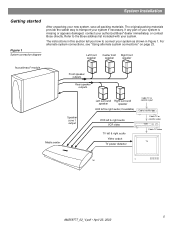
... surround Right surround speaker speaker AUX left & right audio (if available) Cable TV or satellite input Cable/satellite box VCR left & right audio VCR video TV left & right audio Video output TV power detector Cable TV or satellite video VCR Cable TV video TV TM 5 AM259777_02_V.pdf • April...section tell you how to transport your authorized Bose® dealer immediately, or contact Bose directly. For alternate system connections, see "Using alternate system connections" on page 23. The instructions in Figure 1. Refer to the Bose address list included with your new system, ...
... surround Right surround speaker speaker AUX left & right audio (if available) Cable TV or satellite input Cable/satellite box VCR left & right audio VCR video TV left & right audio Video output TV power detector Cable TV or satellite video VCR Cable TV video TV TM 5 AM259777_02_V.pdf • April...section tell you how to transport your authorized Bose® dealer immediately, or contact Bose directly. For alternate system connections, see "Using alternate system connections" on page 23. The instructions in Figure 1. Refer to the Bose address list included with your new system, ...

Installation guide
Page 6
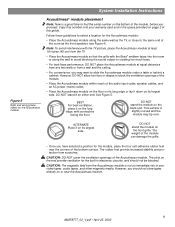
... accessories The following items are included with your system. Figure 2 Cables and accessories included with your system L R Surround speaker cables Front speaker cables Stereo audio cable Video cable (6 ft) S-Video cable Audio input cable Component video adapter 1 Mounting strip TV on/off detector Rubber feet for Acoustimass® module OR Rubber feet for cube speakers Batteries Remote control AM ...
... accessories The following items are included with your system. Figure 2 Cables and accessories included with your system L R Surround speaker cables Front speaker cables Stereo audio cable Video cable (6 ft) S-Video cable Audio input cable Component video adapter 1 Mounting strip TV on/off detector Rubber feet for Acoustimass® module OR Rubber feet for cube speakers Batteries Remote control AM ...
Installation guide
Page 9
... your warranty card and in electronic circuitry, and should not store tapes directly on its long edge or lay it on the bottom of the audio input cable, speaker cables, and an AC power (mains) outlet. • Place the Acoustimass module on the floor on its largest side. CAUTION: DO NOT... cover the ventilation openings of this guide. However, you proceed. Copy that the grille with the Bose® emblem faces into the room or along the same...
... your warranty card and in electronic circuitry, and should not store tapes directly on its long edge or lay it on the bottom of the audio input cable, speaker cables, and an AC power (mains) outlet. • Place the Acoustimass module on the floor on its largest side. CAUTION: DO NOT... cover the ventilation openings of this guide. However, you proceed. Copy that the grille with the Bose® emblem faces into the room or along the same...
Installation guide
Page 10
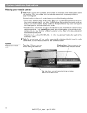
...your components, see your system. • Place the media center within 30 feet (9.1 m) of the Acoustimass® module (the length of the audio input cable). Note: For convenience, until your system is a good time to find the serial number on page 2 of the CD tray cover. Figure... 6 Front features of the media center, before you need additional audio and/or video cables to allow for you allow enough room to the Bose address list included with your dealer or call Bose® customer service. System Installation Instructions Placing your media center Note: Now...
...your components, see your system. • Place the media center within 30 feet (9.1 m) of the Acoustimass® module (the length of the audio input cable). Note: For convenience, until your system is a good time to find the serial number on page 2 of the CD tray cover. Figure... 6 Front features of the media center, before you need additional audio and/or video cables to allow for you allow enough room to the Bose address list included with your dealer or call Bose® customer service. System Installation Instructions Placing your media center Note: Now...

Installation guide
Page 12
... Left Right To FRONT L To FRONT C To FRONT R To SURROUND L To SURROUND R AUDIO INPUT OUTPUTS TO CUBE SPEAKERS FRONT SURROUND L C L R R POWER 100-120/200-240V AC 50/60 Hz 350W MAX. 12 AM259777_02_V.pdf • April 23, 2002 Surround speaker cables have blue RCA connectors at one end, with L (left ) or R (right) molded...
... Left Right To FRONT L To FRONT C To FRONT R To SURROUND L To SURROUND R AUDIO INPUT OUTPUTS TO CUBE SPEAKERS FRONT SURROUND L C L R R POWER 100-120/200-240V AC 50/60 Hz 350W MAX. 12 AM259777_02_V.pdf • April 23, 2002 Surround speaker cables have blue RCA connectors at one end, with L (left ) or R (right) molded...

Installation guide
Page 13
...the Acoustimass module. Figure 10 Acoustimass module connection to the media center with the audio input cable (Figure 10). When properly connected, it should lock in place. Audio input cable Note: Press tab to the cable connection at side facing up a second listening zone" on page 25 for ... the Acoustimass module. CAUTION: Do not place strain on the audio input cable, especially on the connector. 13 AM259777_02_V.pdf • April 23, 2002 Note: Be sure that each connector is fully inserted into the AUDIO INPUT jack on the other end of the media center. 2. Note...
...the Acoustimass module. Figure 10 Acoustimass module connection to the media center with the audio input cable (Figure 10). When properly connected, it should lock in place. Audio input cable Note: Press tab to the cable connection at side facing up a second listening zone" on page 25 for ... the Acoustimass module. CAUTION: Do not place strain on the audio input cable, especially on the connector. 13 AM259777_02_V.pdf • April 23, 2002 Note: Be sure that each connector is fully inserted into the AUDIO INPUT jack on the other end of the media center. 2. Note...

Installation guide
Page 14
.... To connect to this service, contact your home. Connecting to a cable radio provider Some cable TV providers make FM radio signals available through the cable service to the external FM jack on a wall, follow the instructions ...cable TV provider for the AM and FM antennas AM antenna lead FM dipole antenna lead TV SENSOR IR EMITTER SERIAL DATA 33V DC POWER 1.1A RECORD TAPE AUX VCR TV AM L L L L L FM 75 ANTENNA 1 OPTICAL OPTICAL R R R R R VIDEO INPUTS COMPOSITE S-VIDEO 2 SPEAKER ZONES INPUT OUTPUT DIGITAL AUDIO OUTPUTS DIGITAL DIGITAL DIGITAL AUDIO INPUTS...
.... To connect to this service, contact your home. Connecting to a cable radio provider Some cable TV providers make FM radio signals available through the cable service to the external FM jack on a wall, follow the instructions ...cable TV provider for the AM and FM antennas AM antenna lead FM dipole antenna lead TV SENSOR IR EMITTER SERIAL DATA 33V DC POWER 1.1A RECORD TAPE AUX VCR TV AM L L L L L FM 75 ANTENNA 1 OPTICAL OPTICAL R R R R R VIDEO INPUTS COMPOSITE S-VIDEO 2 SPEAKER ZONES INPUT OUTPUT DIGITAL AUDIO OUTPUTS DIGITAL DIGITAL DIGITAL AUDIO INPUTS...

Installation guide
Page 15
... connections These connections will need to the L and R TV audio inputs on the rear panel of your TV (Figure 12). See Figure 12. 4 Figure 12 Media center-to-TV video and audio connections Making audio connections Using the supplied stereo audio cable, connect the left (L) and right (R) audio outputs on the rear panel of your TV to...
... connections These connections will need to the L and R TV audio inputs on the rear panel of your TV (Figure 12). See Figure 12. 4 Figure 12 Media center-to-TV video and audio connections Making audio connections Using the supplied stereo audio cable, connect the left (L) and right (R) audio outputs on the rear panel of your TV to...
Installation guide
Page 16
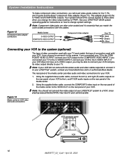
... cables. If you choose to connect it to your LIFESTYLE® system, contact your VCR to -VCR video and audio connections TV SENSOR IR EMITTER SERIAL DATA 33V DC POWER 1.1A RECORD TAPE AUX VCR TV AM L L L L L FM 75 ANTENNA 1 OPTICAL OPTICAL R R R R R VIDEO INPUTS COMPOSITE S-VIDEO 2 SPEAKER ZONES INPUT OUTPUT DIGITAL AUDIO OUTPUTS DIGITAL DIGITAL DIGITAL AUDIO INPUTS...
... cables. If you choose to connect it to your LIFESTYLE® system, contact your VCR to -VCR video and audio connections TV SENSOR IR EMITTER SERIAL DATA 33V DC POWER 1.1A RECORD TAPE AUX VCR TV AM L L L L L FM 75 ANTENNA 1 OPTICAL OPTICAL R R R R R VIDEO INPUTS COMPOSITE S-VIDEO 2 SPEAKER ZONES INPUT OUTPUT DIGITAL AUDIO OUTPUTS DIGITAL DIGITAL DIGITAL AUDIO INPUTS...
Installation guide
Page 17
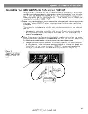
... the L and R AUX audio inputs on the rear panel of the media center provides audio and video connections for use with your cable/satellite box, if you connected your TV to the S-VIDEO OUTPUT, connect your cable/satellite box to your LIFESTYLE® system, contact your cable/satellite box to -cable/satellite box video and audio connections (if VCR...
... the L and R AUX audio inputs on the rear panel of the media center provides audio and video connections for use with your cable/satellite box, if you connected your TV to the S-VIDEO OUTPUT, connect your cable/satellite box to your LIFESTYLE® system, contact your cable/satellite box to -cable/satellite box video and audio connections (if VCR...
Installation guide
Page 25
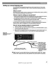
...speakers, remote controls, cables, and adapters for setting up a second zone? • A Bose® powered speaker system that have a mini-DIN connector marked "FIX". Cables marked "VAR" should not be connected (special adapter required). • The appropriate LIFESTYLE® system cable to connect the zone ... AUX) to operate the zone 2 sound. Connect the audio input cable from one or two sound sources (such as zone 1. Each listening area, whether a room or a group of the media center. • A second LIFESTYLE® system remote control to two different listening zones at...
...speakers, remote controls, cables, and adapters for setting up a second zone? • A Bose® powered speaker system that have a mini-DIN connector marked "FIX". Cables marked "VAR" should not be connected (special adapter required). • The appropriate LIFESTYLE® system cable to connect the zone ... AUX) to operate the zone 2 sound. Connect the audio input cable from one or two sound sources (such as zone 1. Each listening area, whether a room or a group of the media center. • A second LIFESTYLE® system remote control to two different listening zones at...


