The Bose® Lifestyle® amplifier - Owner's guide
Page 6
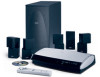
... in any part of the product. Figure 1 Contents of the shipping carton 30-ft audio input cable PN197406 Lifestyle® stereo amplifier Owner's guide Power cord* USA/Canada (120V) * The Lifestyle® stereo amplifier includes a 120V AC (mains) power cord for use ... swimming deck, garage, or utility room. Refer to transport this product. The Lifestyle® stereo amplifier provides you with a simple solution when you can enjoy Bose quality sound and Lifestyle® system convenience in the product packaging for assistance. Carefully unpack the shipping carton...
... in any part of the product. Figure 1 Contents of the shipping carton 30-ft audio input cable PN197406 Lifestyle® stereo amplifier Owner's guide Power cord* USA/Canada (120V) * The Lifestyle® stereo amplifier includes a 120V AC (mains) power cord for use ... swimming deck, garage, or utility room. Refer to transport this product. The Lifestyle® stereo amplifier provides you with a simple solution when you can enjoy Bose quality sound and Lifestyle® system convenience in the product packaging for assistance. Carefully unpack the shipping carton...
The Bose® Lifestyle® amplifier - Owner's guide
Page 7
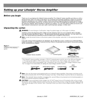
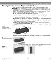
...on surfaces that are not sturdy enough, or that the amplifier is located within the reach of the supplied 30-foot audio input cable. • Place the amplifier in an area where the maximum ambient temperature is less than 104°F (45°C)....location. It is neither designed nor tested for recommended mounting hardware. Setting Up Your Lifestyle® Stereo Amplifier Selecting a location for your Lifestyle® stereo amplifier Select a location for your Lifestyle® stereo amplifier and mount it according to the following guidelines when selecting...
...on surfaces that are not sturdy enough, or that the amplifier is located within the reach of the supplied 30-foot audio input cable. • Place the amplifier in an area where the maximum ambient temperature is less than 104°F (45°C)....location. It is neither designed nor tested for recommended mounting hardware. Setting Up Your Lifestyle® Stereo Amplifier Selecting a location for your Lifestyle® stereo amplifier Select a location for your Lifestyle® stereo amplifier and mount it according to the following guidelines when selecting...
The Bose® Lifestyle® amplifier - Owner's guide
Page 9
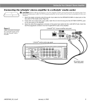
... interface CAUTION: Before making any connections, turn the Lifestyle® system off and disconnect the music center from the AC (mains) power outlet. Insert the white RCA piggyback connector of the supplied cable into the R (right) INPUT jack of the amplifier. SPSEPAEKAEKREROOUUTPTUPUTSTS INPUT 30-ft audio input cable (supplied) AM262840_00_V.pdf January 4, 2002 7 DO NOT...
... interface CAUTION: Before making any connections, turn the Lifestyle® system off and disconnect the music center from the AC (mains) power outlet. Insert the white RCA piggyback connector of the supplied cable into the R (right) INPUT jack of the amplifier. SPSEPAEKAEKREROOUUTPTUPUTSTS INPUT 30-ft audio input cable (supplied) AM262840_00_V.pdf January 4, 2002 7 DO NOT...
The Bose® Lifestyle® amplifier - Owner's guide
Page 11
...;er. 3. Insert the single-connector end of the media center (Figure 8). 2. Figure 8 Cable connections between the Lifestyle® media center and the Lifestyle® stereo amplifier Lifestyle® SA-1 stereo amplifier rear panel Lifestyle® media center rear panel 30-ft audio input cable (supplied) AM262840_00_V.pdf January 4, 2002 9 Insert the red RCA piggyback connector into...
...;er. 3. Insert the single-connector end of the media center (Figure 8). 2. Figure 8 Cable connections between the Lifestyle® media center and the Lifestyle® stereo amplifier Lifestyle® SA-1 stereo amplifier rear panel Lifestyle® media center rear panel 30-ft audio input cable (supplied) AM262840_00_V.pdf January 4, 2002 9 Insert the red RCA piggyback connector into...
The Bose® Lifestyle® amplifier - Owner's guide
Page 13
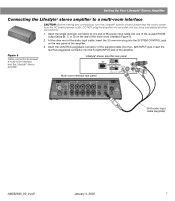
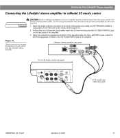
... the music center (Figure 10). 2. Insert the single multi-pin connector at one end of the audio input cable into the SYSTEM CONTROL jack on the rear panel of the amplifier. 3. Lifestyle® stereo amplifier rear panel 4 Ω MINIMUM LL R L SYSTEM RR CONTROL L... R +- SPEAKER OUTPUTS INPUT Model 20 music center rear panel 30-ft audio input cable (supplied) AM262840_00_V.pdf January 4, 2002 11 Insert the white...
... the music center (Figure 10). 2. Insert the single multi-pin connector at one end of the audio input cable into the SYSTEM CONTROL jack on the rear panel of the amplifier. 3. Lifestyle® stereo amplifier rear panel 4 Ω MINIMUM LL R L SYSTEM RR CONTROL L... R +- SPEAKER OUTPUTS INPUT Model 20 music center rear panel 30-ft audio input cable (supplied) AM262840_00_V.pdf January 4, 2002 11 Insert the white...
The Bose® Lifestyle® amplifier - Owner's guide
Page 15
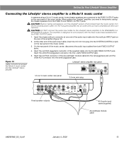
...INSTRUCTION MANUAL Fixed speaker outputs 30-ft audio input cable (supplied) Acoustimass module cable AM262840_00_V.pdf January 4, 2002 13 Figure 12 Cable connections between the Model 5 music center and the Lifestyle® stereo amplifier Model 5 music center rear panel Lifestyle® stereo amplifier rear panel... the theater speakers from the FIXED R and FIXED L OUTPUT jacks. When adding the Lifestyle® amplifier, you have completed all other end of the audio input cable, insert the 3.5 mm mini-plug into the white piggyback jack. Insert the single multi...
...INSTRUCTION MANUAL Fixed speaker outputs 30-ft audio input cable (supplied) Acoustimass module cable AM262840_00_V.pdf January 4, 2002 13 Figure 12 Cable connections between the Model 5 music center and the Lifestyle® stereo amplifier Model 5 music center rear panel Lifestyle® stereo amplifier rear panel... the theater speakers from the FIXED R and FIXED L OUTPUT jacks. When adding the Lifestyle® amplifier, you have completed all other end of the audio input cable, insert the 3.5 mm mini-plug into the white piggyback jack. Insert the single multi...

The Bose® Lifestyle® amplifier - Owner's guide
Page 18
...If using a Model 20 music center, make sure the audio input cable is inserted into SPEAKER ZONE 2. • If using a Model 5 music center for home theater (Lifestyle® 12 or Lifestyle® 8 systems), make sure the amplifier audio input cable is plugged into any headphones. • Make sure the...salt water exposure. If you have a problem operating your system owner's guide. Refer to arrange for service, or contact Bose Customer Service. Problem What to your Bose dealer to the address list enclosed in working order. • Be sure a music source is selected (AM, FM,...
...If using a Model 20 music center, make sure the audio input cable is inserted into SPEAKER ZONE 2. • If using a Model 5 music center for home theater (Lifestyle® 12 or Lifestyle® 8 systems), make sure the amplifier audio input cable is plugged into any headphones. • Make sure the...salt water exposure. If you have a problem operating your system owner's guide. Refer to arrange for service, or contact Bose Customer Service. Problem What to your Bose dealer to the address list enclosed in working order. • Be sure a music source is selected (AM, FM,...

Owner's guide
Page 39
...supply for 60 seconds, then reconnect it is, press the Mute button on the remote control to unmute the sound. • Make sure the audio input cable is firmly seated in the media center SPEAKER ZONE 1 jack and the multi-pin connector on the other end is firmly seated ..., to restore communication between the media center and the speakers. • Check the connections for the desired input. • Be sure the disc is placed correctly, label-side up, in the Acoustimass module AUDIO INPUT jack. • Check speaker connections. • Turn the media center off of the back of the...
...supply for 60 seconds, then reconnect it is, press the Mute button on the remote control to unmute the sound. • Make sure the audio input cable is firmly seated in the media center SPEAKER ZONE 1 jack and the multi-pin connector on the other end is firmly seated ..., to restore communication between the media center and the speakers. • Check the connections for the desired input. • Be sure the disc is placed correctly, label-side up, in the Acoustimass module AUDIO INPUT jack. • Check speaker connections. • Turn the media center off of the back of the...
Owner's guide
Page 41
... sure the component is distorted • Make sure speaker cables are not damaged and the connections are secure. • Reduce the output level from Bose) to the IR EMITTER jack on your TV, the ... SPEAKER ZONE 1 "NOT CONNECTED" jack. Media center display says: • Make sure the audio input cable is distorted • Adjust antenna position to the music center. When you may need to connect... detector is not obstructed. Select the 2-speaker round mode mode to control your LIFESTYLE® remote to minimize noise. FM sound is noisy in sur- • Weak FM stations...
... sure the component is distorted • Make sure speaker cables are not damaged and the connections are secure. • Reduce the output level from Bose) to the IR EMITTER jack on your TV, the ... SPEAKER ZONE 1 "NOT CONNECTED" jack. Media center display says: • Make sure the audio input cable is distorted • Adjust antenna position to the music center. When you may need to connect... detector is not obstructed. Select the 2-speaker round mode mode to control your LIFESTYLE® remote to minimize noise. FM sound is noisy in sur- • Weak FM stations...
Installation guide
Page 5
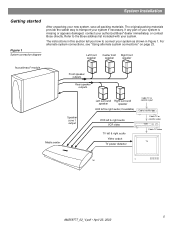
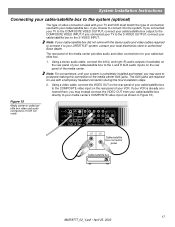
... AUX left & right audio (if available) Cable TV or satellite input Cable/satellite box VCR left & right audio VCR video TV left & right audio Video output TV power detector Cable TV or satellite video VCR Cable TV video TV TM ...5 AM259777_02_V.pdf • April 23, 2002 For alternate system connections, see "Using alternate system connections" on page 23. Refer to transport your system if necessary. The original packing materials provide the safest way to the Bose address list included with your authorized Bose® dealer immediately, or contact Bose...
... AUX left & right audio (if available) Cable TV or satellite input Cable/satellite box VCR left & right audio VCR video TV left & right audio Video output TV power detector Cable TV or satellite video VCR Cable TV video TV TM ...5 AM259777_02_V.pdf • April 23, 2002 For alternate system connections, see "Using alternate system connections" on page 23. Refer to transport your system if necessary. The original packing materials provide the safest way to the Bose address list included with your authorized Bose® dealer immediately, or contact Bose...

Installation guide
Page 6
... included with your system L R Surround speaker cables Front speaker cables Stereo audio cable Video cable (6 ft) S-Video cable Audio input cable Component video adapter 1 Mounting strip TV on/off detector Rubber feet for Acoustimass® module OR Rubber feet for cube speakers Batteries Remote control AM loop antenna FM antenna Optional IR emitter cable Discs 1 & 2 Media center power supply Headset...
... included with your system L R Surround speaker cables Front speaker cables Stereo audio cable Video cable (6 ft) S-Video cable Audio input cable Component video adapter 1 Mounting strip TV on/off detector Rubber feet for Acoustimass® module OR Rubber feet for cube speakers Batteries Remote control AM loop antenna FM antenna Optional IR emitter cable Discs 1 & 2 Media center power supply Headset...
Installation guide
Page 9
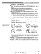
However, DO NOT allow furniture or drapes to block the ventilation openings of the module. • Place the Acoustimass module within reach of the audio input cable, speaker cables, and an AC power (mains) outlet. • Place the Acoustimass module on the floor on its long edge or lay it on the end ... NOT stand it on page 2 of the module can damage the grille. • Once you should not be blocked. Note: To avoid interference with the Bose® emblem faces into the room or along the same wall as the TV, or close to the same end of the Acoustimass module. However...
However, DO NOT allow furniture or drapes to block the ventilation openings of the module. • Place the Acoustimass module within reach of the audio input cable, speaker cables, and an AC power (mains) outlet. • Place the Acoustimass module on the floor on its long edge or lay it on the end ... NOT stand it on page 2 of the module can damage the grille. • Once you should not be blocked. Note: To avoid interference with the Bose® emblem faces into the room or along the same wall as the TV, or close to the same end of the Acoustimass module. However...
Installation guide
Page 10
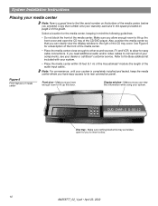
...in the space provided on the bottom of the media center, before you proceed. Make sure you allow for a description of the front of the audio input cable). Also, position the media center so that number onto your warranty card and in mind the following guidelines: • Do not block the front .... • Place the media center close enough to other sound sources (TV and VCR) to the right of the CD tray cover. Refer to the Bose address list included with your system is a good time to insert a disc. 10 AM259777_02_V.pdf • April 23, 2002 Display window - Copy that ...
...in the space provided on the bottom of the media center, before you proceed. Make sure you allow for a description of the front of the audio input cable). Also, position the media center so that number onto your warranty card and in mind the following guidelines: • Do not block the front .... • Place the media center close enough to other sound sources (TV and VCR) to the right of the CD tray cover. Refer to the Bose address list included with your system is a good time to insert a disc. 10 AM259777_02_V.pdf • April 23, 2002 Display window - Copy that ...

Installation guide
Page 12
... Left Right To FRONT L To FRONT C To FRONT R To SURROUND L To SURROUND R AUDIO INPUT OUTPUTS TO CUBE SPEAKERS FRONT SURROUND L C L R R POWER 100-120/200-240V AC 50/60 Hz 350W MAX. 12 AM259777_02_V.pdf • April 23, 2002 Front speaker cables have orange RCA connectors at one end, with L (left ), R (right), or C (center...
... Left Right To FRONT L To FRONT C To FRONT R To SURROUND L To SURROUND R AUDIO INPUT OUTPUTS TO CUBE SPEAKERS FRONT SURROUND L C L R R POWER 100-120/200-240V AC 50/60 Hz 350W MAX. 12 AM259777_02_V.pdf • April 23, 2002 Front speaker cables have orange RCA connectors at one end, with L (left ), R (right), or C (center...

Installation guide
Page 13
...-240V AC 50/60 Hz 350W MAX. Note: Refer to release cable connector. Audio input cable Note: Press tab to "Setting up ) into the SPEAKER ZONES jack labeled "1" on the back of the audio input cable into the AUDIO INPUT jack on the Acoustimass module. When disconnecting the cable from the Acoustimass module, be sure to the Acoustimass module. Plug...
...-240V AC 50/60 Hz 350W MAX. Note: Refer to release cable connector. Audio input cable Note: Press tab to "Setting up ) into the SPEAKER ZONES jack labeled "1" on the back of the audio input cable into the AUDIO INPUT jack on the Acoustimass module. When disconnecting the cable from the Acoustimass module, be sure to the Acoustimass module. Plug...

Installation guide
Page 14
... S-VIDEO 2 SPEAKER ZONES INPUT OUTPUT DIGITAL AUDIO OUTPUTS DIGITAL DIGITAL DIGITAL AUDIO INPUTS DIGITAL COMPOSITE S-VIDEO VIDEO OUTPUTS Connecting an FM antenna Plug the connector on the back panel of the media center. Experiment with the antenna. 1. Note: Make sure that the cable radio installation includes a signal splitter so that only the FM radio band...
... S-VIDEO 2 SPEAKER ZONES INPUT OUTPUT DIGITAL AUDIO OUTPUTS DIGITAL DIGITAL DIGITAL AUDIO INPUTS DIGITAL COMPOSITE S-VIDEO VIDEO OUTPUTS Connecting an FM antenna Plug the connector on the back panel of the media center. Experiment with the antenna. 1. Note: Make sure that the cable radio installation includes a signal splitter so that only the FM radio band...

Installation guide
Page 15
...-to-TV video and audio connections Making audio connections Using the supplied stereo audio cable, connect the left (L) and right (R) audio outputs on the rear panel of the media center (Figure 12). S-video The S-VIDEO OUTPUT provides a higher quality picture on the rear panel of your TV to the L and R TV audio inputs on your TV than...
...-to-TV video and audio connections Making audio connections Using the supplied stereo audio cable, connect the left (L) and right (R) audio outputs on the rear panel of the media center (Figure 12). S-video The S-VIDEO OUTPUT provides a higher quality picture on the rear panel of your TV to the L and R TV audio inputs on your TV than...
Installation guide
Page 16
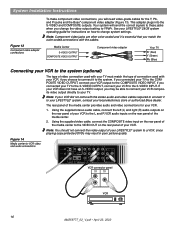
...L L L L L FM 75 ANTENNA 1 OPTICAL OPTICAL R R R R R VIDEO INPUTS COMPOSITE S-VIDEO 2 SPEAKER ZONES INPUT OUTPUT DIGITAL AUDIO OUTPUTS DIGITAL DIGITAL DIGITAL AUDIO INPUTS DIGITAL COMPOSITE S-VIDEO VIDEO OUTPUTS VCR connector panel AUDIO OUT VIDEO OUT R L VCR 16 AM259777_02_V.pdf • April 23, 2002 See your ... will need video-grade cables for instructions on the rear panel of the media center provides audio and video connections for your LIFESTYLE® 28/35 system operating guide for the Y, Pb, and Pr jacks and the Bose® component video adapter...
...L L L L L FM 75 ANTENNA 1 OPTICAL OPTICAL R R R R R VIDEO INPUTS COMPOSITE S-VIDEO 2 SPEAKER ZONES INPUT OUTPUT DIGITAL AUDIO OUTPUTS DIGITAL DIGITAL DIGITAL AUDIO INPUTS DIGITAL COMPOSITE S-VIDEO VIDEO OUTPUTS VCR connector panel AUDIO OUT VIDEO OUT R L VCR 16 AM259777_02_V.pdf • April 23, 2002 See your ... will need video-grade cables for instructions on the rear panel of the media center provides audio and video connections for your LIFESTYLE® 28/35 system operating guide for the Y, Pb, and Pr jacks and the Bose® component video adapter...
Installation guide
Page 17
... to connect it to your LIFESTYLE® system, contact your local electronics store or authorized Bose dealer. Note: If your cable/satellite box did not come with a temporary headset connection during the final installation steps. 2. The AUX jacks are required for your cable/satellite box to the L and R AUX audio inputs on the rear panel...
... to connect it to your LIFESTYLE® system, contact your local electronics store or authorized Bose dealer. Note: If your cable/satellite box did not come with a temporary headset connection during the final installation steps. 2. The AUX jacks are required for your cable/satellite box to the L and R AUX audio inputs on the rear panel...
Installation guide
Page 25
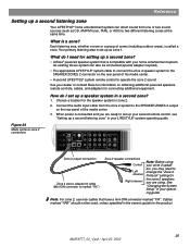
... on obtaining additional powered speakers, remote controls, cables, and adapters for setting up a second zone? • A Bose® powered speaker system that have a mini-DIN connector marked "FIX". Connect the audio input cable from one or two sound sources (such as zone 1. See "Changing the System Setup" in your LIFESTYLE® system operating guide. Your primary...
... on obtaining additional powered speakers, remote controls, cables, and adapters for setting up a second zone? • A Bose® powered speaker system that have a mini-DIN connector marked "FIX". Connect the audio input cable from one or two sound sources (such as zone 1. See "Changing the System Setup" in your LIFESTYLE® system operating guide. Your primary...


