Installation guide
Page 2
... user to loud music may be used without prior written permission. No part of important operating and maintenance instructions in the shipping carton. ©2010 Bose Corporation.
... user to loud music may be used without prior written permission. No part of important operating and maintenance instructions in the shipping carton. ©2010 Bose Corporation.

Installation guide
Page 3
iii X: Indicates that this toxic or hazardous substance contained in all of the homogeneous materials for this part is above the limit requirement in SJ/T 11363-2006. English TAB 2 TAB 3 TAB 4 TAB 5 TAB 6 TAB 7 TAB 8 Batteries Please dispose of used for this part is below the limit requirement in SJ/T 11363-2006. Names and Contents of Toxic or Hazardous Substances or Elements Toxic or Hazardous Substances and Elements Lead Mercury Cadmium Hexavalent Polybrominated Polybrominated Part Name (Pb) (Hg) (Cd) (CR(VI)) Biphenyl (PBB) diphenylether (PBDE) PCBs X 0 0...
iii X: Indicates that this toxic or hazardous substance contained in all of the homogeneous materials for this part is above the limit requirement in SJ/T 11363-2006. English TAB 2 TAB 3 TAB 4 TAB 5 TAB 6 TAB 7 TAB 8 Batteries Please dispose of used for this part is below the limit requirement in SJ/T 11363-2006. Names and Contents of Toxic or Hazardous Substances or Elements Toxic or Hazardous Substances and Elements Lead Mercury Cadmium Hexavalent Polybrominated Polybrominated Part Name (Pb) (Hg) (Cd) (CR(VI)) Biphenyl (PBB) diphenylether (PBDE) PCBs X 0 0...
Installation guide
Page 5
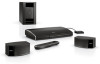
Unpacking The parts of the packing materials. These provide the safest means for choosing a Bose® LIFESTYLE® 235 home entertainment system. Interactive setup phase: Completing your setup following the interactive steps on your new system are two phases to the address...appears damaged, do not attempt to save all of your TV screen provided by the UnifyTM intelligent integration system. Be sure to use it. For Bose contact information, refer to the setup process: Physical setup phase: Placing the system components and connecting them together. There are packaged in Kit 4. ...
Unpacking The parts of the packing materials. These provide the safest means for choosing a Bose® LIFESTYLE® 235 home entertainment system. Interactive setup phase: Completing your setup following the interactive steps on your new system are two phases to the address...appears damaged, do not attempt to save all of your TV screen provided by the UnifyTM intelligent integration system. Be sure to use it. For Bose contact information, refer to the setup process: Physical setup phase: Placing the system components and connecting them together. There are packaged in Kit 4. ...
Installation guide
Page 6
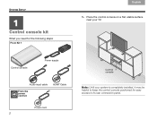
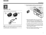
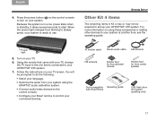
Place the control console on a flat, stable surface near your system is completely installed, it may be helpful to its rear connection panel. TAB 8 TAB 7 SYSTEM SETUP TAB 6 11 Control console kit What you need for easy access to keep the control console positioned for the following steps: From Kit 1 TAB 5 TAB 4 TAB 3 TAB 2 English 1. Control console Power supply Audio input cable From the power cord kit HDMI® Cable Power cord 2 Control console Note: Until your TV.
Place the control console on a flat, stable surface near your system is completely installed, it may be helpful to its rear connection panel. TAB 8 TAB 7 SYSTEM SETUP TAB 6 11 Control console kit What you need for easy access to keep the control console positioned for the following steps: From Kit 1 TAB 5 TAB 4 TAB 3 TAB 2 English 1. Control console Power supply Audio input cable From the power cord kit HDMI® Cable Power cord 2 Control console Note: Until your TV.
Installation guide
Page 7
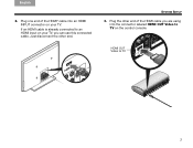
TAB 5 TAB 6 TAB 7 TAB 8 SYSTEM SETUP 3. Just disconnect the other end of the HDMI® cable into the connector labeled HDMI OUT Video to TV on your TV. English TAB 2 TAB 3 TAB 4 2. If an HDMI cable is already connected to TV 3 HDMI OUT Video to an HDMI input on your TV, you are using into an HDMI INPUT connector on the control console. Plug the other end. Plug one end of the HDMI cable you can use this connected cable.
TAB 5 TAB 6 TAB 7 TAB 8 SYSTEM SETUP 3. Just disconnect the other end of the HDMI® cable into the connector labeled HDMI OUT Video to TV on your TV. English TAB 2 TAB 3 TAB 4 2. If an HDMI cable is already connected to TV 3 HDMI OUT Video to an HDMI input on your TV, you are using into an HDMI INPUT connector on the control console. Plug the other end. Plug one end of the HDMI cable you can use this connected cable.

Installation guide
Page 8
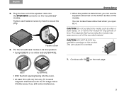
Plug the power supply output cord into the Acoustimass® Module connector on the plug faces up the next kit. Make sure you push the plug in as far as it while setting up . Continue with the arrow on the control console. Plug one end of the power cord into the power supply. Make sure the flat surface with Kit 2 on the floor. Remove a power cord from the power cord kit. 7. You will be asked to connect it can go. 8. Leave the other end of the power cord into a live AC (mains) power outlet. 9. Plug the other end of the audio input cable into the ...
Plug the power supply output cord into the Acoustimass® Module connector on the plug faces up the next kit. Make sure you push the plug in as far as it while setting up . Continue with the arrow on the control console. Plug one end of the power cord into the power supply. Make sure the flat surface with Kit 2 on the floor. Remove a power cord from the power cord kit. 7. You will be asked to connect it can go. 8. Leave the other end of the power cord into a live AC (mains) power outlet. 9. Plug the other end of the audio input cable into the ...

Installation guide
Page 9
Place the Acoustimass module on its side and locate the connector panel. Lay the module on the floor at the same end of the room as the TV. Acoustimass module Acoustimass module From the power cord kit Power cord 2. English TAB 2 TAB 3 TAB 4 2 Acoustimass® module kit What you need for the following steps: From Kit 2 TAB 5 TAB 6 TAB 7 TAB 8 SYSTEM SETUP 1. Make sure there is a live AC outlet nearby. Connector panel 5
Place the Acoustimass module on its side and locate the connector panel. Lay the module on the floor at the same end of the room as the TV. Acoustimass module Acoustimass module From the power cord kit Power cord 2. English TAB 2 TAB 3 TAB 4 2 Acoustimass® module kit What you need for the following steps: From Kit 2 TAB 5 TAB 6 TAB 7 TAB 8 SYSTEM SETUP 1. Make sure there is a live AC outlet nearby. Connector panel 5

Installation guide
Page 10
TAB 8 TAB 7 SYSTEM SETUP TAB 6 TAB 5 CAUTION: DO NOT stand the Acoustimass® module on the next page. 6 Media Center TAB 4 TAB 3 TAB 2 English 4. Remove a power cord from the control console, plug the free end into the Media Center connector on the Acoustimass module. Continue with the arrow faces the front of the module. Plug one end of the power cord into the AC Power connector on the Acoustimass module. Make sure you push the plug in as far as it can go. Plug the other end of the power cord into a live AC (mains) power outlet. 7. AC Power 6. Make sure the ...
TAB 8 TAB 7 SYSTEM SETUP TAB 6 TAB 5 CAUTION: DO NOT stand the Acoustimass® module on the next page. 6 Media Center TAB 4 TAB 3 TAB 2 English 4. Remove a power cord from the control console, plug the free end into the Media Center connector on the Acoustimass module. Continue with the arrow faces the front of the module. Plug one end of the power cord into the AC Power connector on the Acoustimass module. Make sure you push the plug in as far as it can go. Plug the other end of the power cord into a live AC (mains) power outlet. 7. AC Power 6. Make sure the ...
Installation guide
Page 11
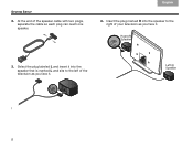
... of the TV and the other (marked R) to the left of the sound from the picture. Vary this distance to suit your local Bose dealer or visit www.Bose.com. Place the speaker marked L (on wall brackets or floor stands. Left (L) speaker Right (R) speaker • Keep each speaker facing straight out into...
... of the TV and the other (marked R) to the left of the sound from the picture. Vary this distance to suit your local Bose dealer or visit www.Bose.com. Place the speaker marked L (on wall brackets or floor stands. Left (L) speaker Right (R) speaker • Keep each speaker facing straight out into...
Installation guide
Page 12
Left (L) Speaker 8 TAB 4 TAB 3 TAB 2 English 4. At the end of the television as you face it . Insert the plug marked R into the speaker that is marked L and sits to the right of your television as you face it . Select the plug labeled L and insert it into the speaker to the left of the speaker cable with two plugs, separate the cable so each plug can reach one speaker. TAB 8 TAB 7 TAB 6 TAB 5 SYSTEM SETUP 2. Right (R) Speaker 3.
Left (L) Speaker 8 TAB 4 TAB 3 TAB 2 English 4. At the end of the television as you face it . Insert the plug marked R into the speaker that is marked L and sits to the right of your television as you face it . Select the plug labeled L and insert it into the speaker to the left of the speaker cable with two plugs, separate the cable so each plug can reach one speaker. TAB 8 TAB 7 TAB 6 TAB 5 SYSTEM SETUP 2. Right (R) Speaker 3.
Installation guide
Page 13
Fastener screw 6. This can locate these rubber feet when you open Kit 4. Tighten each fastener screw by hand to the module for long periods of the module. CAUTION: Do not put electronic media, such as video or audio tapes, on the bottom surface of time. English TAB 2 TAB 3 TAB 4 5. TAB 5 TAB 6 TAB 7 TAB 8 SYSTEM SETUP • When the position is determined, you still notice interference. 9 CAUTION: DO NOT BLOCK the ventilation openings on the next page. BEST ALTERNATE • With the front opening facing into the SPEAKERS connector on either side (...
Fastener screw 6. This can locate these rubber feet when you open Kit 4. Tighten each fastener screw by hand to the module for long periods of the module. CAUTION: Do not put electronic media, such as video or audio tapes, on the bottom surface of time. English TAB 2 TAB 3 TAB 4 5. TAB 5 TAB 6 TAB 7 TAB 8 SYSTEM SETUP • When the position is determined, you still notice interference. 9 CAUTION: DO NOT BLOCK the ventilation openings on the next page. BEST ALTERNATE • With the front opening facing into the SPEAKERS connector on either side (...

Installation guide
Page 14
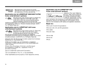
The instructions provided on your TV will tell you when to the markings inside the battery compartment. 3. You are in their final positions. • Do not connect any devices to the control console at this point you need for the following steps: From Kit 4 TAB 5 Remote control with batteries ADAPTiQ® audio calibration headset Congratulations! At this time. AA (IEC LR6) batteries (4) Battery compartment cover 2. Slide the battery cover back into place. 10 TAB 4 TAB 3 TAB 2 English IMPORTANT! • Before you start, make sure your speakers and Acoustimass ...
The instructions provided on your TV will tell you when to the markings inside the battery compartment. 3. You are in their final positions. • Do not connect any devices to the control console at this point you need for the following steps: From Kit 4 TAB 5 Remote control with batteries ADAPTiQ® audio calibration headset Congratulations! At this time. AA (IEC LR6) batteries (4) Battery compartment cover 2. Slide the battery cover back into place. 10 TAB 4 TAB 3 TAB 2 English IMPORTANT! • Before you start, make sure your speakers and Acoustimass ...
Installation guide
Page 15
...following: • Select your language. • Optimize the audio from blinking to steady green, your system is connected to control your LIFESTYLE® 235 system. When the power light changes from your system using these accessories or adding other devices to your system. IR emitter cable Stereo audio...the instructions on using the ADAPTiQ® audio calibration system. • Connect audio/video devices to the control console. • Configure your Bose® remote to your LIFESTYLE® 235 system. 7. English TAB 2 TAB 3 TAB 4 4. For more information on your TV. 6.
...following: • Select your language. • Optimize the audio from blinking to steady green, your system is connected to control your LIFESTYLE® 235 system. When the power light changes from your system using these accessories or adding other devices to your system. IR emitter cable Stereo audio...the instructions on using the ADAPTiQ® audio calibration system. • Connect audio/video devices to the control console. • Configure your Bose® remote to your LIFESTYLE® 235 system. 7. English TAB 2 TAB 3 TAB 4 4. For more information on your TV. 6.

Installation guide
Page 16
and other countries. ©2010 Bose Corporation. Rubber feet for greater stability and to protect your system setup. For help in your system operating guide. iPod and iPhone are placing the ... the module for Acoustimass module Bottom panel Vibration can reactivate the interactive setup mode at any problems, see the troubleshooting table in solving problems, contact Bose® Customer Service. No part of Apple Inc., registered in Kit 4. Contacting customer service For additional help in trying to resolve any time and correct...
and other countries. ©2010 Bose Corporation. Rubber feet for greater stability and to protect your system setup. For help in your system operating guide. iPod and iPhone are placing the ... the module for Acoustimass module Bottom panel Vibration can reactivate the interactive setup mode at any problems, see the troubleshooting table in solving problems, contact Bose® Customer Service. No part of Apple Inc., registered in Kit 4. Contacting customer service For additional help in trying to resolve any time and correct...

Installation guide
Page 18
©2010 Bose Corporation, The Mountain, Framingham, MA 01701-9168 USA AM328338 Rev.00
©2010 Bose Corporation, The Mountain, Framingham, MA 01701-9168 USA AM328338 Rev.00

Owner's guide
Page 2
... local building codes for the correct type of used in -wall installation. ii Please save all safety and operating instructions, including this guide carefully. All Bose® products must be used batteries properly, following any naked flame sources, such as the disconnect device, such disconnect device shall remain readily operable. •...
... local building codes for the correct type of used in -wall installation. ii Please save all safety and operating instructions, including this guide carefully. All Bose® products must be used batteries properly, following any naked flame sources, such as the disconnect device, such disconnect device shall remain readily operable. •...

Owner's guide
Page 3
... (on the connection panel of your Product Registration Card. English TAB 2 TAB 3 TAB 4 TAB 5 TAB 6 TAB 7 TAB 8 Bose Corporation hereby declares that this product is no guarantee that interference will not occur in a particular installation. These limits are located on the bottom... of the console, and on the carton): LIFESTYLE Serial numbers: Control console Acoustimass® module Retailer information: Dealer name Dealer phone Purchase date Please keep your sales receipt and ...
... (on the connection panel of your Product Registration Card. English TAB 2 TAB 3 TAB 4 TAB 5 TAB 6 TAB 7 TAB 8 Bose Corporation hereby declares that this product is no guarantee that interference will not occur in a particular installation. These limits are located on the bottom... of the console, and on the carton): LIFESTYLE Serial numbers: Control console Acoustimass® module Retailer information: Dealer name Dealer phone Purchase date Please keep your sales receipt and ...
Owner's guide
Page 4
...Microsoft Corporation. and other U.S. TiVo is a trademark of their respective owners. Other trademarks are trademarks of Dolby Laboratories. Applicable only for LIFESTYLE® 235 home entertainment systems "Made for iPod" and "Made for : iPod touch (1st and 2nd generation) iPod nano (3rd, 4th, ...DTS and the Symbol are registered trademarks & DTS Digital Surround and the DTS logos are trademarks of DTS, Inc. Applicable only for LIFESTYLE® 235 home entertainment systems Manufactured under license under U.S. Patent #'s: 5,956,674; 5,974,380 and 6,487,535 & other countries. DTS, ...
...Microsoft Corporation. and other U.S. TiVo is a trademark of their respective owners. Other trademarks are trademarks of Dolby Laboratories. Applicable only for LIFESTYLE® 235 home entertainment systems "Made for iPod" and "Made for : iPod touch (1st and 2nd generation) iPod nano (3rd, 4th, ...DTS and the Symbol are registered trademarks & DTS Digital Surround and the DTS logos are trademarks of DTS, Inc. Applicable only for LIFESTYLE® 235 home entertainment systems Manufactured under license under U.S. Patent #'s: 5,956,674; 5,974,380 and 6,487,535 & other countries. DTS, ...
Owner's guide
Page 6
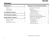
... a set-top box 8 Using the tuner in your TV 8 Tuning to a TV station 8 Playing audio/video devices 9 Listening to a Bose link input device 9 Playing an iPod or iPhone mobile digital device (on 235, V35, and V25 systems only 10 Using the front console inputs 11 Front USB input 11 Front Analog A/V input...
... a set-top box 8 Using the tuner in your TV 8 Tuning to a TV station 8 Playing audio/video devices 9 Listening to a Bose link input device 9 Playing an iPod or iPhone mobile digital device (on 235, V35, and V25 systems only 10 Using the front console inputs 11 Front USB input 11 Front Analog A/V input...
Owner's guide
Page 7
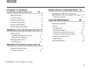
English TAB 2 TAB 3 TAB 4 TAB 5 TAB 6 TAB 7 TAB 8 LISTENING TO THE RADIO (ON 235, V25, AND V35 SYSTEMS ONLY) 13 Selecting the radio 13 Tuning to a station 13 Storing a preset station 13 Recalling a preset station 13 Deleting a preset station ... menu 16 REVIEWING YOUR SETUP SELECTIONS 18 Adjusting the system setup 18 Choices in the menu 18 ADDING SOUND TO ANOTHER ROOM 19 Expanding your 235, V35, or V25 system (Not available on T20, T10 systems, or in Japan.) . . 19 Expansion guidelines 19 CARE AND MAINTENANCE 20 Replacing the batteries 20...
English TAB 2 TAB 3 TAB 4 TAB 5 TAB 6 TAB 7 TAB 8 LISTENING TO THE RADIO (ON 235, V25, AND V35 SYSTEMS ONLY) 13 Selecting the radio 13 Tuning to a station 13 Storing a preset station 13 Recalling a preset station 13 Deleting a preset station ... menu 16 REVIEWING YOUR SETUP SELECTIONS 18 Adjusting the system setup 18 Choices in the menu 18 ADDING SOUND TO ANOTHER ROOM 19 Expanding your 235, V35, or V25 system (Not available on T20, T10 systems, or in Japan.) . . 19 Expansion guidelines 19 CARE AND MAINTENANCE 20 Replacing the batteries 20...
