The Bose® Lifestyle® amplifier - Owner's guide
Page 16
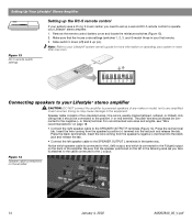
...Lifestyle® stereo amplifier. 1. Doing so may cause damage to the SPEAKER OUTPUT R terminals (Figure 14). Insert the wire coming from the speaker's positive (+) terminal into the black... jack and release the tab. • Connect the left speaker cable to the SPEAKER OUTPUT L terminals in more information on operating your first remote. 3. Slide switch 5 down (off) and 6 up a second RC-5 remote control to operate your Lifestyle...Up Your Lifestyle® ...connected to your Lifestyle® system...pdf Press the black terminal tab. .... or black) terminal. Make sure...
...Lifestyle® stereo amplifier. 1. Doing so may cause damage to the SPEAKER OUTPUT R terminals (Figure 14). Insert the wire coming from the speaker's positive (+) terminal into the black... jack and release the tab. • Connect the left speaker cable to the SPEAKER OUTPUT L terminals in more information on operating your first remote. 3. Slide switch 5 down (off) and 6 up a second RC-5 remote control to operate your Lifestyle...Up Your Lifestyle® ...connected to your Lifestyle® system...pdf Press the black terminal tab. .... or black) terminal. Make sure...
The Bose® Lifestyle® amplifier - Owner's guide
Page 20
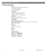
....7 cm x 7.8 cm) Weight 6 lb (2.72 kg) Finish Black powder coat Wire recommendations Gauge 18 (0.75 mm2) 16 (1.7 mm2) 14 (2.0 mm2) Length (max.) 30 ft (9 m) 45 ft (14 m) 70 ft (21 m) 18 January 4, 2002 AM262840_00_V.pdf W x 51/2 in . Maintaining Your Lifestyle® Stereo Amplifier Technical information Features • Bose® proprietary digital signal processing technology •...
....7 cm x 7.8 cm) Weight 6 lb (2.72 kg) Finish Black powder coat Wire recommendations Gauge 18 (0.75 mm2) 16 (1.7 mm2) 14 (2.0 mm2) Length (max.) 30 ft (9 m) 45 ft (14 m) 70 ft (21 m) 18 January 4, 2002 AM262840_00_V.pdf W x 51/2 in . Maintaining Your Lifestyle® Stereo Amplifier Technical information Features • Bose® proprietary digital signal processing technology •...

Owner's guide
Page 6
... and Color television system. A standard for National Television System Committee. IR - A video format which has black borders at the top and bottom of encoding multi-channel audio. - MPEG-1 Layer III audio. An acronym for storing and reproducing audio and video on ...
... and Color television system. A standard for National Television System Committee. IR - A video format which has black borders at the top and bottom of encoding multi-channel audio. - MPEG-1 Layer III audio. An acronym for storing and reproducing audio and video on ...

Owner's guide
Page 34
... DVD Setup Optical Source Optical Input Record Out Format TV Power Remote Control Setup Send IR Commands Receive IR Commands Tuner Spacing Video Format Video Black Level Video Output Zone 1 Protocol Zone 2 Protocol DVD Setup Auto Select Audio Track Auto Subtitle Enter DVD Autoplay Aspect Ratio Image Format Parental Control Setup...
... DVD Setup Optical Source Optical Input Record Out Format TV Power Remote Control Setup Send IR Commands Receive IR Commands Tuner Spacing Video Format Video Black Level Video Output Zone 1 Protocol Zone 2 Protocol DVD Setup Auto Select Audio Track Auto Subtitle Enter DVD Autoplay Aspect Ratio Image Format Parental Control Setup...

Owner's guide
Page 35
... Display Language: Optical Source: Optical Input: Record Out Format: TV Power: Send IR Commands: Receive IR Commands: Tuner Spacing: Video Format: Video Black Level: Video Output: Zone 1 Protocol: Zone 2 Protocol: Settings What each setting does 1 to 7 Determines the brightness level of the four sources... is selected (TV on some TVs. This setting may be useful to teach LIFESTYLE® remote commands to one of the media center display (7 = brightest). European Sets channel spacing for Bose® powered speaker systems, such as universal remotes, are received by your system...
... Display Language: Optical Source: Optical Input: Record Out Format: TV Power: Send IR Commands: Receive IR Commands: Tuner Spacing: Video Format: Video Black Level: Video Output: Zone 1 Protocol: Zone 2 Protocol: Settings What each setting does 1 to 7 Determines the brightness level of the four sources... is selected (TV on some TVs. This setting may be useful to teach LIFESTYLE® remote commands to one of the media center display (7 = brightest). European Sets channel spacing for Bose® powered speaker systems, such as universal remotes, are received by your system...

Installation guide
Page 10
... the Acoustimass module, and any additional equipment are joined together for easy cable connections. If you allow for your convenience, providing an easy-to the Bose address list included with your system. • Place the media center within 30 feet (9.1 m) of the Acoustimass® module (the length of the... pull apart the cables as it slides open the CD tray of the audio input cable). These wires match the positive (red) and negative (black) terminals on the bottom of the media center. • Place the media center close enough to other sound sources (TV and VCR) to its...
... the Acoustimass module, and any additional equipment are joined together for easy cable connections. If you allow for your convenience, providing an easy-to the Bose address list included with your system. • Place the media center within 30 feet (9.1 m) of the Acoustimass® module (the length of the... pull apart the cables as it slides open the CD tray of the audio input cable). These wires match the positive (red) and negative (black) terminals on the bottom of the media center. • Place the media center close enough to other sound sources (TV and VCR) to its...

Installation guide
Page 11
... of the five speakers. 3. Connect each of the speaker and insert the marked wire (+) into the red terminal and the plain wire (-) into the black terminal. Plug the orange connectors into the matching left surround and right surround jacks. Press the terminal tab on the Acoustimass® module (Figure 8). Release...
... of the five speakers. 3. Connect each of the speaker and insert the marked wire (+) into the red terminal and the plain wire (-) into the black terminal. Plug the orange connectors into the matching left surround and right surround jacks. Press the terminal tab on the Acoustimass® module (Figure 8). Release...

Installation guide
Page 12
... at side facing up a second listening zone" on page 23 for information on the connector. 12 Note: Be sure that each jack. 1. Plug the small black multi-pin connector (flat the Acoustimass module. CAUTION: Do not place strain on the audio input cable, especially on the cable may cause damage...
... at side facing up a second listening zone" on page 23 for information on the connector. 12 Note: Be sure that each jack. 1. Plug the small black multi-pin connector (flat the Acoustimass module. CAUTION: Do not place strain on the audio input cable, especially on the cable may cause damage...

Installation guide
Page 24
... L (left) channel. A Y adapter can be used to connect mono sources. Be sure to match the red connector to the R (right) channel and the white (or black) connector to your system using standard RCA audio cables.
... L (left) channel. A Y adapter can be used to connect mono sources. Be sure to match the red connector to the R (right) channel and the white (or black) connector to your system using standard RCA audio cables.
