
Owner's guide
Page 4
... structure, grounding of antenna-discharge unit, connection to CATV system installer This reminder is grounded. Antenna lead in wire to an antenna discharge unit, size of grounding conductors, location of the lead-in wire Ground clamp Electric service equipment Antenna discharge unit (NEC Section 810-20) Grounding conductors (NEC Section 810-21...
... structure, grounding of antenna-discharge unit, connection to CATV system installer This reminder is grounded. Antenna lead in wire to an antenna discharge unit, size of grounding conductors, location of the lead-in wire Ground clamp Electric service equipment Antenna discharge unit (NEC Section 810-20) Grounding conductors (NEC Section 810-21...

Owner's guide
Page 9
... Center, Right, and Left front cube arrays. Connect the Powered Acoustimass module to the center and front cube arrays Three individual 20 (6m) foot wire pairs connect the Powered Acoustimass module to a receiver output. Connect the wire pair marked C to the receiver. Figure 4 Separating cables Figure ... terminal. Each cable connects to the left front speaker. Connect the wire pair marked L to the module with a single plug. 1. Setting Up Connect the speakers Connect the cube arrays to the Powered Acoustimass® module, and then connect the module to your system. Check...
... Center, Right, and Left front cube arrays. Connect the Powered Acoustimass module to the center and front cube arrays Three individual 20 (6m) foot wire pairs connect the Powered Acoustimass module to a receiver output. Connect the wire pair marked C to the receiver. Figure 4 Separating cables Figure ... terminal. Each cable connects to the left front speaker. Connect the wire pair marked L to the module with a single plug. 1. Setting Up Connect the speakers Connect the cube arrays to the Powered Acoustimass® module, and then connect the module to your system. Check...
Owner's guide
Page 10
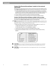
... of cube array to insert the marked wire into the red terminal and the plain wire into their jacks at the Powered Acoustimass module. If your receiver. 8 October 22, 2001 AM194452_06_V.pdf Setting Up Connect the Powered Acoustimass® module to the surround cube arrays The 50 foot (15 m) cable with a cover installed. Each has...
... of cube array to insert the marked wire into the red terminal and the plain wire into their jacks at the Powered Acoustimass module. If your receiver. 8 October 22, 2001 AM194452_06_V.pdf Setting Up Connect the Powered Acoustimass® module to the surround cube arrays The 50 foot (15 m) cable with a cover installed. Each has...
Owner's guide
Page 11
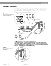
...SURROUND SPEAKERS R REAR L CENTER LFE/SUBWOOFER OUT Figure 7 Turn on the Powered Acoustimass module Plug in the Powered Acoustimass Module When you plug your room. The speaker system turns on (Figure 7). Incorrect wiring can result in the power cord of module output. Check that all connections from the... receiver to the Powered Acoustimass module and from the receiver. Be sure to turn the module off after each use. Correct wiring problems before you have checked all cube arrays are connected in phase (+ ...
...SURROUND SPEAKERS R REAR L CENTER LFE/SUBWOOFER OUT Figure 7 Turn on the Powered Acoustimass module Plug in the Powered Acoustimass Module When you plug your room. The speaker system turns on (Figure 7). Incorrect wiring can result in the power cord of module output. Check that all connections from the... receiver to the Powered Acoustimass module and from the receiver. Be sure to turn the module off after each use. Correct wiring problems before you have checked all cube arrays are connected in phase (+ ...

Owner's guide
Page 14
... surround-sound • Make sure the receiver and Powered Acoustimass module are plugged into any headphones. • Increase the volume. • Be sure the Powered Acoustimass module is plugged in solving problems, contact Bose customer service. Also, do System does not function at ..., 2001 AM194452_06_V.pdf For example: select DVD audio on . • Make sure speaker wire is correct. If you still have a problem with your Acoustimass 15 speakers, turn off your Acoustimass 15 speaker system may be sure a coaxial or optical cable connects the digital output of the DVD...
... surround-sound • Make sure the receiver and Powered Acoustimass module are plugged into any headphones. • Increase the volume. • Be sure the Powered Acoustimass module is plugged in solving problems, contact Bose customer service. Also, do System does not function at ..., 2001 AM194452_06_V.pdf For example: select DVD audio on . • Make sure speaker wire is correct. If you still have a problem with your Acoustimass 15 speakers, turn off your Acoustimass 15 speaker system may be sure a coaxial or optical cable connects the digital output of the DVD...
Owner's guide
Page 15
... speaker arrays: 6.2"H x 3.1"W x 4.0"D (15.7 cm x 7.8 cm x 10.2 cm) 2.4 lb (1.1 kg) Powered Acoustimass module: 14.0"H x 23.3"W x 7.5"D (35.5 cm x 19.0 cm x 59.0 cm) 33 lb (15 kg) Packed system: 53 lb (24 kg) Warranty period Bose® Acoustimass 15 speakers are covered by a limited five-year ...transferable warranty. Accessories Floor stands: UFS-20B (black), UFS-20W (white) Wall brackets: UB-20B (black), UB-20W (white) Module input cable adapter for use with existing wiring: PN194460-001 (...
... speaker arrays: 6.2"H x 3.1"W x 4.0"D (15.7 cm x 7.8 cm x 10.2 cm) 2.4 lb (1.1 kg) Powered Acoustimass module: 14.0"H x 23.3"W x 7.5"D (35.5 cm x 19.0 cm x 59.0 cm) 33 lb (15 kg) Packed system: 53 lb (24 kg) Warranty period Bose® Acoustimass 15 speakers are covered by a limited five-year ...transferable warranty. Accessories Floor stands: UFS-20B (black), UFS-20W (white) Wall brackets: UB-20B (black), UB-20W (white) Module input cable adapter for use with existing wiring: PN194460-001 (...


