
Owner's guide
Page 4
...all outdoor antennas - Refer to keep from touching power lines or circuits, as per National Electrical Code, ANSI/NFPA 70. Antenna lead in wire to an antenna discharge unit, size of grounding conductors, location of the National Electrical Code ANSI/ NFPA No. 70 provides information with them may...) that the cable ground shall be connected to the grounding system of the building, as close to the point of the lead-in wire Ground clamp Electric service equipment Antenna discharge unit (NEC Section 810-20) Grounding conductors (NEC Section 810-21) Ground clamps Power service grounding...
...all outdoor antennas - Refer to keep from touching power lines or circuits, as per National Electrical Code, ANSI/NFPA 70. Antenna lead in wire to an antenna discharge unit, size of grounding conductors, location of the National Electrical Code ANSI/ NFPA No. 70 provides information with them may...) that the cable ground shall be connected to the grounding system of the building, as close to the point of the lead-in wire Ground clamp Electric service equipment Antenna discharge unit (NEC Section 810-20) Grounding conductors (NEC Section 810-21) Ground clamps Power service grounding...

Owner's guide
Page 9
... press the terminal tab on the back of the TV as needed to comfortably reach the speakers. Connect the wire pair marked C to the receiver. Always connect the cube arrays to the Powered Acoustimass module, then connect the module to the center speaker. CAUTION: Never use broken or frayed... wiring, which can result in -wall installation. Release the tab to secure the wires. 2. Setting Up Connect the speakers Connect the cube arrays to the Powered Acoustimass® module, and then connect the module to your receiver and...
... press the terminal tab on the back of the TV as needed to comfortably reach the speakers. Connect the wire pair marked C to the receiver. Always connect the cube arrays to the Powered Acoustimass module, then connect the module to the center speaker. CAUTION: Never use broken or frayed... wiring, which can result in -wall installation. Release the tab to secure the wires. 2. Setting Up Connect the speakers Connect the cube arrays to the Powered Acoustimass® module, and then connect the module to your receiver and...
Owner's guide
Page 10
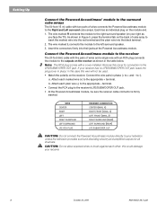
... terminal tab on the back of cube array to insert the marked wire into the red terminal and the plain wire into their jacks at the Powered Acoustimass module. Insert the connectors firmly into the black terminal. 2. WIRE CENTER RIGHT LEFT RIGHT SURROUND LEFT SURROUND LFE RCA PLUG RECEIVER CONNECTION ...(on your receiver. 8 October 22, 2001 AM194452_06_V.pdf Setting Up Connect the Powered Acoustimass® module to the surround cube arrays The 50 foot (15 m) cable with two pairs of wires and a single wire with an RCA plug connects the module to the outputs on the receiver as you ...
... terminal tab on the back of cube array to insert the marked wire into the red terminal and the plain wire into their jacks at the Powered Acoustimass module. Insert the connectors firmly into the black terminal. 2. WIRE CENTER RIGHT LEFT RIGHT SURROUND LEFT SURROUND LFE RCA PLUG RECEIVER CONNECTION ...(on your receiver. 8 October 22, 2001 AM194452_06_V.pdf Setting Up Connect the Powered Acoustimass® module to the surround cube arrays The 50 foot (15 m) cable with two pairs of wires and a single wire with an RCA plug connects the module to the outputs on the receiver as you ...
Owner's guide
Page 11
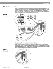
... result in phase (+ to the cube arrays (Figure 6). AM194452_06_V.pdf October 22, 2001 9 Correct wiring problems before you have checked all connections, plug in the Powered Acoustimass Module When you plug your room. It is not necessary to turn the module off at the receiver. The ... Up Check the connections Check all connections from the receiver to the Powered Acoustimass module and from the receiver. Be sure to turn it receives a signal from the module to + and - Make sure all wires are connected to the proper terminals according to -). to their position in ...
... result in phase (+ to the cube arrays (Figure 6). AM194452_06_V.pdf October 22, 2001 9 Correct wiring problems before you have checked all connections, plug in the Powered Acoustimass Module When you plug your room. It is not necessary to turn the module off at the receiver. The ... Up Check the connections Check all connections from the receiver to the Powered Acoustimass module and from the receiver. Be sure to turn it receives a signal from the module to + and - Make sure all wires are connected to the proper terminals according to -). to their position in ...

Owner's guide
Page 14
...any solvents, chemicals, or cleaning solutions containing alcohol, ammonia, or abrasives. The grille assemblies on . • Make sure speaker wire is Dolby Digital encoded. Move it farther away from cube arrays Sound is correct. See the inside back cover of external components ... Increase the volume. • Be sure the Powered Acoustimass module is plugged in solving problems, contact Bose customer service. Customer service For additional help in and turned on the cube arrays may be cleaned with your Acoustimass 15 speakers, turn off your receiver is processing a signal ...
...any solvents, chemicals, or cleaning solutions containing alcohol, ammonia, or abrasives. The grille assemblies on . • Make sure speaker wire is Dolby Digital encoded. Move it farther away from cube arrays Sound is correct. See the inside back cover of external components ... Increase the volume. • Be sure the Powered Acoustimass module is plugged in solving problems, contact Bose customer service. Customer service For additional help in and turned on the cube arrays may be cleaned with your Acoustimass 15 speakers, turn off your receiver is processing a signal ...
Owner's guide
Page 15
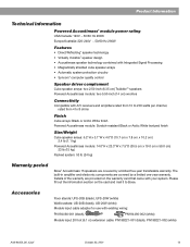
... control Speaker driver complement Cube speaker arrays: two 2.50-inch (6.35 cm) TwiddlerTM speakers Powered Acoustimass module: two 5.50-inch (14 cm) woofers Connectivity Compatible with existing wiring: PN194460-001 (black), PN194460-002 (white) Module input 20 foot (6.1 m) extension cable: ...speaker arrays: 6.2"H x 3.1"W x 4.0"D (15.7 cm x 7.8 cm x 10.2 cm) 2.4 lb (1.1 kg) Powered Acoustimass module: 14.0"H x 23.3"W x 7.5"D (35.5 cm x 19.0 cm x 59.0 cm) 33 lb (15 kg) Packed system: 53 lb (24 kg) Warranty period Bose® Acoustimass 15 speakers are covered by a limited five-year ...
... control Speaker driver complement Cube speaker arrays: two 2.50-inch (6.35 cm) TwiddlerTM speakers Powered Acoustimass module: two 5.50-inch (14 cm) woofers Connectivity Compatible with existing wiring: PN194460-001 (black), PN194460-002 (white) Module input 20 foot (6.1 m) extension cable: ...speaker arrays: 6.2"H x 3.1"W x 4.0"D (15.7 cm x 7.8 cm x 10.2 cm) 2.4 lb (1.1 kg) Powered Acoustimass module: 14.0"H x 23.3"W x 7.5"D (35.5 cm x 19.0 cm x 59.0 cm) 33 lb (15 kg) Packed system: 53 lb (24 kg) Warranty period Bose® Acoustimass 15 speakers are covered by a limited five-year ...


