Installation Instructions
Page 3
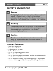
..., stoves, or other equipment (including amplifiers) that may be of sufficient magnitude to constitute a risk to qualified service personnel. Bosch Security Systems | 2005-11 | V1.0 Caution To reduce the risk of important operating and maintenance (servicing) instructions in accordance with... 7. Refer servicing to persons. Clean only with all instructions. 5. Install in the literature accompanying the appliance. FlexiDomeVF | User Manual EN | 3 SAFETY PRECAUTIONS Danger The lightning flash with arrowhead symbol, within the product's enclosure that produce heat. Warning The ...
..., stoves, or other equipment (including amplifiers) that may be of sufficient magnitude to constitute a risk to qualified service personnel. Bosch Security Systems | 2005-11 | V1.0 Caution To reduce the risk of important operating and maintenance (servicing) instructions in accordance with... 7. Refer servicing to persons. Clean only with all instructions. 5. Install in the literature accompanying the appliance. FlexiDomeVF | User Manual EN | 3 SAFETY PRECAUTIONS Danger The lightning flash with arrowhead symbol, within the product's enclosure that produce heat. Warning The ...
Installation Instructions
Page 4
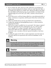
...with a contact separation of the building. An all servicing to qualified service personnel. The power supply must comply with one wider than the other. Bosch Security Systems | 2005-11 | V1.0 Do not defeat the safety purpose of fire or electric shock, this equipment during lightning storms or when... or moisture, does not operate normally, or has been dropped. 14. Warning To reduce the risk of the polarized or grounding-type plug. FlexiDomeVF | User Manual EN | 4 9. Refer all -pole mains switch with liquids, such as vases, should not be a SELV-LPS unit or a SELV Class 2 unit (...
...with a contact separation of the building. An all servicing to qualified service personnel. The power supply must comply with one wider than the other. Bosch Security Systems | 2005-11 | V1.0 Do not defeat the safety purpose of fire or electric shock, this equipment during lightning storms or when... or moisture, does not operate normally, or has been dropped. 14. Warning To reduce the risk of the polarized or grounding-type plug. FlexiDomeVF | User Manual EN | 4 9. Refer all -pole mains switch with liquids, such as vases, should not be a SELV-LPS unit or a SELV Class 2 unit (...
Installation Instructions
Page 5
... determined by turning the equipment off and on a circuit different from that interference will not occur in a residential installation. FlexiDomeVF | User Manual EN | 5 FCC Information This equipment has been tested and found to comply with the instructions, may cause harmful interference to radio communications....into an outlet on , the user is encouraged to try to correct the interference by Bosch could void the user's authority to you or visit our web site at www.boschsecuritysystems.com Bosch Security Systems | 2005-11 | V1.0 For additional information or to speak to a ...
... determined by turning the equipment off and on a circuit different from that interference will not occur in a residential installation. FlexiDomeVF | User Manual EN | 5 FCC Information This equipment has been tested and found to comply with the instructions, may cause harmful interference to radio communications....into an outlet on , the user is encouraged to try to correct the interference by Bosch could void the user's authority to you or visit our web site at www.boschsecuritysystems.com Bosch Security Systems | 2005-11 | V1.0 For additional information or to speak to a ...
Installation Instructions
Page 6
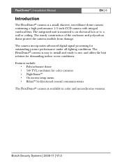
FlexiDomeVF | Installation Manual EN | 6 Introduction The FlexiDomeVF camera is mounted to an electrical box or to use, and offers the best solution for demanding indoor scene conditions. The ...; • On-screen setup menu • Bilinx™ bi-directional coaxial communications The FlexiDomeVF camera is easy to install and ready to a wall or ceiling. Bosch Security Systems | 2005-11 | V1.0 The FlexiDomeVF camera is available in color and monochrome versions. The integrated unit is a small, discreet, surveillance dome camera containing...
FlexiDomeVF | Installation Manual EN | 6 Introduction The FlexiDomeVF camera is mounted to an electrical box or to use, and offers the best solution for demanding indoor scene conditions. The ...; • On-screen setup menu • Bilinx™ bi-directional coaxial communications The FlexiDomeVF camera is easy to install and ready to a wall or ceiling. Bosch Security Systems | 2005-11 | V1.0 The FlexiDomeVF camera is available in color and monochrome versions. The integrated unit is a small, discreet, surveillance dome camera containing...
Installation Instructions
Page 7
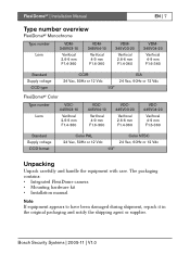
... shipment, repack it in the original packaging and notify the shipping agent or supplier. Bosch Security Systems | 2005-11 | V1.0 FlexiDomeVF | Installation Manual EN | 7 Type number overview FlexiDomeVF Monochrome Type number Lens VDM345V03-10 Varifocal 2.6-6... mm F1.4-360 VDM345V04-10 Varifocal 4-9 mm F1.6-360 VDM345V03-20 Varifocal 2.6-6 mm F1.4-360 VDM345V04-20 Varifocal 4-9 mm F1.6-360 Standard Supply voltage CCD type CCIR EIA 24 Vac, 50Hz or 12 Vdc 24 Vac, 60Hz or 12 Vdc...
... shipment, repack it in the original packaging and notify the shipping agent or supplier. Bosch Security Systems | 2005-11 | V1.0 FlexiDomeVF | Installation Manual EN | 7 Type number overview FlexiDomeVF Monochrome Type number Lens VDM345V03-10 Varifocal 2.6-6... mm F1.4-360 VDM345V04-10 Varifocal 4-9 mm F1.6-360 VDM345V03-20 Varifocal 2.6-6 mm F1.4-360 VDM345V04-20 Varifocal 4-9 mm F1.6-360 Standard Supply voltage CCD type CCIR EIA 24 Vac, 50Hz or 12 Vdc 24 Vac, 60Hz or 12 Vdc...
Installation Instructions
Page 8
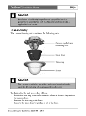
Bosch Security Systems | 2005-11 | V1.0 To disasemble the unit proceed as follows: • Rotate the trim ring counterclockwise to release it off of the following ... pulling it from its bayonet on the camera base. • Remove the trim ring with the National Electrical Code or applicable local codes. FlexiDomeVF | Installation Manual EN | 8 Caution Installation should only be handled carefully. Disassembly The camera/housing unit consists of the base. Do not drop when disassembling the unit.
Bosch Security Systems | 2005-11 | V1.0 To disasemble the unit proceed as follows: • Rotate the trim ring counterclockwise to release it off of the following ... pulling it from its bayonet on the camera base. • Remove the trim ring with the National Electrical Code or applicable local codes. FlexiDomeVF | Installation Manual EN | 8 Caution Installation should only be handled carefully. Disassembly The camera/housing unit consists of the base. Do not drop when disassembling the unit.
Installation Instructions
Page 9
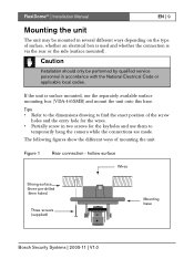
... onto this base. Figure 1 Rear connection - hollow surface Wires Strong surface (three pre-drilled 8mm holes) Three screws (supplied) Mounting base Bosch Security Systems | 2005-11 | V1.0 Tips • Refer to the dimensions drawing to temporarily hang the camera while the connections are made.... Caution Installation should only be mounted in several different ways depending on the type of mounting the unit. FlexiDomeVF | Installation Manual EN | 9 Mounting the unit The unit may be performed by qualified service personnel in two screws for the wires. • ...
... onto this base. Figure 1 Rear connection - hollow surface Wires Strong surface (three pre-drilled 8mm holes) Three screws (supplied) Mounting base Bosch Security Systems | 2005-11 | V1.0 Tips • Refer to the dimensions drawing to temporarily hang the camera while the connections are made.... Caution Installation should only be mounted in several different ways depending on the type of mounting the unit. FlexiDomeVF | Installation Manual EN | 9 Mounting the unit The unit may be performed by qualified service personnel in two screws for the wires. • ...
Installation Instructions
Page 10
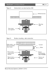
side connection Solid surface (three pre-drilled 8mm holes) Three screws (supplied with camera) Three screws (M5, supplied) Conduit Wires Raised mounting base (VDA-445SMB) Camera unit and base Bosch Security Systems | 2005-11 | V1.0 FlexiDomeVF | Installation Manual Figure 2 Connection to an electrical box (4S) EN | 10 S4 Electrical box Two screws (not supplied) Mounting base Figure 3 Surface mounting -
side connection Solid surface (three pre-drilled 8mm holes) Three screws (supplied with camera) Three screws (M5, supplied) Conduit Wires Raised mounting base (VDA-445SMB) Camera unit and base Bosch Security Systems | 2005-11 | V1.0 FlexiDomeVF | Installation Manual Figure 2 Connection to an electrical box (4S) EN | 10 S4 Electrical box Two screws (not supplied) Mounting base Figure 3 Surface mounting -
Installation Instructions
Page 11
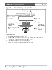
... a rear connection, leave the cap in place. • Attach the conduit to the mounting base. • Make the connection inside the mounting case. FlexiDomeVF | Installation Manual Figure 4 Surface mounting - Bosch Security Systems | 2005-11 | V1.0
... a rear connection, leave the cap in place. • Attach the conduit to the mounting base. • Make the connection inside the mounting case. FlexiDomeVF | Installation Manual Figure 4 Surface mounting - Bosch Security Systems | 2005-11 | V1.0
Installation Instructions
Page 12
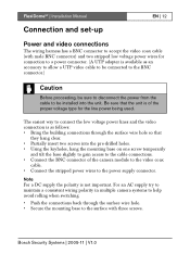
Bosch Security Systems | 2005-11 | V1.0 The easiest way to connect the low voltage power lines and the video connection is available as follows: • Bring ... the BNC connector of the camera module to the video coax cable. • Connect the stripped power wires to the power supply connector. FlexiDomeVF | Installation Manual Connection and set-up EN | 12 Power and video connections The wiring harness has a BNC connector to accept the video coax cable (with three screws.
Bosch Security Systems | 2005-11 | V1.0 The easiest way to connect the low voltage power lines and the video connection is available as follows: • Bring ... the BNC connector of the camera module to the video coax cable. • Connect the stripped power wires to the power supply connector. FlexiDomeVF | Installation Manual Connection and set-up EN | 12 Power and video connections The wiring harness has a BNC connector to accept the video coax cable (with three screws.
Installation Instructions
Page 13
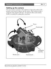
Focus Focal length Monitor jack Thumbwheels Navigation switches Bosch Security Systems | 2005-11 | V1.0 FlexiDomeVF | Installation Manual EN | 13 Setting up the camera You can connect a monitor to the miniature 2.5mm jack socket on the printed circuit board to help set up the camera. This socket provides a composite video signal (with sync). An optional cable (code number S1460) is available for making this connection.
Focus Focal length Monitor jack Thumbwheels Navigation switches Bosch Security Systems | 2005-11 | V1.0 FlexiDomeVF | Installation Manual EN | 13 Setting up the camera You can connect a monitor to the miniature 2.5mm jack socket on the printed circuit board to help set up the camera. This socket provides a composite video signal (with sync). An optional cable (code number S1460) is available for making this connection.

Installation Instructions
Page 14
... horizontal adjustment (pan), rotate the camera module in the base. The camera module position can be adjusted along three axes. Refocus if necessary. FlexiDomeVF | Installation Manual EN | 14 Camera positioning The physical default position of the camera is held in place. When adjusting the camera position ensure that the top of... the varifocal lens, loosen the focal length screw and turn the mechanism until the desired view is level. Do not rotate more than 340°. Bosch Security Systems | 2005-11 | V1.0
... horizontal adjustment (pan), rotate the camera module in the base. The camera module position can be adjusted along three axes. Refocus if necessary. FlexiDomeVF | Installation Manual EN | 14 Camera positioning The physical default position of the camera is held in place. When adjusting the camera position ensure that the top of... the varifocal lens, loosen the focal length screw and turn the mechanism until the desired view is level. Do not rotate more than 340°. Bosch Security Systems | 2005-11 | V1.0
Installation Instructions
Page 15
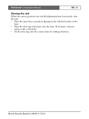
FlexiDomeVF | Installation Manual EN | 15 Closing the unit When the camera position is set and all adjustments have been made, close the unit. • Place the inner liner in position aligning its fin with the bracket on the base. • Place the trim ring with dome onto the base. (If necessary clean its surface with a soft cloth.) • Fix the trim ring onto the camera base by rotating clockwise. Bosch Security Systems | 2005-11 | V1.0
FlexiDomeVF | Installation Manual EN | 15 Closing the unit When the camera position is set and all adjustments have been made, close the unit. • Place the inner liner in position aligning its fin with the bracket on the base. • Place the trim ring with dome onto the base. (If necessary clean its surface with a soft cloth.) • Fix the trim ring onto the camera base by rotating clockwise. Bosch Security Systems | 2005-11 | V1.0
Installation Instructions
Page 16
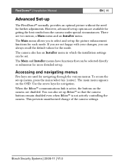
... menu appears on the camera are not happy with your changes, you to select and set -up options are available for more detailed set-up. Bosch Security Systems | 2005-11 | V1.0 FlexiDomeVF | Installation Manual EN | 16 Advanced Set-up The FlexiDomeVF normally provides an optimal picture without the need for navigation.
... menu appears on the camera are not happy with your changes, you to select and set -up options are available for more detailed set-up. Bosch Security Systems | 2005-11 | V1.0 FlexiDomeVF | Installation Manual EN | 16 Advanced Set-up The FlexiDomeVF normally provides an optimal picture without the need for navigation.
Installation Instructions
Page 17
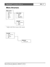
FlexiDomeVF | Installation Manual Menu Structure Main menu Level Shut/AGC BLC Color Sync Vphase Exit Shut/AGC Shutter AGC Auto black NightSense* COLOR* White balance R-gain B-gain * Only for the Color version of the camera. EN | 17 Bosch Security Systems | 2005-11 | V1.0 Installer Set focus now Comm Defaults Exit Defaults Restore all?
FlexiDomeVF | Installation Manual Menu Structure Main menu Level Shut/AGC BLC Color Sync Vphase Exit Shut/AGC Shutter AGC Auto black NightSense* COLOR* White balance R-gain B-gain * Only for the Color version of the camera. EN | 17 Bosch Security Systems | 2005-11 | V1.0 Installer Set focus now Comm Defaults Exit Defaults Restore all?
Installation Instructions
Page 18
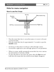
Bosch Security Systems | 2005-11 | V1.0 FlexiDomeVF | Installation Manual Hints for menu navigation How to use the 5 keys Camera base Up key Left key EN | 18 Menu/select key Right key Down key • ...
Bosch Security Systems | 2005-11 | V1.0 FlexiDomeVF | Installation Manual Hints for menu navigation How to use the 5 keys Camera base Up key Left key EN | 18 Menu/select key Right key Down key • ...
Installation Instructions
Page 19
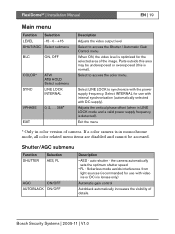
...is normal). flickerless mode avoids interference from light sources (recommended for use with internal synchronization (automatically selected with the power supply frequency. Bosch Security Systems | 2005-11 | V1.0 Select LINE LOCK to access the color menu. the camera automatically sets the optimum shutter ... FL - Shutter/AGC submenu Function SHUTTER Selection AES, FL AGC ON/OFF AUTOBLACK ON/OFF Description • AES - FlexiDomeVF | Installation Manual EN | 19 Main menu Function Selection LEVEL -15 - 0 - +15 SHUT/AGC Select submenu BLC ON, OFF COLOR* SYNC ATW ...
...is normal). flickerless mode avoids interference from light sources (recommended for use with internal synchronization (automatically selected with the power supply frequency. Bosch Security Systems | 2005-11 | V1.0 Select LINE LOCK to access the color menu. the camera automatically sets the optimum shutter ... FL - Shutter/AGC submenu Function SHUTTER Selection AES, FL AGC ON/OFF AUTOBLACK ON/OFF Description • AES - FlexiDomeVF | Installation Manual EN | 19 Main menu Function Selection LEVEL -15 - 0 - +15 SHUT/AGC Select submenu BLC ON, OFF COLOR* SYNC ATW ...
Installation Instructions
Page 20
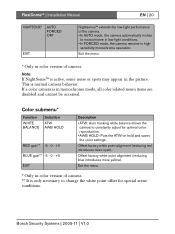
...; In FORCED mode, the camera remains in monochrome mode, all color related menu items are disabled and cannot be accessed. FlexiDomeVF | Installation Manual EN | 20 NIGHTSENSE* AUTO FORCED OFF EXIT Nightsense™ extends the low-light performance of camera. ** It is only necessary to change the white point...camera is normal camera behavior. Note If NightSense™ is active, some noise or spots may appear in color version of camera. Bosch Security Systems | 2005-11 | V1.0 Exit the menu * Only in the picture. Offset factory white point alignment (reducing blue introduces more cyan)....
...; In FORCED mode, the camera remains in monochrome mode, all color related menu items are disabled and cannot be accessed. FlexiDomeVF | Installation Manual EN | 20 NIGHTSENSE* AUTO FORCED OFF EXIT Nightsense™ extends the low-light performance of camera. ** It is only necessary to change the white point...camera is normal camera behavior. Note If NightSense™ is active, some noise or spots may appear in color version of camera. Bosch Security Systems | 2005-11 | V1.0 Exit the menu * Only in the picture. Offset factory white point alignment (reducing blue introduces more cyan)....
Installation Instructions
Page 21
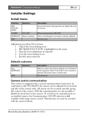
.... Adjust the lens focus now. Allow 5 seconds for all settings for the camera to fully open the iris. FlexiDomeVF | Installation Manual EN | 21 Installer Settings Install menu Function SET FOCUS NOW COMM DEFAULTS EXIT Selection ON, OFF Select submenu Description Forces the lens ...to optimize the picture after a mode reset. A confirmation screen appears. Lock the focus locking screw. 5. Bosch Security Systems | 2005-11 | V1.0 SET BACK FOCUS NOW is equipped with VP-CFGSFT, the camera can only be accessed remotely giving...
.... Adjust the lens focus now. Allow 5 seconds for all settings for the camera to fully open the iris. FlexiDomeVF | Installation Manual EN | 21 Installer Settings Install menu Function SET FOCUS NOW COMM DEFAULTS EXIT Selection ON, OFF Select submenu Description Forces the lens ...to optimize the picture after a mode reset. A confirmation screen appears. Lock the focus locking screw. 5. Bosch Security Systems | 2005-11 | V1.0 SET BACK FOCUS NOW is equipped with VP-CFGSFT, the camera can only be accessed remotely giving...

Installation Instructions
Page 22
...Manual Technical specification EN | 22 Type number Standard Active pixels Min illumination Resolution Rated supply voltage VDC445V0x-10 VDC445V0x-20 VDC345V0x-10 VDC345V0x-20 PAL NTSC CCIR EIA 752x582 768x492 752x582 768x492 < 1.0 lux < 0.4 lux (NightSense On) < 0.2 lux 540 TVL 570 TVL 24 VAC or 12 VDC 12-28 VAC (50/60 Hz) 11-36 VDC...(20 dB) or Off selectable Sharpness enhancement BLC On or Off selectable Automatic 2500 - 9000K (with AWB hold mode) Integrated Varifocal with DC iris < 5 W 58 x 66 x 122 mm (HxWxL) 550g -10° to 45° C OSD with softkey operation Bosch ...
...Manual Technical specification EN | 22 Type number Standard Active pixels Min illumination Resolution Rated supply voltage VDC445V0x-10 VDC445V0x-20 VDC345V0x-10 VDC345V0x-20 PAL NTSC CCIR EIA 752x582 768x492 752x582 768x492 < 1.0 lux < 0.4 lux (NightSense On) < 0.2 lux 540 TVL 570 TVL 24 VAC or 12 VDC 12-28 VAC (50/60 Hz) 11-36 VDC...(20 dB) or Off selectable Sharpness enhancement BLC On or Off selectable Automatic 2500 - 9000K (with AWB hold mode) Integrated Varifocal with DC iris < 5 W 58 x 66 x 122 mm (HxWxL) 550g -10° to 45° C OSD with softkey operation Bosch ...