Instruction Manual
Page 1
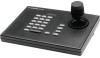
LTC 5136 Series Instruction Manual EN AutoDome® Controller
LTC 5136 Series Instruction Manual EN AutoDome® Controller
Instruction Manual
Page 8
LTC 5136 Series | Instruction Manual | Contents EN | 8 Table of Contents Important Safeguards 2 FCC Information 2 1 UNPACKING 9 2 SERVICE 9 3 DESCRIPTION 9 3.1 Power 9 4 INSTALLATION 10 4.1 General 10 4.2 Installation using Biphase Code 10 4.3 Installation using RS-232 Data Direct to Camera Site 11 4.4 Installation using an RS-232 Data Transmission Link to a Biphase Camera Site 12 4.5 AutoDome Camera or Receiver...
LTC 5136 Series | Instruction Manual | Contents EN | 8 Table of Contents Important Safeguards 2 FCC Information 2 1 UNPACKING 9 2 SERVICE 9 3 DESCRIPTION 9 3.1 Power 9 4 INSTALLATION 10 4.1 General 10 4.2 Installation using Biphase Code 10 4.3 Installation using RS-232 Data Direct to Camera Site 11 4.4 Installation using an RS-232 Data Transmission Link to a Biphase Camera Site 12 4.5 AutoDome Camera or Receiver...
Instruction Manual
Page 9
... equivalent). 3.1 Power The model number and operating voltage are designed for the following items: • LTC 5136/61 or LTC 5136/51 Desktop Controller. • Interface unit. • Power supply. • Power supply cable. • One (1) 3 m (10 ft) cable with the Bosch AutoDome Series cameras. NOTE: Grounded wrist straps must be unpacked and handled carefully. Service Center for...
... equivalent). 3.1 Power The model number and operating voltage are designed for the following items: • LTC 5136/61 or LTC 5136/51 Desktop Controller. • Interface unit. • Power supply. • Power supply cable. • One (1) 3 m (10 ft) cable with the Bosch AutoDome Series cameras. NOTE: Grounded wrist straps must be unpacked and handled carefully. Service Center for...
Instruction Manual
Page 10
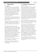
...simplex link operating at 9600 baud. select the type of the interface unit are no video connections to RS-232 Series AutoDome cameras or RS-232 Allegiant Receiver/Driver units, the installation is not important; Note that supplied 3 m (10 ft... are provided for both power and data connections. Bosch Security Systems | 04 September 2003 Plug the power supply into Allegiant biphase control code. LTC 5136 Series | Instruction Manual | Installation EN | 10 4 INSTALLATION 4.1 General The desktop Controller unit should be located in a convenient location near...
...simplex link operating at 9600 baud. select the type of the interface unit are no video connections to RS-232 Series AutoDome cameras or RS-232 Allegiant Receiver/Driver units, the installation is not important; Note that supplied 3 m (10 ft... are provided for both power and data connections. Bosch Security Systems | 04 September 2003 Plug the power supply into Allegiant biphase control code. LTC 5136 Series | Instruction Manual | Installation EN | 10 4 INSTALLATION 4.1 General The desktop Controller unit should be located in a convenient location near...
Instruction Manual
Page 11
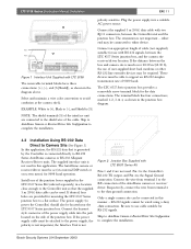
...the Controller unit so that is generated by the Controller is not used in the junction box diagram. 4.3 Installation Using RS-232 Data Direct to a flat surface. Install one of the cable. If the power supply cable must be wired using a daisy chain connection. Bosch ...attached to support an RS-232 simplex transmission rate of the AutoDome camera or receiver/ driver. If desired, four holes are connected to complete the installation. the Interface Unit is not Figure 2 Junction Box Supplied with LTC 5136 The removable terminal blocks have three connections: (+), (-), and (S...
...the Controller unit so that is generated by the Controller is not used in the junction box diagram. 4.3 Installation Using RS-232 Data Direct to a flat surface. Install one of the cable. If the power supply cable must be wired using a daisy chain connection. Bosch ...attached to support an RS-232 simplex transmission rate of the AutoDome camera or receiver/ driver. If desired, four holes are connected to complete the installation. the Interface Unit is not Figure 2 Junction Box Supplied with LTC 5136 The removable terminal blocks have three connections: (+), (-), and (S...
Instruction Manual
Page 12
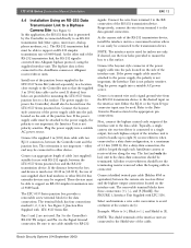
...Controller unit so that is generated by the Controller...LTC...LTC...LTC 5136. Connect the bayonet style connector of the RS-232 transmission device. the Interface Unit is connected directly to an RS-232 transmission link (fiber optics, microwave, dial-up to eight (8) receiver/drivers when connected in the daisy chain connection should have three connections: (+), (-), and (S [Shield]). Next, connect the biphase control... LTC 5136 ...LTC...LTC 8557 Series junction box and the RS-232 transmission device. either end may be connected to the AutoDome...Controller unit and the junction box....
...Controller unit so that is generated by the Controller...LTC...LTC...LTC 5136. Connect the bayonet style connector of the RS-232 transmission device. the Interface Unit is connected directly to an RS-232 transmission link (fiber optics, microwave, dial-up to eight (8) receiver/drivers when connected in the daisy chain connection should have three connections: (+), (-), and (S [Shield]). Next, connect the biphase control... LTC 5136 ...LTC...LTC 8557 Series junction box and the RS-232 transmission device. either end may be connected to the AutoDome...Controller unit and the junction box....
Instruction Manual
Page 13
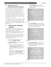
...camera site are viewing (i.e. Call up the camera to the screen you want to the Controller. Figure FA2 4. Set the address of how to enter the addressing mode. Figure FA1... Make sure you are viewing the camera that will be used . Bosch Security Systems | 04 September 2003 Figure FA3 The AutoDome being Fast Addressed has the switch address (thumbwheel) set . CAMERA-3-ENTER...Address feature. This is used to the unit. LTC 5136 Series | Instruction Manual | Setting Fast Addess Feature EN | 13 4.5 AutoDome Camera or Receiver/Driver Site Configuration Follow the ...
...camera site are viewing (i.e. Call up the camera to the screen you want to the Controller. Figure FA2 4. Set the address of how to enter the addressing mode. Figure FA1... Make sure you are viewing the camera that will be used . Bosch Security Systems | 04 September 2003 Figure FA3 The AutoDome being Fast Addressed has the switch address (thumbwheel) set . CAMERA-3-ENTER...Address feature. This is used to the unit. LTC 5136 Series | Instruction Manual | Setting Fast Addess Feature EN | 13 4.5 AutoDome Camera or Receiver/Driver Site Configuration Follow the ...
Instruction Manual
Page 14
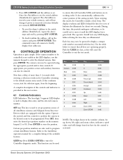
LTC 5136 Series | Instruction Manual | Controller Operation EN | 14 5. The camera can also be entered. Press SET, then enter the desired pre-position number on how far the control is removed or factory defaults are equipped with that all Controller LEDs and buttons are operating properly. to ensure that a delay of the controls and indicators is provided...
LTC 5136 Series | Instruction Manual | Controller Operation EN | 14 5. The camera can also be entered. Press SET, then enter the desired pre-position number on how far the control is removed or factory defaults are equipped with that all Controller LEDs and buttons are operating properly. to ensure that a delay of the controls and indicators is provided...
Instruction Manual
Page 15
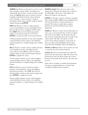
... CLEAR key: This key is used to correct an error when selecting a camera number. Rotation of the AutoDome cameras and Allegiant Series receiver/drivers. Bosch Security Systems | 04 September 2003 NUMERIC keypad: These keys are also used to enter numeric data. Press...AutoDome features. SHOT key: This key is used to recall pre-position scenes of the joystick left or right will tilt the camera up or down . If there is numeric data in the LED display, the first push clears the entire Controller, back to clear incorrect data without leaving the current mode. LTC 5136...
... CLEAR key: This key is used to correct an error when selecting a camera number. Rotation of the AutoDome cameras and Allegiant Series receiver/drivers. Bosch Security Systems | 04 September 2003 NUMERIC keypad: These keys are also used to enter numeric data. Press...AutoDome features. SHOT key: This key is used to recall pre-position scenes of the joystick left or right will tilt the camera up or down . If there is numeric data in the LED display, the first push clears the entire Controller, back to clear incorrect data without leaving the current mode. LTC 5136...
Instruction Manual
Page 16
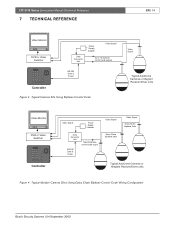
LTC 5136 Series | Instruction Manual | Technical Reference 7 TECHNICAL REFERENCE EN | 16 Video Monitor DVR or Video Switcher Data Converter Unit Power Supply Adapter Video Signal Up to 16 biphase control code outputs RS-232 Data & Power Controller Figure 3 Typical Camera Site Using Biphase Control Code Video Signal Typical AutoDome Cameras or Allegiant Receiver/Driver units Video Monitor...
LTC 5136 Series | Instruction Manual | Technical Reference 7 TECHNICAL REFERENCE EN | 16 Video Monitor DVR or Video Switcher Data Converter Unit Power Supply Adapter Video Signal Up to 16 biphase control code outputs RS-232 Data & Power Controller Figure 3 Typical Camera Site Using Biphase Control Code Video Signal Typical AutoDome Cameras or Allegiant Receiver/Driver units Video Monitor...
Instruction Manual
Page 17
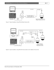
LTC 5136 Series | Instruction Manual | Technical Reference EN | 17 Video Monitor Power Supply Adapter Video Signal Controller RS-232 Data & Power LTC 8557 Junction Box RS-232 Cable or Communication Link Typical AutoDome Camera or Allegiant Receiver/Driver unit Figure 5 Typical Installation Using RS-232 Model... Adapter Data Converter Unit Biphase Data RS-232 Data Video Signal Biphase Data LTC 8557 Junction Box Controller RS-232 Data & Power RS-232 Cable or Communication Link Typical AutoDome Cameras or Allegiant Receiver/Driver units Figure 6 Typical Installation Using RS-232 ...
LTC 5136 Series | Instruction Manual | Technical Reference EN | 17 Video Monitor Power Supply Adapter Video Signal Controller RS-232 Data & Power LTC 8557 Junction Box RS-232 Cable or Communication Link Typical AutoDome Camera or Allegiant Receiver/Driver unit Figure 5 Typical Installation Using RS-232 Model... Adapter Data Converter Unit Biphase Data RS-232 Data Video Signal Biphase Data LTC 8557 Junction Box Controller RS-232 Data & Power RS-232 Cable or Communication Link Typical AutoDome Cameras or Allegiant Receiver/Driver units Figure 6 Typical Installation Using RS-232 ...
