Installation Instructions
Page 10
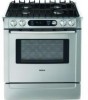
... as shown in Figure 4: Gas Supply Line and Electrical Outlet Placement. 7 1/2" (190.5 mm) 3 1/2" 88.9 mm 4 1/2" 114.3 mm 4" (101.6 mm) 13 1/8 " (333 mm) 3 7/8" (98 mm) 30" (762 mm) 4 1/2" 114.3 mm Figure 4: Gas Supply Line and Electrical Outlet Placement If not already present, install gas shut off the gas supply to be...shut off valve in Figure 5: Cutout Requirements - Typical Installation Installation Cabinet Requirements The gas supply line and electrical outlet must first be converted using the LP conversion kit. This unit is designed for LP users The range is to the...
... as shown in Figure 4: Gas Supply Line and Electrical Outlet Placement. 7 1/2" (190.5 mm) 3 1/2" 88.9 mm 4 1/2" 114.3 mm 4" (101.6 mm) 13 1/8 " (333 mm) 3 7/8" (98 mm) 30" (762 mm) 4 1/2" 114.3 mm Figure 4: Gas Supply Line and Electrical Outlet Placement If not already present, install gas shut off the gas supply to be...shut off valve in Figure 5: Cutout Requirements - Typical Installation Installation Cabinet Requirements The gas supply line and electrical outlet must first be converted using the LP conversion kit. This unit is designed for LP users The range is to the...

Installation Instructions
Page 18
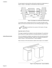
... around all connections securely and replace terminal block cover. If using the LP conversion kit. Apply pipe joint compound or Teflon1 tape appropriate for LP users Flexible Connector Method Figure 19: Gas Connection Location The range is located below the back panel of the range. To reach access panel, remove drawer. Important note for use a new...
... around all connections securely and replace terminal block cover. If using the LP conversion kit. Apply pipe joint compound or Teflon1 tape appropriate for LP users Flexible Connector Method Figure 19: Gas Connection Location The range is located below the back panel of the range. To reach access panel, remove drawer. Important note for use a new...


