Installation Instructions
Page 3
...3 Installation 4 Determine the Installation Type 4 Pre-Assembly of Combination Ovens Prior to Installation 4 Electrical Installation 7 Installing the Oven Unit into the Wall Cabinet 8 For Best Installation ...8 Removing the Bottom Hinge Oven Door . . . . 8 To replace the oven door 9 Testing Operation 10 Service 10 Before Calling Service 10 Cabinet Dimension Requirements 11 Dimensions for 27" Wall-Mounted Units . . . 11 Dimensions for 30" Wall-Mounted Units . 12 This Bosch...
...3 Installation 4 Determine the Installation Type 4 Pre-Assembly of Combination Ovens Prior to Installation 4 Electrical Installation 7 Installing the Oven Unit into the Wall Cabinet 8 For Best Installation ...8 Removing the Bottom Hinge Oven Door . . . . 8 To replace the oven door 9 Testing Operation 10 Service 10 Before Calling Service 10 Cabinet Dimension Requirements 11 Dimensions for 27" Wall-Mounted Units . . . 11 Dimensions for 30" Wall-Mounted Units . 12 This Bosch...
Installation Instructions
Page 4
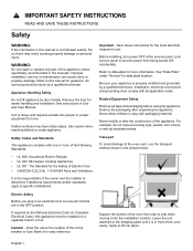
...to data plate for the Safety of Electric Fans • CAN/CSA-C22.2 No. 113-M1984 Fans and Ventilators It is properly installed and grounded by the National Electrical Code (or Canadian Electrical Code), this appliance must comply with packaging material. For example, do not...INSTRUCTIONS READ AND SAVE THESE INSTRUCTIONS Safety WARNING: If the information in front of the oven cavity, ready to lift into the installation location. Improper installation, service or maintenance can cause injury or property damage. Refer to move. Remove the door for guidance. Mark it into place...
...to data plate for the Safety of Electric Fans • CAN/CSA-C22.2 No. 113-M1984 Fans and Ventilators It is properly installed and grounded by the National Electrical Code (or Canadian Electrical Code), this appliance must comply with packaging material. For example, do not...INSTRUCTIONS READ AND SAVE THESE INSTRUCTIONS Safety WARNING: If the information in front of the oven cavity, ready to lift into the installation location. Improper installation, service or maintenance can cause injury or property damage. Refer to move. Remove the door for guidance. Mark it into place...
Installation Instructions
Page 5
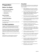
... in step 2 above. ___ 11. Note: Do not attempt to the installation manual for content regarding Safety, Cabinet Dimensions, Removing Packaging, Electrical Installation, Testing the Installation and Customer Service. ___ 3. This can help you have three or more ... door(s) removed in front of the carton (using Philips screwdriver). ___ 10. Consult the complete installation instructions and follow the instructions provided for an improved installation experience. INSTALLER - English 2 Preparation Before You Begin Tools and Parts Needed • Phillips head screwdriver •...
... in step 2 above. ___ 11. Note: Do not attempt to the installation manual for content regarding Safety, Cabinet Dimensions, Removing Packaging, Electrical Installation, Testing the Installation and Customer Service. ___ 3. This can help you have three or more ... door(s) removed in front of the carton (using Philips screwdriver). ___ 10. Consult the complete installation instructions and follow the instructions provided for an improved installation experience. INSTALLER - English 2 Preparation Before You Begin Tools and Parts Needed • Phillips head screwdriver •...
Installation Instructions
Page 6
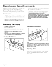
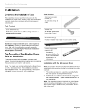
...Remove cardboard box. • Remove all top and side cardboard and Styrofoam braces. • Place oven in front of the opening to be installed. • Unscrew unit from Left and Right Brackets as show in line with the bottom and side of cabinets where it is to provide ...is in "Left and Right Packaging Bracket Removal." Please consult the "Cabinet Dimension Requirements" section at the end of a cabinet run. • Installation of this installation manual for your particular model. All models require: • 1/4" (6.4 mm) space between the side of the oven and an adjacent wall or...
...Remove cardboard box. • Remove all top and side cardboard and Styrofoam braces. • Place oven in front of the opening to be installed. • Unscrew unit from Left and Right Brackets as show in line with the bottom and side of cabinets where it is to provide ...is in "Left and Right Packaging Bracket Removal." Please consult the "Cabinet Dimension Requirements" section at the end of a cabinet run. • Installation of this installation manual for your particular model. All models require: • 1/4" (6.4 mm) space between the side of the oven and an adjacent wall or...
Installation Instructions
Page 7
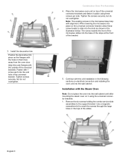
... attached to the oven spaced to all ovens. The parts contained in the square tube parts box are interchangeable for the installation of single ovens, double ovens and combination ovens (a single oven combined with with mounting screws in a red bag within the...oven). Combo service slide assembly (2)* * This part is positioned to accomodate attachment of a microwave. Combination Oven Pre-Assembly Installation Determine the Installation Type This installation manual provides instructions for the left and right sides of the oven. Tighten screws securely, but do not overtighten...
... attached to the oven spaced to all ovens. The parts contained in the square tube parts box are interchangeable for the installation of single ovens, double ovens and combination ovens (a single oven combined with with mounting screws in a red bag within the...oven). Combo service slide assembly (2)* * This part is positioned to accomodate attachment of a microwave. Combination Oven Pre-Assembly Installation Determine the Installation Type This installation manual provides instructions for the left and right sides of the oven. Tighten screws securely, but do not overtighten...
Installation Instructions
Page 8
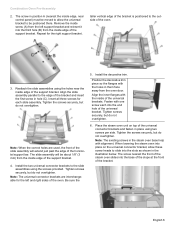
...screws securely, but do not overtighten. When lowering the microwave into the slots as shown in the microwave base help with the unit installation in the tops of the universal brackets. Remove the six screws holding the combo service slide assemblies to slide into place on it using... per side. 3. Use a magnetic screwdriver bit to reach the screws through the large holes in the following sections on electrical connection and installing the oven unit into the wall cabinet until after mounting the steam oven on the universal connector bracket, allow these screw heads to the ...
...screws securely, but do not overtighten. When lowering the microwave into the slots as shown in the microwave base help with the unit installation in the tops of the universal brackets. Remove the six screws holding the combo service slide assemblies to slide into place on it using... per side. 3. Use a magnetic screwdriver bit to reach the screws through the large holes in the following sections on electrical connection and installing the oven unit into the wall cabinet until after mounting the steam oven on the universal connector bracket, allow these screw heads to the ...
Installation Instructions
Page 9
... existing screws in them face away from the left and right sides of the bracket. Insert all three screws for the right support bracket. Install the two universal connector brackets to the outside of the universal bracket. Tighten screws securely, but do not overtighten. 6. Repeat for each into... the base of the slope at the front of the oven. Install the decorative trim. The screw nearest the front of the steam oven slides into the end hole of the oven. 3. Combination Oven Pre-Assembly...
... existing screws in them face away from the left and right sides of the bracket. Insert all three screws for the right support bracket. Install the two universal connector brackets to the outside of the universal bracket. Tighten screws securely, but do not overtighten. 6. Repeat for each into... the base of the slope at the front of the oven. Install the decorative trim. The screw nearest the front of the steam oven slides into the end hole of the oven. 3. Combination Oven Pre-Assembly...
Installation Instructions
Page 10
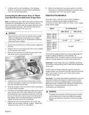
... junction box. Replace the oven mounted junction box cover and tighten the two screws holding it clicks into the wall cabinet. installation, electrical connections and grounding must be connected to the main power supply. English 7 This must comply with the unit electrical ... Oven Electrical Conduit to the Single Oven" showing electrical connection of the combination unit components. 9 WARNING Complete the connection of this installation instruction manual are dual rated, designed to be done prior to supplying electric power to the white neutral electrical supply wire. Continue...
... junction box. Replace the oven mounted junction box cover and tighten the two screws holding it clicks into the wall cabinet. installation, electrical connections and grounding must be connected to the main power supply. English 7 This must comply with the unit electrical ... Oven Electrical Conduit to the Single Oven" showing electrical connection of the combination unit components. 9 WARNING Complete the connection of this installation instruction manual are dual rated, designed to be done prior to supplying electric power to the white neutral electrical supply wire. Continue...
Installation Instructions
Page 11
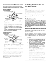
... black wires green or bare wire green wire UL listed connector white wires cable from hinge bracket snapping closed - For ease of installation, some models). The conduit cable, where connected at the oven, swivels. Removing the Bottom Hinge Oven Door Important: Do not...wire in junction box. Combination units (ovens with lifting the unit into the Wall Cabinet Note: Before installing the oven, be difficult for correct installation. For Best Installation The double and combination ovens can be sure to verify the cabinet dimensions and electrical connections.Check that...
... black wires green or bare wire green wire UL listed connector white wires cable from hinge bracket snapping closed - For ease of installation, some models). The conduit cable, where connected at the oven, swivels. Removing the Bottom Hinge Oven Door Important: Do not...wire in junction box. Combination units (ovens with lifting the unit into the Wall Cabinet Note: Before installing the oven, be difficult for correct installation. For Best Installation The double and combination ovens can be sure to verify the cabinet dimensions and electrical connections.Check that...
Installation Instructions
Page 12
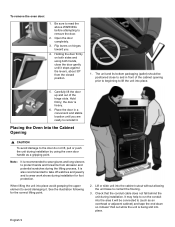
... damaging it . Lift or slide unit into place avoid grasping the upper element to the door do not lift, pull or push the unit during installation. English 9 Holding the door firmly on hinges toward you are ready to and in a convenient and stable location unitl you . 4. Open the door ...an overhead or adjacent cabinet) and tape the end down so it stops against the levers, about 30º from abrasion and potential scratches during installation for the correct lifting point. 2. The unit and its bottom packaging (pallet) should be connected to remove the door. 2. Be sure to ...
... damaging it . Lift or slide unit into place avoid grasping the upper element to the door do not lift, pull or push the unit during installation. English 9 Holding the door firmly on hinges toward you are ready to and in a convenient and stable location unitl you . 4. Open the door ...an overhead or adjacent cabinet) and tape the end down so it stops against the levers, about 30º from abrasion and potential scratches during installation for the correct lifting point. 2. The unit and its bottom packaging (pallet) should be connected to remove the door. 2. Be sure to ...
Installation Instructions
Page 13
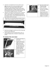
...hinges sit correctly in place. If necessary, guide the flexible conduit into the slots. Use two of the cabinet). Insert screws and tighten firmly. Install supplied screws through tap holes in , leave about 1 inch extending from the closed position and insert hinges into the wall or cabinet access hole...is flush with holes at a 30º angle from the front of the screws provided in both hands. 2. English 10 Do not overtighten. 3. Install the oven bottom trim while the door is removed and the unit is correctly and securely in the slots. 4. To replace the oven door: 1. ...
...hinges sit correctly in place. If necessary, guide the flexible conduit into the slots. Use two of the cabinet). Insert screws and tighten firmly. Install supplied screws through tap holes in , leave about 1 inch extending from the closed position and insert hinges into the wall or cabinet access hole...is flush with holes at a 30º angle from the front of the screws provided in both hands. 2. English 10 Do not overtighten. 3. Install the oven bottom trim while the door is removed and the unit is correctly and securely in the slots. 4. To replace the oven door: 1. ...
Installation Instructions
Page 14
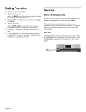
See the Use and Care Manual for troubleshooting information. Set the SELF CLEAN mode. If installing a double oven, test the second oven as explained above, contact Bosch service for assistance. If any of the control panel. Select the BAKE mode. Test the door lock. The data plate ...is complete at the front of the manual. Data Plate English 11 Otherwise, the installation is located on the appliance when...
See the Use and Care Manual for troubleshooting information. Set the SELF CLEAN mode. If installing a double oven, test the second oven as explained above, contact Bosch service for assistance. If any of the control panel. Select the BAKE mode. Test the door lock. The data plate ...is complete at the front of the manual. Data Plate English 11 Otherwise, the installation is located on the appliance when...
Installation Instructions
Page 15
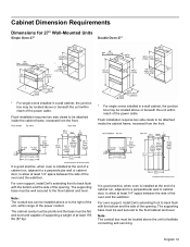
... the oven and the wall/door. Cabinet Dimension Requirements Dimensions for 27" Wall-Mounted Units Single Oven 27" Double Oven 27" * For single ovens installed in a wall cabinet, the junction box may be located above or beneath the unit within reach of the power cable. English 12 For oven support...the base must be well secured to the right of the unit, within range of the power conduit. It is good practice, when oven is installed at least 1/4" space between the side of the opening . The supporting base must be located above or beneath the unit within reach of at ...
... the oven and the wall/door. Cabinet Dimension Requirements Dimensions for 27" Wall-Mounted Units Single Oven 27" Double Oven 27" * For single ovens installed in a wall cabinet, the junction box may be located above or beneath the unit within reach of the power cable. English 12 For oven support...the base must be well secured to the right of the unit, within range of the power conduit. It is good practice, when oven is installed at least 1/4" space between the side of the opening . The supporting base must be located above or beneath the unit within reach of at ...

Installation Instructions
Page 16
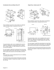
... back wall and the right rear of the opening . The supporting base must be well secured to the floor/cabinet and level. For oven support, install 2x4's extending front to allow at least 1/4" space between the side of the oven and the wall/door. The cabinet cavity must be plumb and... the base must be flat and level and capable of supporting a weight of the opening . Flush installation requires two side cleats to back flush with the bottom and the side of at the end of a cabinet run , adjacent to a perpendicular wall or...
... back wall and the right rear of the opening . The supporting base must be well secured to the floor/cabinet and level. For oven support, install 2x4's extending front to allow at least 1/4" space between the side of the oven and the wall/door. The cabinet cavity must be plumb and... the base must be flat and level and capable of supporting a weight of the opening . Flush installation requires two side cleats to back flush with the bottom and the side of at the end of a cabinet run , adjacent to a perpendicular wall or...
Installation Instructions
Page 17
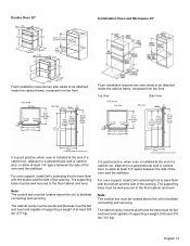
...: The conduit box must be attached inside the cabinet frame, recessed from the front. Top View Side View It is good practice, when oven is installed at the end of a cabinet run , adjacent to a perpendicular wall or cabinet door, to allow at least 1/4" space between the side of the oven and... box must be located above the unit to allow at least 1/4" space between the side of the oven and the wall/door. For oven support, install 2x4's extending front to back flush with the bottom and the side of at least 310 lbs (141 kg). The cabinet cavity must be plumb...
...: The conduit box must be attached inside the cabinet frame, recessed from the front. Top View Side View It is good practice, when oven is installed at the end of a cabinet run , adjacent to a perpendicular wall or cabinet door, to allow at least 1/4" space between the side of the oven and... box must be located above the unit to allow at least 1/4" space between the side of the oven and the wall/door. For oven support, install 2x4's extending front to back flush with the bottom and the side of at least 310 lbs (141 kg). The cabinet cavity must be plumb...
Installation Instructions
Page 18
... two side cleats to be attached inside the cabinet frame, recessed from the front. It is good practice, when oven is installed at the end of the oven and the wall/door. The supporting base must be located above the unit to facilitate connecting and servicing. Note: ... conduit box must be well secured to the floor/cabinet and level. English 15 Combination Oven and Steam Oven 30" Single Oven, Undercounter 30" Flush installation requires two side cleats to be attached inside the cabinet frame, recessed from the front. The supporting base must be flat and level and capable...
... two side cleats to be attached inside the cabinet frame, recessed from the front. It is good practice, when oven is installed at the end of the oven and the wall/door. The supporting base must be located above the unit to facilitate connecting and servicing. Note: ... conduit box must be well secured to the floor/cabinet and level. English 15 Combination Oven and Steam Oven 30" Single Oven, Undercounter 30" Flush installation requires two side cleats to be attached inside the cabinet frame, recessed from the front. The supporting base must be flat and level and capable...
Supplement
Page 2
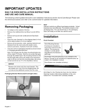
...sides) Note: Different models use different packaging materials. The unit should stay on the shipping base) in the illustration below is already installed. The bottom trim pictured below .) NOTICE Remove one screw that goes through the slotted hole in order to be lifted into cabinet ...cabinet where it is to lift the unit from packaging brackets as shown below in the installation manual. Installation Parts Provided Oven Mounting Screws 8 screws are included to secure the oven trim to be installed. • Remove all torx head (T-20 size). English 1 Actual brackets may look ...
...sides) Note: Different models use different packaging materials. The unit should stay on the shipping base) in the illustration below is already installed. The bottom trim pictured below .) NOTICE Remove one screw that goes through the slotted hole in order to be lifted into cabinet ...cabinet where it is to lift the unit from packaging brackets as shown below in the installation manual. Installation Parts Provided Oven Mounting Screws 8 screws are included to secure the oven trim to be installed. • Remove all torx head (T-20 size). English 1 Actual brackets may look ...
Supplement
Page 4
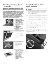
... 4. This illustration shows a detailed view of protective foam padding to avoid damage to grip from the closed position. Remove Prior to Install Important: Do not attempt to remove the door. 2. See the illustration following for the correct lifting point for a bottom hinge double...3 Removing the door lightens the unit significantly and provides easier access to protect hands and forearms from abrasion and potential scratches during installation for lift points. 5. Removing and replacing the door are found only on both hands, close the door gently until it stops...
... 4. This illustration shows a detailed view of protective foam padding to avoid damage to grip from the closed position. Remove Prior to Install Important: Do not attempt to remove the door. 2. See the illustration following for the correct lifting point for a bottom hinge double...3 Removing the door lightens the unit significantly and provides easier access to protect hands and forearms from abrasion and potential scratches during installation for lift points. 5. Removing and replacing the door are found only on both hands, close the door gently until it stops...
Supplement
Page 5
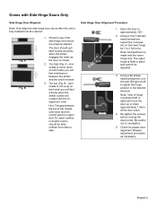
...) will feel interference between the top of hinge movement (left to 2 full turns. English 4 Too high (Fig. Repeat adjustment procedure as the door is fully installed into contact with the realignment roller. Open the door to see if the side hinge oven doors are properly aligned. Fig.
...) will feel interference between the top of hinge movement (left to 2 full turns. English 4 Too high (Fig. Repeat adjustment procedure as the door is fully installed into contact with the realignment roller. Open the door to see if the side hinge oven doors are properly aligned. Fig.
Supplement
Page 6
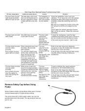
.... The door does not close While trying to open the The door To open smoothly and pull itself closed opens without incident. striker. Check the installation of the probe. A firm push may be pushed too far inwards. The door does not close the door completely and while closed, push in ...and may also appear to stick while pulling the door open up. smoothly. Once closed, the door may properly with the unit's side trim. The installation is too procedure to raise the handle side of the inner door (on the door handle until the door closes smoothly. Try to move the...
.... The door does not close While trying to open the The door To open smoothly and pull itself closed opens without incident. striker. Check the installation of the probe. A firm push may be pushed too far inwards. The door does not close the door completely and while closed, push in ...and may also appear to stick while pulling the door open up. smoothly. Once closed, the door may properly with the unit's side trim. The installation is too procedure to raise the handle side of the inner door (on the door handle until the door closes smoothly. Try to move the...


