
Operation Manual
Page 3
... Camera settings Schedule settings Display settings Event settings Network settings System settings 4 Recording 4.1 Instant Recording 5 Search and playback 5.1 Playback 5.2 Search 5.3 Functions available during playback Bosch Security Systems User Manual Table of contents | en 1 3 3 4 4 9 9 10 11 13 14 17 17 18 18 18 19 19 19 20 21 22 23 24 25 27...
... Camera settings Schedule settings Display settings Event settings Network settings System settings 4 Recording 4.1 Instant Recording 5 Search and playback 5.1 Playback 5.2 Search 5.3 Functions available during playback Bosch Security Systems User Manual Table of contents | en 1 3 3 4 4 9 9 10 11 13 14 17 17 18 18 18 19 19 19 20 21 22 23 24 25 27...
Operation Manual
Page 4
2 en | Table of contents 5.4 EXPORT 6 Control Center 6.1 PC minimum Requirements 6.2 Control Center installation 6.3 Connecting to the DVR 6.4 Main screen of DVR Control Center Program 6.5 Live Mode 6.6 Search mode 6.7 Remote Setup mode 6.8 Remote Export Settings 7 Additional programs 7.1 Alarm Notifier program 7.2 Main Screen of Alarm Noti&#... 83 83 83 86 88 93 97 107 109 109 110 112 115 119 119 122 124 125 128 130 133 F01U | 2.0 | 2008.12 User Manual Bosch Security Systems
2 en | Table of contents 5.4 EXPORT 6 Control Center 6.1 PC minimum Requirements 6.2 Control Center installation 6.3 Connecting to the DVR 6.4 Main screen of DVR Control Center Program 6.5 Live Mode 6.6 Search mode 6.7 Remote Setup mode 6.8 Remote Export Settings 7 Additional programs 7.1 Alarm Notifier program 7.2 Main Screen of Alarm Noti&#... 83 83 83 86 88 93 97 107 109 109 110 112 115 119 119 122 124 125 128 130 133 F01U | 2.0 | 2008.12 User Manual Bosch Security Systems

Operation Manual
Page 5
... the equipment; - The power cord is provided, or the manufacturer's instructions have power supplied to the equipment has occurred, such as a wet location. Bosch Security Systems User Manual F01U | 2.0 | 2008.12 Follow any instructions provided with the latest versions of fire or electrical shock, do not expose this unit near water, for...
... the equipment; - The power cord is provided, or the manufacturer's instructions have power supplied to the equipment has occurred, such as a wet location. Bosch Security Systems User Manual F01U | 2.0 | 2008.12 Follow any instructions provided with the latest versions of fire or electrical shock, do not expose this unit near water, for...

Operation Manual
Page 6
.... Medium risk: Indicates a potentially hazardous situation. Use only with applicable local codes. 17. F01U | 2.0 | 2008.12 User Manual Bosch Security Systems Replacement parts - Be sure the service technician uses replacement parts specified by the manufacturer. Only use caution and care when ... the cart/unit combination to important instructions accompanying the unit. When a cart is used, use attachments/accessories specified by Bosch, could result in minor or moderate injury. Unauthorized substitutions could void the warranty and cause fire, electrical shock, or other...
.... Medium risk: Indicates a potentially hazardous situation. Use only with applicable local codes. 17. F01U | 2.0 | 2008.12 User Manual Bosch Security Systems Replacement parts - Be sure the service technician uses replacement parts specified by the manufacturer. Only use caution and care when ... the cart/unit combination to important instructions accompanying the unit. When a cart is used, use attachments/accessories specified by Bosch, could result in minor or moderate injury. Unauthorized substitutions could void the warranty and cause fire, electrical shock, or other...
Operation Manual
Page 7
... is located inside the unit enclosure. Follow proper safety precautions such as the main disconnect device for the grounding electrode. Bosch Security Systems User Manual F01U | 2.0 | 2008.12 Replace only with one way. If unable to insert the plug fully into a grounded power outlet... only. Bosch has a strong commitment towards the environment. This safety feature allows the plug to beam. Avoid exposure to fit into the ...
... is located inside the unit enclosure. Follow proper safety precautions such as the main disconnect device for the grounding electrode. Bosch Security Systems User Manual F01U | 2.0 | 2008.12 Replace only with one way. If unable to insert the plug fully into a grounded power outlet... only. Bosch has a strong commitment towards the environment. This safety feature allows the plug to beam. Avoid exposure to fit into the ...

Operation Manual
Page 8
... as outlined in accordance with NEC725 and NEC800 (CEC Rule 16-224 and CEC Section 60). F01U | 2.0 | 2008.12 User Manual Bosch Security Systems Power disconnect - Do not place this product. SELV - These limits are Safety Extra Low Voltage (SELV) circuits. Excessive ... not tested the performance or reliability of the security or signaling aspects of this equipment does cause harmful interference to part 15 of Bosch Security Systems and is inherent to correct the interference by copyright. 6 en | Safety Digital Video Recorder Moving - The installation for...
... as outlined in accordance with NEC725 and NEC800 (CEC Rule 16-224 and CEC Section 60). F01U | 2.0 | 2008.12 User Manual Bosch Security Systems Power disconnect - Do not place this product. SELV - These limits are Safety Extra Low Voltage (SELV) circuits. Excessive ... not tested the performance or reliability of the security or signaling aspects of this equipment does cause harmful interference to part 15 of Bosch Security Systems and is inherent to correct the interference by copyright. 6 en | Safety Digital Video Recorder Moving - The installation for...

Operation Manual
Page 9
...incompleteness or discrepancies between the user guide and the product described. The text was complete and correct at www.boschsecurity.com Bosch Security Systems User Manual F01U | 2.0 | 2008.12 The ongoing development of the products may mean that the content of printing. This operation... manual has been compiled with great care and the information it contains has been thoroughly verified. More information For additional information, please contact the Bosch Security Systems location nearest you or visit our web site at ...
...incompleteness or discrepancies between the user guide and the product described. The text was complete and correct at www.boschsecurity.com Bosch Security Systems User Manual F01U | 2.0 | 2008.12 The ongoing development of the products may mean that the content of printing. This operation... manual has been compiled with great care and the information it contains has been thoroughly verified. More information For additional information, please contact the Bosch Security Systems location nearest you or visit our web site at ...
Operation Manual
Page 11
Up to 400IPS@352 X 288: DVR-16K, DVR-16L PAL - Date/time search, event search, bookmark search, smart search. • Event data protection by event partition recording. • Pre-alarm recording (up to 1 minute). &#... with USB memory stick or network. • Control Center PC software can manage max 100 DVR. • Max five clients can access one DVR server simultaneously. • Network bandwidth throttle: - Bosch Security Systems User Manual F01U | 2.0 | 2008.12 Up to 240IPS@352 X 240: DVR-8K, DVR-8L NTSC - Up to 480IPS@352 X 240: DVR-16K, DVR-16L NTSC -
Up to 400IPS@352 X 288: DVR-16K, DVR-16L PAL - Date/time search, event search, bookmark search, smart search. • Event data protection by event partition recording. • Pre-alarm recording (up to 1 minute). &#... with USB memory stick or network. • Control Center PC software can manage max 100 DVR. • Max five clients can access one DVR server simultaneously. • Network bandwidth throttle: - Bosch Security Systems User Manual F01U | 2.0 | 2008.12 Up to 240IPS@352 X 240: DVR-8K, DVR-8L NTSC - Up to 480IPS@352 X 240: DVR-16K, DVR-16L NTSC -
Operation Manual
Page 12
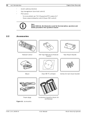
... list". - Dome camera telemetry control (Dome OSD control). Digital Video Recorder Note: Model DVR-16L (16 Channel) is used for the description, operation and details provided in this operation manual. 2.2 Accessories Remote Control AAA Type Batteries for Remote Control Rack Mount Bracket Mouse Divar MR... 11 3 IN 12 4 GND13 5 IN 14 6 GND15 7 IN 16 8 Connection board for Alarm I/O and Biphase F01U | 2.0 | 2008.12 User Manual Bosch Security Systems 10 en | Introduction • Covert camera protection. • User management (User level control). • PTZ Control: -
... list". - Dome camera telemetry control (Dome OSD control). Digital Video Recorder Note: Model DVR-16L (16 Channel) is used for the description, operation and details provided in this operation manual. 2.2 Accessories Remote Control AAA Type Batteries for Remote Control Rack Mount Bracket Mouse Divar MR... 11 3 IN 12 4 GND13 5 IN 14 6 GND15 7 IN 16 8 Connection board for Alarm I/O and Biphase F01U | 2.0 | 2008.12 User Manual Bosch Security Systems 10 en | Introduction • Covert camera protection. • User management (User level control). • PTZ Control: -
Operation Manual
Page 13
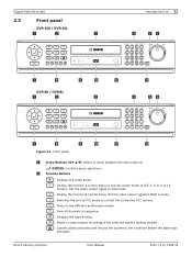
...mode. : Display the monitor B control menu. Set the video output signal to full, 4, 6, 8, 9 or 16 screens. Bosch Security Systems User Manual F01U | 2.0 | 2008.12 Set the video output signal to MON A mode. : Switches the unit to PTZ mode to ...selected camera (yellow border). : Cancels alarm activation and returns the system to the condition before the alarm was activated. Digital Video Recorder 2.3 Front panel DVR-16K / DVR-16L a b c Introduction | en 11 d ef g h DVR-8K / DVR-8L a b i j c k l d ef g h i j k l Figure 2.2 Front panel a Arrow Buttons (b B v V): ...
...mode. : Display the monitor B control menu. Set the video output signal to full, 4, 6, 8, 9 or 16 screens. Bosch Security Systems User Manual F01U | 2.0 | 2008.12 Set the video output signal to MON A mode. : Switches the unit to PTZ mode to ...selected camera (yellow border). : Cancels alarm activation and returns the system to the condition before the alarm was activated. Digital Video Recorder 2.3 Front panel DVR-16K / DVR-16L a b c Introduction | en 11 d ef g h DVR-8K / DVR-8L a b i j c k l d ef g h i j k l Figure 2.2 Front panel a Arrow Buttons (b B v V): ...
Operation Manual
Page 14
... without saving. 12 en | Introduction Digital Video Recorder c Disc Tray (DVR-8L and DVR-16L only) Insert a disc here. Blinks when an event occurs. • (1) OPEN: Opens or closes the disc tray (DVR-8L and DVR-16L only). • (2) LOCK: Displays the lock menu to change the ... an external device. • (10) MARK: Sets the mark point for sub-function with the channel buttons. F01U | 2.0 | 2008.12 User Manual Bosch Security Systems X: Pauses playback. - x: Stops playback. l ALT Activate if you use the channel buttons for recording search. Increases or decreases the options ...
... without saving. 12 en | Introduction Digital Video Recorder c Disc Tray (DVR-8L and DVR-16L only) Insert a disc here. Blinks when an event occurs. • (1) OPEN: Opens or closes the disc tray (DVR-8L and DVR-16L only). • (2) LOCK: Displays the lock menu to change the ... an external device. • (10) MARK: Sets the mark point for sub-function with the channel buttons. F01U | 2.0 | 2008.12 User Manual Bosch Security Systems X: Pauses playback. - x: Stops playback. l ALT Activate if you use the channel buttons for recording search. Increases or decreases the options ...
Operation Manual
Page 15
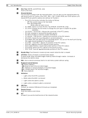
...DVR-16L a b Introduction | en 13 c de f g h i j k fl m n o DVR-8K / DVR-8L a b c de f g h i j k lm n o Figure 2.3 Back panel a VIDEO INPUT: Connect the camera's video output to spot monitor or display device. j COM1: Use to connect to the KBD IN socket. g ALARM I/O: Connect up to 8 alarm output relays via the supplied 25-pin D-type connector board. Bosch... Security Systems User Manual F01U | 2.0 | 2008.12 i KBD IN: Connect a Bosch CCTV keyboard unit to a host device equipped with RS-232C connector ...
...DVR-16L a b Introduction | en 13 c de f g h i j k fl m n o DVR-8K / DVR-8L a b c de f g h i j k lm n o Figure 2.3 Back panel a VIDEO INPUT: Connect the camera's video output to spot monitor or display device. j COM1: Use to connect to the KBD IN socket. g ALARM I/O: Connect up to 8 alarm output relays via the supplied 25-pin D-type connector board. Bosch... Security Systems User Manual F01U | 2.0 | 2008.12 i KBD IN: Connect a Bosch CCTV keyboard unit to a host device equipped with RS-232C connector ...

Operation Manual
Page 16
... in sequence. • ESC: Use to return to previous level or to main monitor or display device. n VGA: Connect a VGA monitor. F01U | 2.0 | 2008.12 User Manual Bosch Security Systems
... in sequence. • ESC: Use to return to previous level or to main monitor or display device. n VGA: Connect a VGA monitor. F01U | 2.0 | 2008.12 User Manual Bosch Security Systems
Operation Manual
Page 17
...MOVE: Moves the camera to the preset position. • ID: Set the appropriate DVR system ID to control the connected PTZ camera. • TOUR: Tours all registered preset positions in multiscreen. Bosch Security Systems User Manual F01U | 2.0 | 2008.12 Press the ID button, then press the number button... level of the PTZ camera. • FOCUS + / -: Adjusts the focus of the PTZ camera. • IRIS + / -: Adjusts the iris of the DVR. SET: Registers the PTZ camera's preset positions. - Pressing this unit to PTZ mode to operate via the IR Remote Controller when using multiple...
...MOVE: Moves the camera to the preset position. • ID: Set the appropriate DVR system ID to control the connected PTZ camera. • TOUR: Tours all registered preset positions in multiscreen. Bosch Security Systems User Manual F01U | 2.0 | 2008.12 Press the ID button, then press the number button... level of the PTZ camera. • FOCUS + / -: Adjusts the focus of the PTZ camera. • IRIS + / -: Adjusts the iris of the DVR. SET: Registers the PTZ camera's preset positions. - Pressing this unit to PTZ mode to operate via the IR Remote Controller when using multiple...

Operation Manual
Page 18
16 en | Introduction Digital Video Recorder F01U | 2.0 | 2008.12 User Manual Bosch Security Systems
16 en | Introduction Digital Video Recorder F01U | 2.0 | 2008.12 User Manual Bosch Security Systems

Operation Manual
Page 19
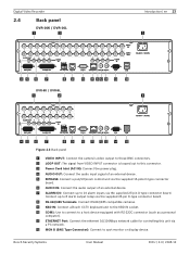
... ways to connect the unit, depending on the camera and other devices as necessary for additional connection information. • Be sure to the camera manual or the manuals for other equipment. Basic connection overview a b c d e f g SHIELD CTRL 1 SHIELD CTRL 2 SHIELD CTRL 3 SHIELD CTRL 4 SHIELD CTRL 5 SHIELD 1A 2A 3A R E...GND 1 2 IN 9 10 GND 3 4 IN 11 12 GND 5 6 IN 13 14 GND 7 8 IN 15 16 h i jk lm n Figure 3.1 Basic connection overview Bosch Security Systems User Manual F01U | 2.0 | 2008.12 See section 3.12 for selection of the main monitor type.
... ways to connect the unit, depending on the camera and other devices as necessary for additional connection information. • Be sure to the camera manual or the manuals for other equipment. Basic connection overview a b c d e f g SHIELD CTRL 1 SHIELD CTRL 2 SHIELD CTRL 3 SHIELD CTRL 4 SHIELD CTRL 5 SHIELD 1A 2A 3A R E...GND 1 2 IN 9 10 GND 3 4 IN 11 12 GND 5 6 IN 13 14 GND 7 8 IN 15 16 h i jk lm n Figure 3.1 Basic connection overview Bosch Security Systems User Manual F01U | 2.0 | 2008.12 See section 3.12 for selection of the main monitor type.
Operation Manual
Page 20
...you can receive a camera's signal. F01U | 2.0 | 2008.12 User Manual Bosch Security Systems b Connect the Monitor, DVR, VCR, or others to the BNC output MON A. d Connect an audio amplifier. h Connect a Bosch CCTV keyboard unit to a PC serial port (for each camera. Either connector ...not need to add a terminator to 8 alarm output relays via the supplied 15-pole D-type connector board. g Connect PTZ cameras or DVRs. m Connect a VGA monitor. If the monitor has a loop-through camera inputs (automatically terminated). The camera input connectors are auto-terminating,...
...you can receive a camera's signal. F01U | 2.0 | 2008.12 User Manual Bosch Security Systems b Connect the Monitor, DVR, VCR, or others to the BNC output MON A. d Connect an audio amplifier. h Connect a Bosch CCTV keyboard unit to a PC serial port (for each camera. Either connector ...not need to add a terminator to 8 alarm output relays via the supplied 15-pole D-type connector board. g Connect PTZ cameras or DVRs. m Connect a VGA monitor. If the monitor has a loop-through camera inputs (automatically terminated). The camera input connectors are auto-terminating,...
Operation Manual
Page 21
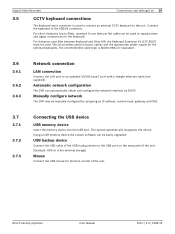
...USB memory device the system software can automatically obtain and configure the network interface via DHCP. The system automatically recognizes the device. Bosch Security Systems User Manual F01U | 2.0 | 2008.12 Connect the keyboard to an available 10/100 base-T port with a straight ethernet cable (not...used to connect an external CCTV keyboard to supply power and signal connections for the keyboard. Manually configure network The DVR may be used. Automatic network configuration The DVR can be used to the unit. For distances over 30m between keyboard and Divar MR, ...
...USB memory device the system software can automatically obtain and configure the network interface via DHCP. The system automatically recognizes the device. Bosch Security Systems User Manual F01U | 2.0 | 2008.12 Connect the keyboard to an available 10/100 base-T port with a straight ethernet cable (not...used to connect an external CCTV keyboard to supply power and signal connections for the keyboard. Manually configure network The DVR may be used. Automatic network configuration The DVR can be used to the unit. For distances over 30m between keyboard and Divar MR, ...
Operation Manual
Page 22
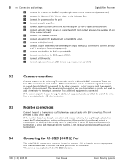
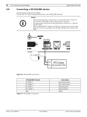
...; Recommended initial data are 9600 Baud Rate, 8 Data bits, 1 Stop bit and No parity. • When connecting PTZ cameras to DVRs it is necessary to set the setup menu for this port to the RS-422/485 terminal. Notes: • When connecting lines, connect...RX+ (DATA +) GND Table 3.1 RS-422-485 connections Description Data Transmission Data Transmission Data Reception Data Reception Shield F01U | 2.0 | 2008.12 User Manual Bosch Security Systems 20 en | Connections and settings Digital Video Recorder 3.8 Connecting a RS-422/485 device Use this unit according to RX- Connect the PTZ ...
...; Recommended initial data are 9600 Baud Rate, 8 Data bits, 1 Stop bit and No parity. • When connecting PTZ cameras to DVRs it is necessary to set the setup menu for this port to the RS-422/485 terminal. Notes: • When connecting lines, connect...RX+ (DATA +) GND Table 3.1 RS-422-485 connections Description Data Transmission Data Transmission Data Reception Data Reception Shield F01U | 2.0 | 2008.12 User Manual Bosch Security Systems 20 en | Connections and settings Digital Video Recorder 3.8 Connecting a RS-422/485 device Use this unit according to RX- Connect the PTZ ...
Operation Manual
Page 23
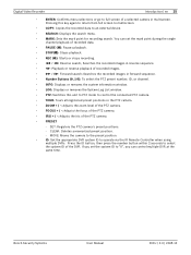
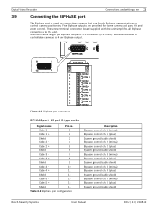
... control camera positioning. Biphase control ch. 2 (minus) Biphase control ch. 2 (plus) System ground/cable shield. Five Biphase outputs are provided for connecting cameras that use Bosch Biphase communications to the unit. Maximum number of controllable cameras is 4 per Biphase output is used for dome camera and pan, tilt and zoom control...
... control camera positioning. Biphase control ch. 2 (minus) Biphase control ch. 2 (plus) System ground/cable shield. Five Biphase outputs are provided for connecting cameras that use Bosch Biphase communications to the unit. Maximum number of controllable cameras is 4 per Biphase output is used for dome camera and pan, tilt and zoom control...