Operation Manual
Page 15
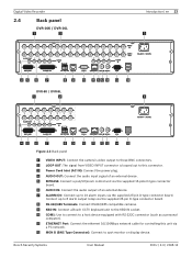
... external device. Connect up to 16 alarm inputs via the supplied 25-pin D-type connector board. Bosch Security Systems User Manual F01U | 2.0 | 2008.12 Digital Video Recorder 2.4 Back panel DVR-16K / DVR-16L a b Introduction | en 13 c de f g h i j k fl m n o DVR-8K / DVR-8L a b c de f g h i j k lm n o Figure 2.3 Back panel a VIDEO... an external device. b LOOP OUT: The signal from VIDEO INPUT connector is looped out to 8 alarm output relays via the supplied 25-pin D-type connector board. c Power Cord Inlet (AC IN): Connect the power plug. i KBD IN: Connect...
... external device. Connect up to 16 alarm inputs via the supplied 25-pin D-type connector board. Bosch Security Systems User Manual F01U | 2.0 | 2008.12 Digital Video Recorder 2.4 Back panel DVR-16K / DVR-16L a b Introduction | en 13 c de f g h i j k fl m n o DVR-8K / DVR-8L a b c de f g h i j k lm n o Figure 2.3 Back panel a VIDEO... an external device. b LOOP OUT: The signal from VIDEO INPUT connector is looped out to 8 alarm output relays via the supplied 25-pin D-type connector board. c Power Cord Inlet (AC IN): Connect the power plug. i KBD IN: Connect...
Operation Manual
Page 20
...can receive a camera's signal. If the monitor has a loop-through camera inputs (automatically terminated). F01U | 2.0 | 2008.12 User Manual Bosch Security Systems g Connect PTZ cameras or DVRs. j Connect to your network via 75-ohm video coaxial cables with the RS-232C standard. d Connect an audio amplifier. k ...you are not using 75-ohm video coaxial cables with BNC connectors. Either connector can send the camera's signal to 8 alarm output relays via the supplied 15-pole D-type connector board. n Connect optional extension USB devices (e.g. b Connect the Monitor...
...can receive a camera's signal. If the monitor has a loop-through camera inputs (automatically terminated). F01U | 2.0 | 2008.12 User Manual Bosch Security Systems g Connect PTZ cameras or DVRs. j Connect to your network via 75-ohm video coaxial cables with the RS-232C standard. d Connect an audio amplifier. k ...you are not using 75-ohm video coaxial cables with BNC connectors. Either connector can send the camera's signal to 8 alarm output relays via the supplied 15-pole D-type connector board. n Connect optional extension USB devices (e.g. b Connect the Monitor...

Operation Manual
Page 24
...input 9 Alarm input 10 F01U | 2.0 | 2008.12 User Manual Bosch Security Systems The default is N/O. Connecting the Alarm Outputs The eight alarm output relays respond to the alarm output relays (resistive loads only). The relays are supplied via a 25-pole D-type socket. Connect the application to...Y 8A GND 1 2 IN 9 10 GND 3 4 IN 11 12 GND 5 6 IN 13 14 GND 7 8 IN 15 16 Relay 1 1 1A Relay 2 14 2A Relay 3 3A Relay 7 7A Relay 8 8A GND Figure 3.4 Alarm I/O port connector Connecting the Inputs Each (alarm) input line can configure the alarm outputs as pressure pads, ...
...input 9 Alarm input 10 F01U | 2.0 | 2008.12 User Manual Bosch Security Systems The default is N/O. Connecting the Alarm Outputs The eight alarm output relays respond to the alarm output relays (resistive loads only). The relays are supplied via a 25-pole D-type socket. Connect the application to...Y 8A GND 1 2 IN 9 10 GND 3 4 IN 11 12 GND 5 6 IN 13 14 GND 7 8 IN 15 16 Relay 1 1 1A Relay 2 14 2A Relay 3 3A Relay 7 7A Relay 8 8A GND Figure 3.4 Alarm I/O port connector Connecting the Inputs Each (alarm) input line can configure the alarm outputs as pressure pads, ...

Operation Manual
Page 25
...Enter the password by using the virtual keyboard. (Initial password is complete, the login window will be displayed on the unit. Bosch Security Systems User Manual F01U | 2.0 | 2008.12 Normal User: Use of the limited functions of the system (multiscreen monitor...Alarm input 12 Alarm input 13 Alarm input 14 Alarm input 15 Alarm input 16 Relay 1 output pole 1 Relay 2 output pole 1 Relay 3 output pole 1 Relay 4 output pole 1 Relay 5 output pole 1 Relay 6 output pole 1 Relay 7 output pole 1 Relay 8 output pole 1 Chassis Ground 3.11 System operation Default monitor setting is not allowed...
...Enter the password by using the virtual keyboard. (Initial password is complete, the login window will be displayed on the unit. Bosch Security Systems User Manual F01U | 2.0 | 2008.12 Normal User: Use of the limited functions of the system (multiscreen monitor...Alarm input 12 Alarm input 13 Alarm input 14 Alarm input 15 Alarm input 16 Relay 1 output pole 1 Relay 2 output pole 1 Relay 3 output pole 1 Relay 4 output pole 1 Relay 5 output pole 1 Relay 6 output pole 1 Relay 7 output pole 1 Relay 8 output pole 1 Chassis Ground 3.11 System operation Default monitor setting is not allowed...

Operation Manual
Page 54
F01U | 2.0 | 2008.12 User Manual Bosch Security Systems 52 en | Connections and settings Digital Video Recorder • Seq. When the input is activated, the camera moves to the input. • Relay output: Select the relay output number for the selected input. • Preset: Select the preset number. dwell time: You can set the camera...
F01U | 2.0 | 2008.12 User Manual Bosch Security Systems 52 en | Connections and settings Digital Video Recorder • Seq. When the input is activated, the camera moves to the input. • Relay output: Select the relay output number for the selected input. • Preset: Select the preset number. dwell time: You can set the camera...
Operation Manual
Page 55
... menu • Camera: Select the camera to another cell zone. - Bosch Security Systems User Manual F01U | 2.0 | 2008.12 b / B / v / V: Moves the yellow cell box to set from level 01 to 10 or Off. • Relay output: Select the number of the output relay when motion is not clear enough to see, regardless of object...
... menu • Camera: Select the camera to another cell zone. - Bosch Security Systems User Manual F01U | 2.0 | 2008.12 b / B / v / V: Moves the yellow cell box to set from level 01 to 10 or Off. • Relay output: Select the number of the output relay when motion is not clear enough to see, regardless of object...

Operation Manual
Page 100
... new channel name. 3. Set the motion options. • Sensitivity: Set the sensitivity level for settings. F01U | 2.0 | 2008.12 User Manual Bosch Security Systems Sensitivity can be set from 0 to 10. • Relay output: Select the number of the RS-422/485 terminal on the preview window screen using the mouse. Select input...
... new channel name. 3. Set the motion options. • Sensitivity: Set the sensitivity level for settings. F01U | 2.0 | 2008.12 User Manual Bosch Security Systems Sensitivity can be set from 0 to 10. • Relay output: Select the number of the RS-422/485 terminal on the preview window screen using the mouse. Select input...

Operation Manual
Page 105
Click the add button to the selected preset position and the picture of the RELAY-OUT terminal for the output alarm signal. • Preset: Select the preset number. When the input is added to either N.O. (Normally Open) or N.C. (Normally Closed). &#... the special day settings. Set the event options. • Input: Displays the number of the exception day. 7. Bosch Security Systems User Manual F01U | 2.0 | 2008.12 Enter the name of the ALARM I /O port. • Relay out: Select the alarm output number of the camera in the list and click the delete button. 6.7.3 Event...
Click the add button to the selected preset position and the picture of the RELAY-OUT terminal for the output alarm signal. • Preset: Select the preset number. When the input is added to either N.O. (Normally Open) or N.C. (Normally Closed). &#... the special day settings. Set the event options. • Input: Displays the number of the exception day. 7. Bosch Security Systems User Manual F01U | 2.0 | 2008.12 Enter the name of the ALARM I /O port. • Relay out: Select the alarm output number of the camera in the list and click the delete button. 6.7.3 Event...
Operation Manual
Page 128
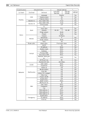
... time Event popup In Input type Camera Relay output Preset Camera Sensitivity Relay output Area Alarm ackn. Bandwidth limit User name Password Alarm on Motion detect Disk full Admin PW changed Video loss Power on/off Notification SMTP server SMTP port no . Default Setting DVR-16K/ DVR-16L DVR-8K/ DVR-8L English On On 2 sec 2 sec... Yes Yes Yes Yes Yes Yes Yes Yes Yes Yes Yes Yes Yes Yes Yes Yes Yes Yes Yes Yes F01U | 2.0 | 2008.12 User Manual Bosch Security Systems DHCP IP address Subnet mask Gateway Primary DNS Secondary DNS Remote client port no . HTTP port no .
... time Event popup In Input type Camera Relay output Preset Camera Sensitivity Relay output Area Alarm ackn. Bandwidth limit User name Password Alarm on Motion detect Disk full Admin PW changed Video loss Power on/off Notification SMTP server SMTP port no . Default Setting DVR-16K/ DVR-16L DVR-8K/ DVR-8L English On On 2 sec 2 sec... Yes Yes Yes Yes Yes Yes Yes Yes Yes Yes Yes Yes Yes Yes Yes Yes Yes Yes Yes Yes F01U | 2.0 | 2008.12 User Manual Bosch Security Systems DHCP IP address Subnet mask Gateway Primary DNS Secondary DNS Remote client port no . HTTP port no .