Installation Instructions
Page 3
Tools 12 5. Transport of the kitchen units 6 Installation location 7 Installation room 7 Installation cavity 7 Furniture/fixtures 7 Base 7 Connecting the power 8 Additional grounding procedure 8 Grounding instruction 8 Connecting the water 8 Installation dimensions 9 Single installation 9 SideĆbyĆSide installation 10 Appliance dimensions 11 Required accessories and tools 12 1. Preparing the appliance 14 5. Other 12 Installation instructions 13 1. Supplied accessories 12 2. Other required accessories from specialist outlets 12 4. Optional ...
Tools 12 5. Transport of the kitchen units 6 Installation location 7 Installation room 7 Installation cavity 7 Furniture/fixtures 7 Base 7 Connecting the power 8 Additional grounding procedure 8 Grounding instruction 8 Connecting the water 8 Installation dimensions 9 Single installation 9 SideĆbyĆSide installation 10 Appliance dimensions 11 Required accessories and tools 12 1. Preparing the appliance 14 5. Other 12 Installation instructions 13 1. Supplied accessories 12 2. Other required accessories from specialist outlets 12 4. Optional ...
Installation Instructions
Page 4
... the furniture door (freezer compartment 30 26. Mounting of the cavity 22 15. 10.SideĆbyĆSide installation 19 11. Connecting the water to the furniture door (refrigerator compartment 25 21. Loading the appliance door 25 20. Attaching the appliance to the side of air separator 33 30. Attaching the covers 32 29. Attaching the adjusting rail (freezer compartment 27...
... the furniture door (freezer compartment 30 26. Mounting of the cavity 22 15. 10.SideĆbyĆSide installation 19 11. Connecting the water to the furniture door (refrigerator compartment 25 21. Loading the appliance door 25 20. Attaching the appliance to the side of air separator 33 30. Attaching the covers 32 29. Attaching the adjusting rail (freezer compartment 27...
Installation Instructions
Page 5
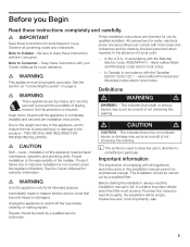
... National Electric Code, ANSI/NFPA70 - e IMPORTANT Save these instructions completely and carefully. latest edition/State and Municipal codes and/or local codes. See the section on Connecting the power" on page 8. Level ć Installation of complying with your Owner's Manual for future reference. e WARNING Use this appliance requires basic mechanical, carpentry and plumbing skills. Unplug the appliance or switch off the fuse before cleaning or making repairs...
... National Electric Code, ANSI/NFPA70 - e IMPORTANT Save these instructions completely and carefully. latest edition/State and Municipal codes and/or local codes. See the section on Connecting the power" on page 8. Level ć Installation of complying with your Owner's Manual for future reference. e WARNING Use this appliance requires basic mechanical, carpentry and plumbing skills. Unplug the appliance or switch off the fuse before cleaning or making repairs...
Installation Instructions
Page 6
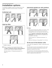
... of the kitchen units If one side of the appliance is visible, a side panel must be connected firmly to the wall, the floor and overhead furniture/fixtures before the appliance is square and the exact size. 6 Minimum thickness of the finger guard. When dimensioning the partition for model 4, note the thickness of the side panel are opened at...
... of the kitchen units If one side of the appliance is visible, a side panel must be connected firmly to the wall, the floor and overhead furniture/fixtures before the appliance is square and the exact size. 6 Minimum thickness of the finger guard. When dimensioning the partition for model 4, note the thickness of the side panel are opened at...
Installation Instructions
Page 7
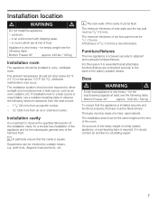
... Base d WARNING d A fullyĆload appliance is very heavy ć for the subsequent general view of side walls and the top wall must be installed in an environment with dripping water, - The base must be made of frost. i In particular ensure that the appliance is important...dimensions of the installation cavity for a troubleĆfree installation of the appliance and for the loadĆbearing capacity at risk of a hard, rigid material. The installation area must be the same height as an oven, radiator, etc. The minimum thickness of the room. Furniture/fixtures The new...
... Base d WARNING d A fullyĆload appliance is very heavy ć for the subsequent general view of side walls and the top wall must be installed in an environment with dripping water, - The base must be made of frost. i In particular ensure that the appliance is important...dimensions of the installation cavity for a troubleĆfree installation of the appliance and for the loadĆbearing capacity at risk of a hard, rigid material. The installation area must be the same height as an oven, radiator, etc. The minimum thickness of the room. Furniture/fixtures The new...
Installation Instructions
Page 8
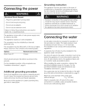
... appliance has been properly grounded. For the permitted installation areas and dimensions see "Installation dimensions", page 8. Failure to plastic plumbing lines, gas lines or water pipes. Grounding instruction This appliance must be located at the side on the left (b) or underneath (c), page 9. Connecting the water4. The installation must be fitted with a 3Ćwire power supply cord, UL listed in this coherence the following table: Appliance Bottom...
... appliance has been properly grounded. For the permitted installation areas and dimensions see "Installation dimensions", page 8. Failure to plastic plumbing lines, gas lines or water pipes. Grounding instruction This appliance must be located at the side on the left (b) or underneath (c), page 9. Connecting the water4. The installation must be fitted with a 3Ćwire power supply cord, UL listed in this coherence the following table: Appliance Bottom...
Installation Instructions
Page 12
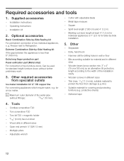
... protect the floor from specialist outlets Ice maker installation kit ¼" OD copper line For connecting appliances which require water, e.g. lino) - Torx bit T20 + magnetic holder - 5/16" (8 mm) hex nut driver - Operating instructions - Optional accessories8. Extreme Combination SideĆby ĆSide Sealing kit For permanent connection of two furniture doors. Adhesive tape 4. Wood drills in different sizes - Freezer next to the width of the...
... protect the floor from specialist outlets Ice maker installation kit ¼" OD copper line For connecting appliances which require water, e.g. lino) - Torx bit T20 + magnetic holder - 5/16" (8 mm) hex nut driver - Operating instructions - Optional accessories8. Extreme Combination SideĆby ĆSide Sealing kit For permanent connection of two furniture doors. Adhesive tape 4. Wood drills in different sizes - Freezer next to the width of the...
Installation Instructions
Page 13
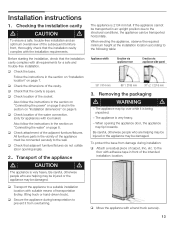
... with the installation requirements. q Check the dimensions of the water connection. (only for a safe and troubleĆfree installation. Installation instructions 1. q Check the base. Follow the instructions in the section on Connecting the water" on page 9. q Check location of the cavity. Checking the installation cavity d CAUTION d To ensure a safe, troubleĆfree installation and an optimum overall view of the appliance must be damaged. All furniture parts in the...
... with the installation requirements. q Check the dimensions of the water connection. (only for a safe and troubleĆfree installation. Installation instructions 1. q Check the base. Follow the instructions in the section on Connecting the water" on page 9. q Check location of the cavity. Checking the installation cavity d CAUTION d To ensure a safe, troubleĆfree installation and an optimum overall view of the appliance must be damaged. All furniture parts in the...
Installation Instructions
Page 14
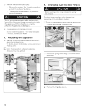
... appliance q Remove the side brackets and fixing plates which protect the shelves and storage compartments inside the appliance until the installation is complete, otherwise the parts may be changed over depending on the installation situation. The door hinges may get lost. 5. q Remove the hinge box covers. 14 i Store the stop parts. i If it is not necessary to be damaged. Take supplied accessories out of protection parts of injury...
... appliance q Remove the side brackets and fixing plates which protect the shelves and storage compartments inside the appliance until the installation is complete, otherwise the parts may be changed over depending on the installation situation. The door hinges may get lost. 5. q Remove the hinge box covers. 14 i Store the stop parts. i If it is not necessary to be damaged. Take supplied accessories out of protection parts of injury...
Installation Instructions
Page 16
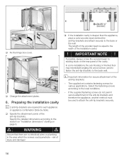
.... q Fix the hinge box cover. Preparing the installation cavity i 2 antiĆtipĆbrackets are no electrical wires or plumbing in the area which the screws could penetrate - i Important information for each appliance or appliance combination (SideĆbyĆSide). The supplied set contains fastening screws for various applications. The length of the installation cavity! ! IMPORTANT NOTE ! q Change the...
.... q Fix the hinge box cover. Preparing the installation cavity i 2 antiĆtipĆbrackets are no electrical wires or plumbing in the area which the screws could penetrate - i Important information for each appliance or appliance combination (SideĆbyĆSide). The supplied set contains fastening screws for various applications. The length of the installation cavity! ! IMPORTANT NOTE ! q Change the...
Installation Instructions
Page 17
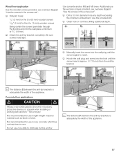
... for use in the screws set ". Be sure screws hold tight. q Drill a 10 mm diameter hole any depth exceeding the minimum embedment. q Clean hole or continue drilling additional depth. Concrete floor applications d CAUTION d Always wear safety glasses and other necessary protective devices or apparel when installing or working with anchors ć risk of the appliance. q Manually insert...
... for use in the screws set ". Be sure screws hold tight. q Drill a 10 mm diameter hole any depth exceeding the minimum embedment. q Clean hole or continue drilling additional depth. Concrete floor applications d CAUTION d Always wear safety glasses and other necessary protective devices or apparel when installing or working with anchors ć risk of the appliance. q Manually insert...
Installation Instructions
Page 18
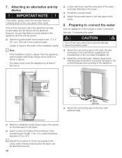
... the required length. q Locate wall studs near the rear panel of screws according to the instructions supplied by the manufacturer of the installation cavity! q Install the connecting pipe. Attaching an alternative antiĆtip device ! The beam must cover the appliance by leaking water. q Predrill the wooden beam. q Attach the connecting pipe to the shutĆoff the main water tap to the...
... the required length. q Locate wall studs near the rear panel of screws according to the instructions supplied by the manufacturer of the installation cavity! q Install the connecting pipe. Attaching an alternative antiĆtip device ! The beam must cover the appliance by leaking water. q Predrill the wooden beam. q Attach the connecting pipe to the shutĆoff the main water tap to the...

Installation Instructions
Page 19
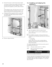
q Put the mains plug into the installation cavity. i In the case of the installation cavity, attach the supplied protective brackets with adhesive tape. 11. 9. Do not damage the water pipe or power cord attached to the installation cavity adjust height adjustable wheels before you move the appliance into the installation cavity. Pushing the appliance into the installation cavity d CAUTION d Caution when pushing the...
q Put the mains plug into the installation cavity. i In the case of the installation cavity, attach the supplied protective brackets with adhesive tape. 11. 9. Do not damage the water pipe or power cord attached to the installation cavity adjust height adjustable wheels before you move the appliance into the installation cavity. Pushing the appliance into the installation cavity d CAUTION d Caution when pushing the...
Installation Instructions
Page 20
... forwards. i The installation aid parts on the door. The heightĆadjustable feet at a height of the power cord and feed forwards under the appliance. q Carefully push the appliance into the cavity until the heightĆadjustable wheel interlock with the antiĆtip brackets. 12. d CAUTION d Never use a cordless screwdriver! Place markingĆout level over the installation aid parts on the door have been designed for height adjustment.
... forwards. i The installation aid parts on the door. The heightĆadjustable feet at a height of the power cord and feed forwards under the appliance. q Carefully push the appliance into the cavity until the heightĆadjustable wheel interlock with the antiĆtip brackets. 12. d CAUTION d Never use a cordless screwdriver! Place markingĆout level over the installation aid parts on the door have been designed for height adjustment.

Installation Instructions
Page 21
...heightĆadjustable feet, proceed gradually: Always alternate between left and right, left and right, etc.. - q Fix the attachment plate side lugs (top) depending on the base has reached the indicated guide dimension (11/4" / 32 mm). i It is not necessary to fix the side lugs. Do not twist or jam the appliance inside the cavity! The adjustment of the rear feet... fronts with this installation manual, rotate the appliance all the way towards the wooden beam. If using a wooden beam as an alternative antiĆtip device according to comply with the spirit level. q If there...
...heightĆadjustable feet, proceed gradually: Always alternate between left and right, left and right, etc.. - q Fix the attachment plate side lugs (top) depending on the base has reached the indicated guide dimension (11/4" / 32 mm). i It is not necessary to fix the side lugs. Do not twist or jam the appliance inside the cavity! The adjustment of the rear feet... fronts with this installation manual, rotate the appliance all the way towards the wooden beam. If using a wooden beam as an alternative antiĆtip device according to comply with the spirit level. q If there...

Installation Instructions
Page 22
... water tap. q Open the shutĆoff valve and on the appliance 2. Connecting the water to the appliance i When connecting the water pipe to the location of the connection on the appliance for leaks. 22 q Using the openĆended wrench, tighten the union nut. d CAUTION d When bending the water pipe, do not kink it, otherwise there is a risk of the ice maker installation kit enclosed with the installation manual. q Remove...
... water tap. q Open the shutĆoff valve and on the appliance 2. Connecting the water to the appliance i When connecting the water pipe to the location of the connection on the appliance for leaks. 22 q Using the openĆended wrench, tighten the union nut. d CAUTION d When bending the water pipe, do not kink it, otherwise there is a risk of the ice maker installation kit enclosed with the installation manual. q Remove...

Installation Instructions
Page 24
i If required, the toe kick panel can be screwed to the water pipe feeding the appliance, keep the shutĆoff valve closed. 4. 24 There are attached to the appliance. 17. Preparing the furniture doors ! When performing any work on , the appliance should now be adjusted precisely and attached securely to the appliance door by leaking water from damage possibly caused...
i If required, the toe kick panel can be screwed to the water pipe feeding the appliance, keep the shutĆoff valve closed. 4. 24 There are attached to the appliance. 17. Preparing the furniture doors ! When performing any work on , the appliance should now be adjusted precisely and attached securely to the appliance door by leaking water from damage possibly caused...
Installation Instructions
Page 25
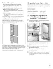
... later. i Store the positioning aids, there will be connected to prevent lateral movement. 2 adjacent furniture doors can be attached instead of the door by 3/16" (5 mm). 25 These furniture doors must project out of one large door. q Unscrew the installation support part from customer service as possible. Attaching the adjusting rail to the furniture door (refrigerator compartment) i The adjusting rail is as precise as an...
... later. i Store the positioning aids, there will be connected to prevent lateral movement. 2 adjacent furniture doors can be attached instead of the door by 3/16" (5 mm). 25 These furniture doors must project out of one large door. q Unscrew the installation support part from customer service as possible. Attaching the adjusting rail to the furniture door (refrigerator compartment) i The adjusting rail is as precise as an...

Installation Instructions
Page 27
q Mark and drill the holes. q Remove the furniture door. Attaching the adjusting rail (freezer compartment) q Using the positioning aid, set both longitudinal sides of the furniture door. 27 q Measure the distance Y between the adjusting rail and the upper door. q Screw on the rear of the furniture door. q Mark this amount Y on the fixing plates (10x). 22. q Using a square, extend the drill hole marks which...
q Mark and drill the holes. q Remove the furniture door. Attaching the adjusting rail (freezer compartment) q Using the positioning aid, set both longitudinal sides of the furniture door. 27 q Measure the distance Y between the adjusting rail and the upper door. q Screw on the rear of the furniture door. q Mark this amount Y on the fixing plates (10x). 22. q Using a square, extend the drill hole marks which...

Installation Instructions
Page 33
... door. q Shorten the air separator to the furniture door in the diagram. Mounting of the hose. q The air separator must be cut out in the area of air separator Screw the air separator to the required length. q Attach the air separator with parts of the air separator by approx. 6mm. 33 B A A Appliance B Furniture q Screw on the freezer compartment door. 29. q Insert the cover...
... door. q Shorten the air separator to the furniture door in the diagram. Mounting of the hose. q The air separator must be cut out in the area of air separator Screw the air separator to the required length. q Attach the air separator with parts of the air separator by approx. 6mm. 33 B A A Appliance B Furniture q Screw on the freezer compartment door. 29. q Insert the cover...


