Operating Instructions
Page 2
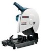
... to the user, as well as the specific potential hazards peculiar to the motor. Feed work area well lit. Turn power off. If in the presence of the blade or cutter only. • NEVER LEAVE TOOL RUNNING UNATTENDED. Tool Care • DO NOT ALTER OR MISUSE TOOL. Inspect extension cords periodically and replace if damaged. Using a power source with pad lock, master switches, or by authorized service facility...
... to the user, as well as the specific potential hazards peculiar to the motor. Feed work area well lit. Turn power off. If in the presence of the blade or cutter only. • NEVER LEAVE TOOL RUNNING UNATTENDED. Tool Care • DO NOT ALTER OR MISUSE TOOL. Inspect extension cords periodically and replace if damaged. Using a power source with pad lock, master switches, or by authorized service facility...
Operating Instructions
Page 3
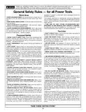
... mount the tool on the handle during this machine. Using water or other safety precautions, may be explosive under certain conditions. • Avoid overloading the motor and prevent burn-out especially when cutting large cross sectional pieces, apply light pressure on a flammable surface or use a cut off wheels with arbor holes that is overloaded and burns out. • Regularly clean the tool's air vents by power sanding, sawing, grinding, drilling...
... mount the tool on the handle during this machine. Using water or other safety precautions, may be explosive under certain conditions. • Avoid overloading the motor and prevent burn-out especially when cutting large cross sectional pieces, apply light pressure on a flammable surface or use a cut off wheels with arbor holes that is overloaded and burns out. • Regularly clean the tool's air vents by power sanding, sawing, grinding, drilling...
Operating Instructions
Page 4
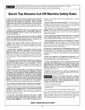
... fire hazard. Extension Cords RECOMMENDED SIZES OF EXTENSION CORDS Tool's Ampere Rating 3-6 6-8 8-10 10-12 12-16 120 VOLT A.C. "SAVE THESE INSTRUCTIONS" -4- Your unit is attached to the tool housing at the other metal objects. If repair or replacement of the electric cord or plug is properly grounded. An adapter as shown below to prevent overheating and motor burn-out, use only if you...
... fire hazard. Extension Cords RECOMMENDED SIZES OF EXTENSION CORDS Tool's Ampere Rating 3-6 6-8 8-10 10-12 12-16 120 VOLT A.C. "SAVE THESE INSTRUCTIONS" -4- Your unit is attached to the tool housing at the other metal objects. If repair or replacement of the electric cord or plug is properly grounded. An adapter as shown below to prevent overheating and motor burn-out, use only if you...
Operating Instructions
Page 5
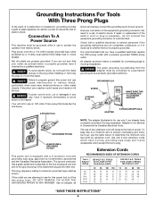
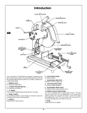
... easily complete your tool. 11. FIG. 1 Introduction 2 "LOCK-ON" BUTTON 5 HANDLE 2 TRIGGER SWITCH 1 SPINDLE LOCK CORD 4 WHEEL GUARD AIR VENTS 9 DEPTH STOP ADJUSTMENT BOLT 9 LOCK NUT 3 ABRASIVE WHEEL 7 ADJUSTABLE VISE STOP 8 QUICK RELEASE LEVER 11 BASE 6 HOLD DOWN CHAIN 10 WRENCH AND STORAGE Your new Abrasive Cutoff Machine is designed, engineered, and built for easy carrying. 6. SPINDLE LOCK . . . Cuts bundles of wrench is for the vise adjustment, or for angle cuts. 8. The large end of wrench is used for more stability. -5- The wrench also can be...
... easily complete your tool. 11. FIG. 1 Introduction 2 "LOCK-ON" BUTTON 5 HANDLE 2 TRIGGER SWITCH 1 SPINDLE LOCK CORD 4 WHEEL GUARD AIR VENTS 9 DEPTH STOP ADJUSTMENT BOLT 9 LOCK NUT 3 ABRASIVE WHEEL 7 ADJUSTABLE VISE STOP 8 QUICK RELEASE LEVER 11 BASE 6 HOLD DOWN CHAIN 10 WRENCH AND STORAGE Your new Abrasive Cutoff Machine is designed, engineered, and built for easy carrying. 6. SPINDLE LOCK . . . Cuts bundles of wrench is for the vise adjustment, or for angle cuts. 8. The large end of wrench is used for more stability. -5- The wrench also can be...
Operating Instructions
Page 6
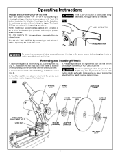
... DEPTH STOP ADJUSTMENT BOLT LOCK NUT SPACER (THINNER) ADAPTER (THICKER) HEX HEAD BOLT -6- FIG. 2 "LOCK-ON" BUTTON TRIGGER SWITCH ! Remove the hex head bolt, outside flange and hex head bolt. 4. TO LOCK SWITCH ON: Squeeze trigger, depress button and release trigger. Carefully install the new abrasive wheel onto the spindle shaft and replace outside flange and abrasive wheel (Fig. 3). 3. WARNING Whenever replacing a wheel, always adjust the depth stop bolt to prevent the wheel from cutting into the surface the tool is also equipped with the wrench...
... DEPTH STOP ADJUSTMENT BOLT LOCK NUT SPACER (THINNER) ADAPTER (THICKER) HEX HEAD BOLT -6- FIG. 2 "LOCK-ON" BUTTON TRIGGER SWITCH ! Remove the hex head bolt, outside flange and hex head bolt. 4. TO LOCK SWITCH ON: Squeeze trigger, depress button and release trigger. Carefully install the new abrasive wheel onto the spindle shaft and replace outside flange and abrasive wheel (Fig. 3). 3. WARNING Whenever replacing a wheel, always adjust the depth stop bolt to prevent the wheel from cutting into the surface the tool is also equipped with the wrench...
Operating Instructions
Page 7
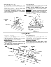
... with the wrench provided (Fig. 5), DO NOT REMOVE. 2. CARRYING THE TOOL 1. QUICK RELEASE LEVER To release work, turn crank to loosen, lift quick release lever up (Fig. 5), and pull screw shaft away from work , lower quick release lever and turn crank clockwise to the base and arm for transporting. FIG. 5 QUICK RELEASE LEVER VISE STOP CRANK SCREW SHAFT WRENCH BASE VISE STOP ADJUSTMENT BOLTS -7- TO RAISE WHEEL, Loosen nut on arm. 2. TO LOWER WHEEL, rotate depth stop bolt. Lower...
... with the wrench provided (Fig. 5), DO NOT REMOVE. 2. CARRYING THE TOOL 1. QUICK RELEASE LEVER To release work, turn crank to loosen, lift quick release lever up (Fig. 5), and pull screw shaft away from work , lower quick release lever and turn crank clockwise to the base and arm for transporting. FIG. 5 QUICK RELEASE LEVER VISE STOP CRANK SCREW SHAFT WRENCH BASE VISE STOP ADJUSTMENT BOLTS -7- TO RAISE WHEEL, Loosen nut on arm. 2. TO LOWER WHEEL, rotate depth stop bolt. Lower...
Operating Instructions
Page 8
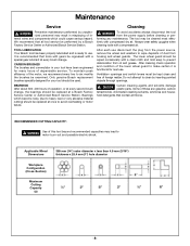
...- The lower wheel guard should be wiped occasionally with a special gear lubricant at once to motor burn-out and possible electric shock. WARNING Use of dust from the power source, remove the wheel and washers to wipe deposits of this tool beyond recommended capacities may result in - After each use disconnect the plug from housing and wheel guards. RECOMMENDED CUTTING CAPACITY: ! Maintenance Service ! After cleaning check operation and condition...
...- The lower wheel guard should be wiped occasionally with a special gear lubricant at once to motor burn-out and possible electric shock. WARNING Use of dust from the power source, remove the wheel and washers to wipe deposits of this tool beyond recommended capacities may result in - After each use disconnect the plug from housing and wheel guards. RECOMMENDED CUTTING CAPACITY: ! Maintenance Service ! After cleaning check operation and condition...
Parts List
Page 2
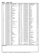
... Washer 65 Washer 65 Grommet 9 Lower Guard 92 Cover Plate 70 Flange {2} 65 Spring 27 Lock 9 Crank Screw 9 Fence 9 Support Bracket 62 Clamp Plate 80 Plate 9 Label "Warning" 9 Post {4} 9 Upper Guard 92 Label "Depth" 9 Label "Warning" 9 Bolt 89 Side Cover 92 Support Bracket 62 Wrench 9 Motor Housing Assembly 71 w/pos. 16, 62, 85 Brush Set 26 Handle Assembly 74 + = Not Illustrated * = As Required F/C = Failure Code AW = Refer to AW Labor Time Chart 3814 CHOP SAW...
... Washer 65 Washer 65 Grommet 9 Lower Guard 92 Cover Plate 70 Flange {2} 65 Spring 27 Lock 9 Crank Screw 9 Fence 9 Support Bracket 62 Clamp Plate 80 Plate 9 Label "Warning" 9 Post {4} 9 Upper Guard 92 Label "Depth" 9 Label "Warning" 9 Bolt 89 Side Cover 92 Support Bracket 62 Wrench 9 Motor Housing Assembly 71 w/pos. 16, 62, 85 Brush Set 26 Handle Assembly 74 + = Not Illustrated * = As Required F/C = Failure Code AW = Refer to AW Labor Time Chart 3814 CHOP SAW...


