
Operating Instructions
Page 3
...is contacted. Use only accessories that may become hazardous when used on another tool. Service or maintenance performed by the manufacturer for Planers Secure the material being planed. Certain cleaning agents such as possible injury. -3- Safety Rules for your application. After changing blades...to bind causing loss of children and other condition that the trigger lock is designed. Accessories that are hidden from the power source before blade is dangerous and must be misplaced or pinched, safety guard return springs may damage plastic parts. For ...
...is contacted. Use only accessories that may become hazardous when used on another tool. Service or maintenance performed by the manufacturer for Planers Secure the material being planed. Certain cleaning agents such as possible injury. -3- Safety Rules for your application. After changing blades...to bind causing loss of children and other condition that the trigger lock is designed. Accessories that are hidden from the power source before blade is dangerous and must be misplaced or pinched, safety guard return springs may damage plastic parts. For ...
Operating Instructions
Page 6
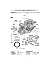
Planer FIG. 1 DEPTH ADJUSTMENT KNOB "LOCK-OFF" RELEASE BUTTON CHIP EXHAUST PORT WING KNOB TRIGGER SWITCH RABBETING DEPTH STOP (OPTIONAL) FRONT SHOE CHAMFER V-GROOVES DEPTH SCALE ...,500/min Maximum Capacities Planing depth 0 - 3/32" (0 - 2.6mm) Rabbeting depth 0 - 5/16" (0 - 9mm) Planing width 3-1/4" (82mm) -6- Functional Description and Specifications ! WARNING Disconnect the plug from the power source before making any assembly, adjustments or changing accessories. Such preventive safety measures reduce the risk of starting the tool accidentally.
Planer FIG. 1 DEPTH ADJUSTMENT KNOB "LOCK-OFF" RELEASE BUTTON CHIP EXHAUST PORT WING KNOB TRIGGER SWITCH RABBETING DEPTH STOP (OPTIONAL) FRONT SHOE CHAMFER V-GROOVES DEPTH SCALE ...,500/min Maximum Capacities Planing depth 0 - 3/32" (0 - 2.6mm) Rabbeting depth 0 - 5/16" (0 - 9mm) Planing width 3-1/4" (82mm) -6- Functional Description and Specifications ! WARNING Disconnect the plug from the power source before making any assembly, adjustments or changing accessories. Such preventive safety measures reduce the risk of starting the tool accidentally.
Operating Instructions
Page 7
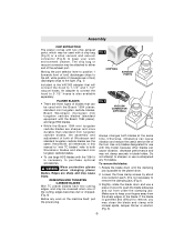
... with a chip bag (Fig.2) or a shop vacuum and vacuum connector (Fig.3) to keep your work on the machine itself, pull the power plug. Loosen the three clamp screws by about one of the cutting edges becomes dull or chipped. (Fig. 6) Before any TC blades. ... be used with the 1594 it is necessary to purchase optional accessories. ! standard mini tungsten carbide blades, Bosch Woodrazor micrograin mini tungsten carbide blades (standard equipment with the Bosch 1594 planer; Moving the port selector lever to position 1 (towards front of tool) discharges chips to the left, while...
... with a chip bag (Fig.2) or a shop vacuum and vacuum connector (Fig.3) to keep your work on the machine itself, pull the power plug. Loosen the three clamp screws by about one of the cutting edges becomes dull or chipped. (Fig. 6) Before any TC blades. ... be used with the 1594 it is necessary to purchase optional accessories. ! standard mini tungsten carbide blades, Bosch Woodrazor micrograin mini tungsten carbide blades (standard equipment with the Bosch 1594 planer; Moving the port selector lever to position 1 (towards front of tool) discharges chips to the left, while...
Operating Instructions
Page 8
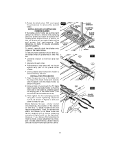
.... Under normal circumstances, the position of the blade with mineral spirits; lacquer thinner or alcohol, as shown in Figure 4, and your planer is ready for use. Using a block of wood push the TC blade back towards the blade holder so that adjustments must be disturbed... PROCEDURE 1. Blade Retainer Screws - 4. However, if you believe that the inner side of the blade is best performed by a Bosch Factory Service or Bosch Authorized Service Center. INSTALLING AND ADJUSTING MINI CARBIDE BLADES If the blades and/or holder are level.) 3. Rotate the blade drum 180...
.... Under normal circumstances, the position of the blade with mineral spirits; lacquer thinner or alcohol, as shown in Figure 4, and your planer is ready for use. Using a block of wood push the TC blade back towards the blade holder so that adjustments must be disturbed... PROCEDURE 1. Blade Retainer Screws - 4. However, if you believe that the inner side of the blade is best performed by a Bosch Factory Service or Bosch Authorized Service Center. INSTALLING AND ADJUSTING MINI CARBIDE BLADES If the blades and/or holder are level.) 3. Rotate the blade drum 180...

Operating Instructions
Page 9
... Additional pairs of the blade drum. Loosen and remove the three clamp screws with mineral spirits; CONVERSION TO HIGH-SPEED STEEL BLADES The 1594 Planer can also be purchased separately. INSTALLATION OF HSS BLADES AND RETAINERS Before inserting a new or sharpened blade, clean all surfaces (blades, retainer ... Loosen the three clamp screws completely and remove the screws and clamping jaw. 3. If the blade is gummed and difficult to the planer shoe. 2. lacquer thinner or alcohol, as this will not touch against any part of the blade. The retainer must be converted to...
... Additional pairs of the blade drum. Loosen and remove the three clamp screws with mineral spirits; CONVERSION TO HIGH-SPEED STEEL BLADES The 1594 Planer can also be purchased separately. INSTALLATION OF HSS BLADES AND RETAINERS Before inserting a new or sharpened blade, clean all surfaces (blades, retainer ... Loosen the three clamp screws completely and remove the screws and clamping jaw. 3. If the blade is gummed and difficult to the planer shoe. 2. lacquer thinner or alcohol, as this will not touch against any part of the blade. The retainer must be converted to...
Operating Instructions
Page 11
... "OFF": release the trigger switch and it will return to obtain a good surface finish. With practice and experience, it will become second nature. With the planer fully adjusted, place the front shoe on the motor, the depth setting can cause the tool to a shallow setting for the final pass to the... to the end of cut while planing.) When near the desired depth, and then re-adjust to the tool if the motor labors. Feed the planer at a uniform and reasonable rate that the workpiece is from the motor can be increased before the next cut. (Do not change depth of the...
... "OFF": release the trigger switch and it will return to obtain a good surface finish. With practice and experience, it will become second nature. With the planer fully adjusted, place the front shoe on the motor, the depth setting can cause the tool to a shallow setting for the final pass to the... to the end of cut while planing.) When near the desired depth, and then re-adjust to the tool if the motor labors. Feed the planer at a uniform and reasonable rate that the workpiece is from the motor can be increased before the next cut. (Do not change depth of the...
Operating Instructions
Page 12
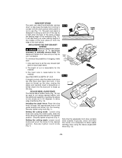
... blades are hidden from view and you may be used to allow edge chamfering (Fig. 13). The depth of the work piece (in from power source if it itself when the back of the plane crosses the leading edge of a workpiece to cut various desired widths, with the work surface...width fence (Fig. 13). -12- WARNING Remove plug from the edge of cut if contacted. If this does not break up the clog, unplug the planer and carefully insert a screwdriver or similar object into the housing. Securely tighten wing knob (Fig. 1). Setting the cutting angle: Loosen round knobs and pivot...
... blades are hidden from view and you may be used to allow edge chamfering (Fig. 13). The depth of the work piece (in from power source if it itself when the back of the plane crosses the leading edge of a workpiece to cut various desired widths, with the work surface...width fence (Fig. 13). -12- WARNING Remove plug from the edge of cut if contacted. If this does not break up the clog, unplug the planer and carefully insert a screwdriver or similar object into the housing. Securely tighten wing knob (Fig. 1). Setting the cutting angle: Loosen round knobs and pivot...
Parts Diagram
Page 2
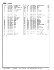
1594 PLANER Pos. 2 3 4 5/1 6 7 8 9 11 15 16 17 19 20 26 28 29 30 31 32 33 35 37 38 40 41 43 Part Number 2 604 220 479 2 ...
1594 PLANER Pos. 2 3 4 5/1 6 7 8 9 11 15 16 17 19 20 26 28 29 30 31 32 33 35 37 38 40 41 43 Part Number 2 604 220 479 2 ...

