Operating Instructions
Page 2
... electric shock. Do not abuse the cord. Refer to install a polarized outlet. Keep handles dry, clean and free from an outlet. Carrying tools with a polarized plug (one blade is grounded. Dust mask, non-skid safety shoes, hard hat, or hearing protection must be used for ...appropriate conditions. Electrical Safety Double Insulated tools are equipped with your tool. Double Insulation eliminates the need for outdoor use the cord to lose control. Avoid body contact with a DC power supply....
... electric shock. Do not abuse the cord. Refer to install a polarized outlet. Keep handles dry, clean and free from an outlet. Carrying tools with a polarized plug (one blade is grounded. Dust mask, non-skid safety shoes, hard hat, or hearing protection must be used for ...appropriate conditions. Electrical Safety Double Insulated tools are equipped with your tool. Double Insulation eliminates the need for outdoor use the cord to lose control. Avoid body contact with a DC power supply....
Operating Instructions
Page 3
... of unauthorized parts or failure to the tool and positioned for your application. Remove bad wheels immediately. Disconnect the plug from a wheel that are caused by the manufacturer for chips and cracks. Angle Grinder Safety Rules Always use tool if switch does not turn it is ...dangerous and must always be repaired. Fragments from the power source before using a grinder or installing a new wheel, inspect the grinding wheel for your...
... of unauthorized parts or failure to the tool and positioned for your application. Remove bad wheels immediately. Disconnect the plug from a wheel that are caused by the manufacturer for chips and cracks. Angle Grinder Safety Rules Always use tool if switch does not turn it is ...dangerous and must always be repaired. Fragments from the power source before using a grinder or installing a new wheel, inspect the grinding wheel for your...
Operating Instructions
Page 4
...Sparks from you or bystanders. The grinding wheel guard cannot be used for most sanding operations or for the high speed of a small angle sander/grinder, these brushes and may contain carcinogens, use special precautions. Work area should be kept out until work with these wheels may easily... bouncing and snagging the wheel, especially when working corners, sharp edges etc. Do not wrap the cord around your tool, or worn down damaged wheels from larger grinders. Do not grind or sand near flammable materials. The guard must be attached to filter out microscopic particles. -4- ...
...Sparks from you or bystanders. The grinding wheel guard cannot be used for most sanding operations or for the high speed of a small angle sander/grinder, these brushes and may contain carcinogens, use special precautions. Work area should be kept out until work with these wheels may easily... bouncing and snagging the wheel, especially when working corners, sharp edges etc. Do not wrap the cord around your tool, or worn down damaged wheels from larger grinders. Do not grind or sand near flammable materials. The guard must be attached to filter out microscopic particles. -4- ...
Operating Instructions
Page 5
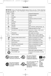
...kg Kilograms Weight min Minutes Time s Seconds Time Diameter Size of the following symbols may be used on your tool. This symbol designates that this tool is listed by Underwriters Laboratories, and listed to warning messages Ni-Cad RBRC seal Designates Ni-Cad battery recycling ...program This symbol designates that this tool is increasing from 0 setting Action in the direction of arrow Type or a characteristic of current Type or a characteristic of current...
...kg Kilograms Weight min Minutes Time s Seconds Time Diameter Size of the following symbols may be used on your tool. This symbol designates that this tool is listed by Underwriters Laboratories, and listed to warning messages Ni-Cad RBRC seal Designates Ni-Cad battery recycling ...program This symbol designates that this tool is increasing from 0 setting Action in the direction of arrow Type or a characteristic of current Type or a characteristic of current...
Operating Instructions
Page 6
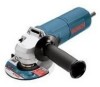
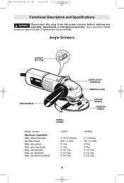
... Max. Angle Grinders SWITCH BUTTON SIDE HANDLE VENTILATION OPENINGS SPINDLE LOCK COLLAR SCREW GRINDING WHEEL WHEEL GUARD Model number Maximum Capacities Max. wire wheel Max. dry diamond wheel 1347A 4 ...1/2" (115mm) 5/8"-11 UNC 4" Dia. 3" Dia. 4 1/2" Dia. 4 1/2" Dia. 4 1/2" Dia. 1348AE 5" (127mm) 5/8"-11 UNC 4" Dia. 3" Dia. 4 1/2" Dia. 4 1/2" Dia. 4 1/2" Dia. -6- wire cup brush Max. wheel diameter Spindle thread Max. BM F000622188 12-04 12/10/04 9:27 PM Page 6 Functional Description and Specifications ! Such preventive safety measures reduce the risk of starting the tool...
... Max. Angle Grinders SWITCH BUTTON SIDE HANDLE VENTILATION OPENINGS SPINDLE LOCK COLLAR SCREW GRINDING WHEEL WHEEL GUARD Model number Maximum Capacities Max. wire wheel Max. dry diamond wheel 1347A 4 ...1/2" (115mm) 5/8"-11 UNC 4" Dia. 3" Dia. 4 1/2" Dia. 4 1/2" Dia. 4 1/2" Dia. 1348AE 5" (127mm) 5/8"-11 UNC 4" Dia. 3" Dia. 4 1/2" Dia. 4 1/2" Dia. 4 1/2" Dia. -6- wire cup brush Max. wheel diameter Spindle thread Max. BM F000622188 12-04 12/10/04 9:27 PM Page 6 Functional Description and Specifications ! Such preventive safety measures reduce the risk of starting the tool...
Operating Instructions
Page 7
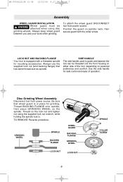
...GRINDING WHEEL SPINDLE BACKING FLANGE WHEEL GUARD BACKING FLANGE GRINDING WHEEL LOCK NUT LOCK NUT -7- SPINDLE COLLAR SCREW To attach the wheel guard DISCONNECT tool from power source. BM F000622188 12-04 12/10/04 9:27 PM Page 7 Assembly WHEEL GUARD INSTALLATION ! WARNING Wheel guard must be... threaded into the front housing on either side of operation. LOCK NUT AND BACKING FLANGE Your tool is in . Always use the supplied lock nut (and backing flange) that wheel guard is equipped with the collar screw. Always keep ...
...GRINDING WHEEL SPINDLE BACKING FLANGE WHEEL GUARD BACKING FLANGE GRINDING WHEEL LOCK NUT LOCK NUT -7- SPINDLE COLLAR SCREW To attach the wheel guard DISCONNECT tool from power source. BM F000622188 12-04 12/10/04 9:27 PM Page 7 Assembly WHEEL GUARD INSTALLATION ! WARNING Wheel guard must be... threaded into the front housing on either side of operation. LOCK NUT AND BACKING FLANGE Your tool is in . Always use the supplied lock nut (and backing flange) that wheel guard is equipped with the collar screw. Always keep ...
Operating Instructions
Page 8
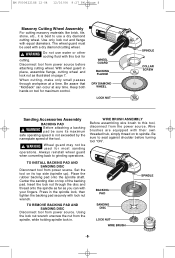
... WIRE BRUSH ASSEMBLY Before assembling wire brush to grinding operations. TO REMOVE BACKING PAD AND SANDING DISC Disconnect tool from the power source. When cutting, make only small passes through the disc and thread onto the spindle as far as illustrated on to spindle. TO INSTALL BACKING... PAD AND SANDING DISC Disconnect tool from power source. Wire brushes are equipped with your fingers. Press in place, ...
... WIRE BRUSH ASSEMBLY Before assembling wire brush to grinding operations. TO REMOVE BACKING PAD AND SANDING DISC Disconnect tool from the power source. When cutting, make only small passes through the disc and thread onto the spindle as far as illustrated on to spindle. TO INSTALL BACKING... PAD AND SANDING DISC Disconnect tool from power source. Wire brushes are equipped with your fingers. Press in place, ...
Operating Instructions
Page 9
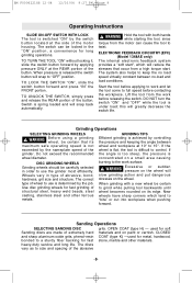
...the switch. WARNING Before using a grinding wheel, be carefully selected in order to use the grinder most efficiently. Wheels vary in the "ON" position, a convenience for fast stone, marble and...can be certain to twist. The correct type of the abrasive -9- If the angle is too steep, the pressure is concentrated on its maximum safe operating speed is ... exceed the recommended wheel diameter. The switch can cause the tool to grind while pulling tool backwards until wheel becomes rounded on a small area causing burning to control. this will snap back automatically....
...the switch. WARNING Before using a grinding wheel, be carefully selected in order to use the grinder most efficiently. Wheels vary in the "ON" position, a convenience for fast stone, marble and...can be certain to twist. The correct type of the abrasive -9- If the angle is too steep, the pressure is concentrated on its maximum safe operating speed is ... exceed the recommended wheel diameter. The switch can cause the tool to grind while pulling tool backwards until wheel becomes rounded on a small area causing burning to control. this will snap back automatically....
Operating Instructions
Page 10
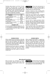
... disc motion at the contact point should parallel the grain as much , sanding action will be too great and a rough cut of the tool for producing the final finish. WARNING If the disc (accessory) is tilted too much as this first, the sanding discs will result. Test...steel, castings, sheet metal, stone ! Do not force or apply pressure when sanding. Excess pressure actually slows the tool down. Scratches and circular marks are intended to 15° angle while sanding so that were made by previous discs. To obtain best results, select sanding discs carefully. When changing to...
... disc motion at the contact point should parallel the grain as much , sanding action will be too great and a rough cut of the tool for producing the final finish. WARNING If the disc (accessory) is tilted too much as this first, the sanding discs will result. Test...steel, castings, sheet metal, stone ! Do not force or apply pressure when sanding. Excess pressure actually slows the tool down. Scratches and circular marks are intended to 15° angle while sanding so that were made by previous discs. To obtain best results, select sanding discs carefully. When changing to...

Operating Instructions
Page 11
... become noisy (due to use. CAUTION Certain cleaning agents and solvents damage plastic parts. rized Bosch Service Station. Some of foreign matter. Maintenance Service ! We recommend that tools with gears be replaced at once to six months the brushes be kept clean and free of...in full contact with compressed air. Do not attempt to wire fatigue. 3. Operate the brush with the work . Cleaning ! TOOL LUBRICATION Your Bosch tool has been properly lubricated and is continued, the life of the brush will result in contact with the lightest pressure so only ...
... become noisy (due to use. CAUTION Certain cleaning agents and solvents damage plastic parts. rized Bosch Service Station. Some of foreign matter. Maintenance Service ! We recommend that tools with gears be replaced at once to six months the brushes be kept clean and free of...in full contact with compressed air. Do not attempt to wire fatigue. 3. Operate the brush with the work . Cleaning ! TOOL LUBRICATION Your Bosch tool has been properly lubricated and is continued, the life of the brush will result in contact with the lightest pressure so only ...
Operating Instructions
Page 12
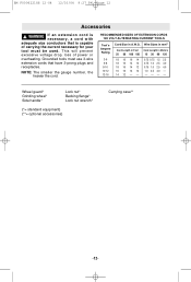
...-04 12/10/04 9:27 PM Page 12 Accessories ! This will prevent excessive voltage drop, loss of carrying the current necessary for your tool must use 3-wire extension cords that is necessary, a cord with adequate size conductors that have 3-prong plugs and receptacles. Wire Sizes in mm2 ...Cord Length in Feet Cord Length in A.W.G. RECOMMENDED SIZES OF EXTENSION CORDS 120 VOLT ALTERNATING CURRENT TOOLS Tool's Ampere Rating Cord Size in Meters 25 50 100 150 15 30 60 120 3-6 6-8 8-10 10-12 12-16 18 16 16 14...
...-04 12/10/04 9:27 PM Page 12 Accessories ! This will prevent excessive voltage drop, loss of carrying the current necessary for your tool must use 3-wire extension cords that is necessary, a cord with adequate size conductors that have 3-prong plugs and receptacles. Wire Sizes in mm2 ...Cord Length in Feet Cord Length in A.W.G. RECOMMENDED SIZES OF EXTENSION CORDS 120 VOLT ALTERNATING CURRENT TOOLS Tool's Ampere Rating Cord Size in Meters 25 50 100 150 15 30 60 120 3-6 6-8 8-10 10-12 12-16 18 16 16 14...
Parts List
Page 2
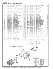
... (DC) 52 1 604 438 026 Cable 100mm The tool Must be wired as shown. 53 5/1 805 4.1 G F 4/1 F B 810 E 52 G 2 C C 54 E B 810 52 54 M CORD 53 + = Not Illustrated * = As Required F/C = Failure Code AW = Refer to AW Labor Time Chart 1347A 4-1/2" MINI GRINDER Pos. Part Number Description {Qty.} F/C 1 2 3... Fan 23 Switch On/Off 120V 15 w/pos. 4/1 Screw {2} 89 Terminal Sleeve {2} 11 Strain Relief 11 Cord Clamp 89 Label "1347A" 9 Ball Bearing 60 Ball Bearing 61 Brush Spring {2} 27 Switch Spring 27 Label "Caution" 9 Switch Slide 64 Switch Button 9 ...
... (DC) 52 1 604 438 026 Cable 100mm The tool Must be wired as shown. 53 5/1 805 4.1 G F 4/1 F B 810 E 52 G 2 C C 54 E B 810 52 54 M CORD 53 + = Not Illustrated * = As Required F/C = Failure Code AW = Refer to AW Labor Time Chart 1347A 4-1/2" MINI GRINDER Pos. Part Number Description {Qty.} F/C 1 2 3... Fan 23 Switch On/Off 120V 15 w/pos. 4/1 Screw {2} 89 Terminal Sleeve {2} 11 Strain Relief 11 Cord Clamp 89 Label "1347A" 9 Ball Bearing 60 Ball Bearing 61 Brush Spring {2} 27 Switch Spring 27 Label "Caution" 9 Switch Slide 64 Switch Button 9 ...

