

U8788 user's manual
Page 4
... and performance and strives for IDE devices such as Windows NT, Windows 2000, Windows ME, Windows XP, Novell, LINUX and SCO UNIX. 1-1 U8788 Features: 1.Contains on board I/O facilities that include two serial ports, a parallel port, a PS/2 mouse port, a PS/2 keyboard port, audio... such as hard disks and CD-ROM Drives. 3.Supports the Intel Pentium ® 4 processor, a leading edge processor. Chapter 1 Motherboard Description Notice Introduction of system This mainboard is designed to take advantage of its predecessors, this mainboard continues a commitment to provide you with...
... and performance and strives for IDE devices such as Windows NT, Windows 2000, Windows ME, Windows XP, Novell, LINUX and SCO UNIX. 1-1 U8788 Features: 1.Contains on board I/O facilities that include two serial ports, a parallel port, a PS/2 mouse port, a PS/2 keyboard port, audio... such as hard disks and CD-ROM Drives. 3.Supports the Intel Pentium ® 4 processor, a leading edge processor. Chapter 1 Motherboard Description Notice Introduction of system This mainboard is designed to take advantage of its predecessors, this mainboard continues a commitment to provide you with...
U8788 user's manual
Page 5
Runing at 400/533 MHz Front Side Bus frequency (Jumpless). 2. ITE 8705 DRAM Memory: 1. Chapter 1 Motherboard Description Mainboard Features 1. Provides Socket-478. 2. Supports the Intel Pentium ® 4 processor providing the new generation power for x8 and 16 devices. 3. The largest memory ...
Runing at 400/533 MHz Front Side Bus frequency (Jumpless). 2. ITE 8705 DRAM Memory: 1. Chapter 1 Motherboard Description Mainboard Features 1. Provides Socket-478. 2. Supports the Intel Pentium ® 4 processor providing the new generation power for x8 and 16 devices. 3. The largest memory ...
U8788 user's manual
Page 6
...: 1. Supports four IDE hard disk drives. 2. Supports high capacity hard disk drives. 7. Supports ESCD functionality. Has a power down timer from 1 to 133 MB/second. 4. Chapter 1 Motherboard Description Shadow RAM: Motherboard is equipped with CD-ROM. 6.
...: 1. Supports four IDE hard disk drives. 2. Supports high capacity hard disk drives. 7. Supports ESCD functionality. Has a power down timer from 1 to 133 MB/second. 4. Chapter 1 Motherboard Description Shadow RAM: Motherboard is equipped with CD-ROM. 6.

U8788 user's manual
Page 7
... Parallel Port (EPP). Mic in PCtel HSP56 Modem interface. 8. Legacy audio SBPRO compatible. 5. HRTF-based 3D positional audio, supporting DirectSound 3D and A3D interface. 3. Chapter 1 Motherboard Description AC'97 Sound Codec Onboard (Optional): 1. AC-LINK protocol comfliance. 2. SNR>95 Bb throughmixer and DAC. 5. Earphone buffer. 7. H/W Audio (Optional) 1. 6CH DAC for AC3...
... Parallel Port (EPP). Mic in PCtel HSP56 Modem interface. 8. Legacy audio SBPRO compatible. 5. HRTF-based 3D positional audio, supporting DirectSound 3D and A3D interface. 3. Chapter 1 Motherboard Description AC'97 Sound Codec Onboard (Optional): 1. AC-LINK protocol comfliance. 2. SNR>95 Bb throughmixer and DAC. 5. Earphone buffer. 7. H/W Audio (Optional) 1. 6CH DAC for AC3...
U8788 user's manual
Page 8
Dimensions (ATX form-factor): 30.5cm x 24.4cm (LxW) 1-5 Hardware Monitor Function: 1.Monitors CPU Fan Speed. 2.Monitors System Voltage. Chapter 1 Motherboard Description Universal Serial Bus V2.0: Supports two back panel Universal Serial Bus Port and four front panel Universal Serial Bus Ports.
Dimensions (ATX form-factor): 30.5cm x 24.4cm (LxW) 1-5 Hardware Monitor Function: 1.Monitors CPU Fan Speed. 2.Monitors System Voltage. Chapter 1 Motherboard Description Universal Serial Bus V2.0: Supports two back panel Universal Serial Bus Port and four front panel Universal Serial Bus Ports.
U8788 user's manual
Page 9
BIOS & Software 1.Award legal BIOS. 2.Supports APM1.2. 3.Supports USB Function. 4.Supports ACPI. Operating System: Offers the highest performance for ATX Case (Optional). 6.Fully Setup Driver CD. 1-6 Package Contents 1.HDD Cable. 2.FDD Cable. 3.Flash Memory Writer for BIOS Update. 4.USB Cable (Optional). 5.Rear I/O Panel for MS-DOS, Windows NT, Windows 2000, Windows ME, Windows XP, Novell, LINUX, and SCO UNIX etc. 1-3. Chapter 1 Motherboard Description 1-2.
BIOS & Software 1.Award legal BIOS. 2.Supports APM1.2. 3.Supports USB Function. 4.Supports ACPI. Operating System: Offers the highest performance for ATX Case (Optional). 6.Fully Setup Driver CD. 1-6 Package Contents 1.HDD Cable. 2.FDD Cable. 3.Flash Memory Writer for BIOS Update. 4.USB Cable (Optional). 5.Rear I/O Panel for MS-DOS, Windows NT, Windows 2000, Windows ME, Windows XP, Novell, LINUX, and SCO UNIX etc. 1-3. Chapter 1 Motherboard Description 1-2.
U8788 user's manual
Page 12
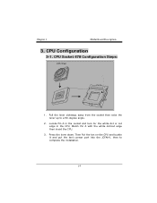
CPU Configuration 3-1. Locate Pin A in the socket and look for the white dot or cut edge then insert the CPU. 3. Press the lever down. CPU Socket 478 Configuration Steps: CPU Fan CPU 1. Then Put the fan on the CPU and buckle it and put the fan's power port into the JCFAN1, then to a 90-degree angle. 2. Pull the lever sideways away from the socket then raise the lever up to complete the installation. 1-9 Match Pin A with the white dot/cut edge in the CPU. Chapter 1 Motherboard Description 3.
CPU Configuration 3-1. Locate Pin A in the socket and look for the white dot or cut edge then insert the CPU. 3. Press the lever down. CPU Socket 478 Configuration Steps: CPU Fan CPU 1. Then Put the fan on the CPU and buckle it and put the fan's power port into the JCFAN1, then to a 90-degree angle. 2. Pull the lever sideways away from the socket then raise the lever up to complete the installation. 1-9 Match Pin A with the white dot/cut edge in the CPU. Chapter 1 Motherboard Description 3.
U8788 user's manual
Page 14
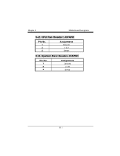
CPU Fan Header: JCFAN1 Pin No. 1 2 3 Assignment Ground +12V Sense 3-3. Chapter 1 Motherboard Description 3-2. System Fan Header: JSFAN1 Pin No. 1 2 3 Assignment Ground +12V Sense 1-11
CPU Fan Header: JCFAN1 Pin No. 1 2 3 Assignment Ground +12V Sense 3-3. Chapter 1 Motherboard Description 3-2. System Fan Header: JSFAN1 Pin No. 1 2 3 Assignment Ground +12V Sense 1-11
U8788 user's manual
Page 16
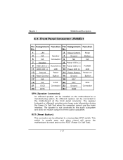
...Button) This connector can be connected to a momentary SPST switch. The speaker is usually open and when closed will cause the motherboard to the audio subsystem and does not receive output from the audio subsystem. An offboard speaker can be installed on 15 Reset Control... IrDA 20 KEY IrDA 21 VCC5 Connector 22 Ground Connector 23 IRTX 24 IRRX SPK (Speaker Connector) An offboard speaker can be attached to the motherboard at the front panel connector. No. 1 +5V 2 Sleep Control Sleep 3 NA Speaker 4 Ground Button 5 NA Connector 6 NA NA 7 Speaker 8 Power ...
...Button) This connector can be connected to a momentary SPST switch. The speaker is usually open and when closed will cause the motherboard to the audio subsystem and does not receive output from the audio subsystem. An offboard speaker can be installed on 15 Reset Control... IrDA 20 KEY IrDA 21 VCC5 Connector 22 Ground Connector 23 IRTX 24 IRRX SPK (Speaker Connector) An offboard speaker can be attached to the motherboard at the front panel connector. No. 1 +5V 2 Sleep Control Sleep 3 NA Speaker 4 Ground Button 5 NA Connector 6 NA NA 7 Speaker 8 Power ...
U8788 user's manual
Page 17
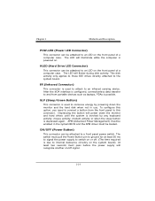
... to an infrared sensing device. The LED will flicker during disk activity. IR (Infrared Connector) This connector is powered on or off signal. 1-14 Chapter 1 Motherboard Description POW-LED (Power LED Connector) This connector can be attached to a front panel power switch.
... to an infrared sensing device. The LED will flicker during disk activity. IR (Infrared Connector) This connector is powered on or off signal. 1-14 Chapter 1 Motherboard Description POW-LED (Power LED Connector) This connector can be attached to a front panel power switch.
U8788 user's manual
Page 18
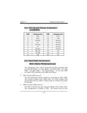
... has two HDD connectors IDE1 (primary) and IDE2 (secondary). • IDE1 (Primary IDE Connector) The first hard drive should always be connected to IDE1. Chapter 1 Motherboard Description 4-2. The configuration is similar to IDE1. Hard Disk Connectors: IDE1/IDE2/IDE3(Optional) This mainboard has a 32-bit Enhanced PCI IDE Controller that provides...
... has two HDD connectors IDE1 (primary) and IDE2 (secondary). • IDE1 (Primary IDE Connector) The first hard drive should always be connected to IDE1. Chapter 1 Motherboard Description 4-2. The configuration is similar to IDE1. Hard Disk Connectors: IDE1/IDE2/IDE3(Optional) This mainboard has a 32-bit Enhanced PCI IDE Controller that provides...
U8788 user's manual
Page 19
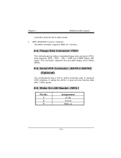
... a PCI to slave mode. • IDE3 (RAID IDE Conector) (Optional) The IDE3 controller supports RAID 0/1 Function. 4-4. Chapter 1 Motherboard Description controller must be set to SATA Controller with 2 channels STAT interface, it satisfy the SATA 1.0 spec and can transfer data with 1.5GHz speed. 4-6....JWOL1 Pin No. 1 2 3 Assignment 5V SB Ground Wake up 1-16 This connector supports the provided floppy drive ribbon cables. 4-5. Floppy Disk Connector: FDD1 The motherboard provides a standard floppy disk connector (FDC) that supports 360K, 720K, 1.2M, 1.44M and 2.88M floppy disk types.
... a PCI to slave mode. • IDE3 (RAID IDE Conector) (Optional) The IDE3 controller supports RAID 0/1 Function. 4-4. Chapter 1 Motherboard Description controller must be set to SATA Controller with 2 channels STAT interface, it satisfy the SATA 1.0 spec and can transfer data with 1.5GHz speed. 4-6....JWOL1 Pin No. 1 2 3 Assignment 5V SB Ground Wake up 1-16 This connector supports the provided floppy drive ribbon cables. 4-5. Floppy Disk Connector: FDD1 The motherboard provides a standard floppy disk connector (FDC) that supports 360K, 720K, 1.2M, 1.44M and 2.88M floppy disk types.
U8788 user's manual
Page 20
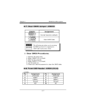
Front USB Header: JUSB3 (V2.0) (JUSB3) Pin 1 3 5 7 9 Assignment +5V(fused) USBP2USBP2+ Ground KEY Pin Assignment 2 +5V(fused) 4 USBP3- 6 USBP3+ 8 Ground 10 NC 1-17 Chapter 1 Motherboard Description 4-7. Make JCMOS1 (2-3) closed . 5. Make JCMOS1 (1-2) closed . 3. Remove AC power line. 2. Reset your desired password or clear the CMOS data. 4-8. Let AC power on. 6. Clear ...
Front USB Header: JUSB3 (V2.0) (JUSB3) Pin 1 3 5 7 9 Assignment +5V(fused) USBP2USBP2+ Ground KEY Pin Assignment 2 +5V(fused) 4 USBP3- 6 USBP3+ 8 Ground 10 NC 1-17 Chapter 1 Motherboard Description 4-7. Make JCMOS1 (2-3) closed . 5. Make JCMOS1 (1-2) closed . 3. Remove AC power line. 2. Reset your desired password or clear the CMOS data. 4-8. Let AC power on. 6. Clear ...
U8788 user's manual
Page 21
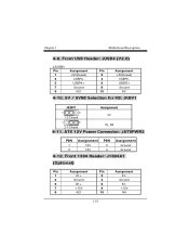
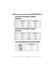
Front 1394 Header: J1394A1 (Optional) Pin Assignment Pin Assignment 1 A1+ 2 A1- 3 Ground 4 Ground 5 B1+ 6 B1- 7 +12V 8 +12V 9 KEY 10 NA 1-18 Chapter 1 Motherboard Description 4-9. ATX 12V Power Connector: JATXPWR2 PIN 1 2 Assignment 12V 12V PIN 3 4 Assignment Ground Ground 4-12. Front USB Header: JUSB4 (V2.0) (JUSB4) Pin 1 3 5 7 9 Assignment +5V(fused) ...
Front 1394 Header: J1394A1 (Optional) Pin Assignment Pin Assignment 1 A1+ 2 A1- 3 Ground 4 Ground 5 B1+ 6 B1- 7 +12V 8 +12V 9 KEY 10 NA 1-18 Chapter 1 Motherboard Description 4-9. ATX 12V Power Connector: JATXPWR2 PIN 1 2 Assignment 12V 12V PIN 3 4 Assignment Ground Ground 4-12. Front USB Header: JUSB4 (V2.0) (JUSB4) Pin 1 3 5 7 9 Assignment +5V(fused) ...
U8788 user's manual
Page 22
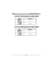
Front 1394 Header: J1394B1 (Optional) Pin Assignment Pin Assignment 1 A2+ 2 A2- 3 Ground 4 Ground 5 B2+ 6 B2- 7 +12V 8 +12V 9 KEY 10 NA 4-14. Front 1394 Header: J1394C1 (Optional) Pin Assignment Pin Assignment 1 A3+ 2 A3- 3 Ground 4 Ground 5 B3+ 6 B3- 7 +12V 8 +12V 9 KEY 10 NA 4-15. 5V/ 5VSB Selection for USB: JUSBV1 JUSBV1 1 3 1-2 Closed 1 3 2-3 Closed Assignment 5V 5V_SB 1-19 Chapter 1 Motherboard Description 4-13.
Front 1394 Header: J1394B1 (Optional) Pin Assignment Pin Assignment 1 A2+ 2 A2- 3 Ground 4 Ground 5 B2+ 6 B2- 7 +12V 8 +12V 9 KEY 10 NA 4-14. Front 1394 Header: J1394C1 (Optional) Pin Assignment Pin Assignment 1 A3+ 2 A3- 3 Ground 4 Ground 5 B3+ 6 B3- 7 +12V 8 +12V 9 KEY 10 NA 4-15. 5V/ 5VSB Selection for USB: JUSBV1 JUSBV1 1 3 1-2 Closed 1 3 2-3 Closed Assignment 5V 5V_SB 1-19 Chapter 1 Motherboard Description 4-13.
U8788 user's manual
Page 23
Chapter 1 Motherboard Description 4-16. 5V/ 5VSB Selection for USB: JUSBV3 JUSBV1 1 3 1-2 Closed 1 3 2-3 Closed Assignment 5V 5V_SB 4-17. 5V/ 5VSB Selection for USB: JUSBV4 JUSBV1 1 3 1-2 Closed 1 3 2-3 Closed Assignment 5V 5V_SB 1-20
Chapter 1 Motherboard Description 4-16. 5V/ 5VSB Selection for USB: JUSBV3 JUSBV1 1 3 1-2 Closed 1 3 2-3 Closed Assignment 5V 5V_SB 4-17. 5V/ 5VSB Selection for USB: JUSBV4 JUSBV1 1 3 1-2 Closed 1 3 2-3 Closed Assignment 5V 5V_SB 1-20
U8788 user's manual
Page 24
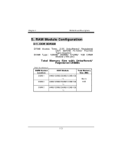
Chapter 1 Motherboard Description 5. DRAM Type: 128MB/ 256MB/ 512MB/ 1GB DIMM Module (184 pin) Total Memory Size with Unbuffered/ Registered DIMMs (Only for reference) DIMM Socket Location DDR Module Total Memory Size (MB) DIMM 1 64MB/128MB/256MB/512MB/1GB *1 Max is DIMM 2 64MB/128MB/256MB/512MB/1GB 3GB *1 DIMM 3 64MB/128MB/256MB/512MB/1GB *1 1-21 DDR SDRAM DRAM Access Time: 2.5V Unbuffered/ Registered DDR SDRAM PC1600/ PC2100 Type required. RAM Module Configuration 5-1.
Chapter 1 Motherboard Description 5. DRAM Type: 128MB/ 256MB/ 512MB/ 1GB DIMM Module (184 pin) Total Memory Size with Unbuffered/ Registered DIMMs (Only for reference) DIMM Socket Location DDR Module Total Memory Size (MB) DIMM 1 64MB/128MB/256MB/512MB/1GB *1 Max is DIMM 2 64MB/128MB/256MB/512MB/1GB 3GB *1 DIMM 3 64MB/128MB/256MB/512MB/1GB *1 1-21 DDR SDRAM DRAM Access Time: 2.5V Unbuffered/ Registered DDR SDRAM PC1600/ PC2100 Type required. RAM Module Configuration 5-1.
U8788 user's manual
Page 26
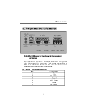
... definition are shown below: PS/2 Mouse / Keyboard Connectors Pin 1 2 3 4 5 6 Assignment Data No connect Ground +5 V (fused) Clock No connect 23 PS/2 Mouse / Keyboard Connector: JKBMS1 The motherboard provides a standard PS/2 mouse / Keyboard mini DIN connector for attaching a PS/2 mouse. Peripheral Port Features JKBMS1 PS/2 JUSBLAN1 Mouse LAN JPRNT1 Parallel JAUD_GAME Game Port...
... definition are shown below: PS/2 Mouse / Keyboard Connectors Pin 1 2 3 4 5 6 Assignment Data No connect Ground +5 V (fused) Clock No connect 23 PS/2 Mouse / Keyboard Connector: JKBMS1 The motherboard provides a standard PS/2 mouse / Keyboard mini DIN connector for attaching a PS/2 mouse. Peripheral Port Features JKBMS1 PS/2 JUSBLAN1 Mouse LAN JPRNT1 Parallel JAUD_GAME Game Port...

U8788 compatibility test report
Page 2
CONTENTS PRODUCT INFORMATION 4 Motherboard General Information 4 Chipset Details...4 BIOS Details...4 CPU Supports...4 Memory Supports 4 On-board Features and Devices 4 Mechanical...5 DESIGN REVIEW-Ver3.0 7 Mainboard Voltage Measurement 7 Bus Clock ...7 REQUIRED ...
CONTENTS PRODUCT INFORMATION 4 Motherboard General Information 4 Chipset Details...4 BIOS Details...4 CPU Supports...4 Memory Supports 4 On-board Features and Devices 4 Mechanical...5 DESIGN REVIEW-Ver3.0 7 Mainboard Voltage Measurement 7 Bus Clock ...7 REQUIRED ...
U8788 compatibility test report
Page 4
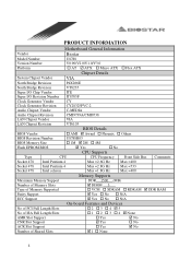
... CY28325PVC-2 Audio Chipset Vendor C-MEDIA Audio Chipset Revision LAN Chipset Vendor LAN Chipset Revision CMI9739A/CMI8738 VIA VT6103 BIOS Vendor BIOS Details ! No ! PRODUCT INFORMATION Motherboard General Information Vendor Biostar Model Number Version Number Platform U8788 V0.90/V2.0/V1.0/V3.0 ! AT " ATX !
... CY28325PVC-2 Audio Chipset Vendor C-MEDIA Audio Chipset Revision LAN Chipset Vendor LAN Chipset Revision CMI9739A/CMI8738 VIA VT6103 BIOS Vendor BIOS Details ! No ! PRODUCT INFORMATION Motherboard General Information Vendor Biostar Model Number Version Number Platform U8788 V0.90/V2.0/V1.0/V3.0 ! AT " ATX !

