
TForce4 U user's manual
Page 3
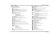
.... Supports ACPI power management. NVIDIA Active Armor (Only for TForce4 Ultra. One CD-ROM audio-in fastest networking performance. Four SATA ports. Back Panel I /O Chip: ITE IT8712F. NVIDIA nForce4 Ultra for nForce4 Ultra) Enhances network security, and provides users with data... rates up to 3Gb/s. Two Ultra DMA 133/100/66/33 IDE connectors. Biostar T-Series Chapter 1: Introduction 1.1 MOTHERBOARD FEATURES CPU Supports Socket 939. Supports PIO mode 0~4, Block Mode and Ultra DMA 33/66/100/133 bus master mode. 1 TForce4/ TForce4 U AC'97 Audio Sound Codec...
.... Supports ACPI power management. NVIDIA Active Armor (Only for TForce4 Ultra. One CD-ROM audio-in fastest networking performance. Four SATA ports. Back Panel I /O Chip: ITE IT8712F. NVIDIA nForce4 Ultra for nForce4 Ultra) Enhances network security, and provides users with data... rates up to 3Gb/s. Two Ultra DMA 133/100/66/33 IDE connectors. Biostar T-Series Chapter 1: Introduction 1.1 MOTHERBOARD FEATURES CPU Supports Socket 939. Supports PIO mode 0~4, Block Mode and Ultra DMA 33/66/100/133 bus master mode. 1 TForce4/ TForce4 U AC'97 Audio Sound Codec...
TForce4 U user's manual
Page 4
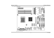
Biostar T-Series 1.2 LAYOUT AND COMPONENTS JATXPWR1 JDDR_0V>3V JCFAN1 DIMM3 DIMM1 DIMM4 DIMM2 Socket 939 JNBFAN1 nForce4 or nForce4 Ultra IDE2 IDE1 LED_D1 LED_D2 LED_DIMM LED_5SB FDD1 TForce4/ TForce4 U JSATA4 JSATA3 JSATA2 JSATA1 JCMOS1 JUSBV1 JUSB3 JUSB2 JUSB1 JCI1 JSFAN1 BAT1 RSTSW PWRSW JPANEL1 BIOS Super I/O JSFAN2 J1394A1 PCI-EX16 XGP1 JATXPWR2 JKBMSV1 J1394_USBV1 ...
Biostar T-Series 1.2 LAYOUT AND COMPONENTS JATXPWR1 JDDR_0V>3V JCFAN1 DIMM3 DIMM1 DIMM4 DIMM2 Socket 939 JNBFAN1 nForce4 or nForce4 Ultra IDE2 IDE1 LED_D1 LED_D2 LED_DIMM LED_5SB FDD1 TForce4/ TForce4 U JSATA4 JSATA3 JSATA2 JSATA1 JCMOS1 JUSBV1 JUSB3 JUSB2 JUSB1 JCI1 JSFAN1 BAT1 RSTSW PWRSW JPANEL1 BIOS Super I/O JSFAN2 J1394A1 PCI-EX16 XGP1 JATXPWR2 JKBMSV1 J1394_USBV1 ...
TForce4 U user's manual
Page 7
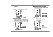
TForce4/ TForce4 U Peripheral Component Interconnect Slots: PCI1~PCI3 This motherboard is ...Slots PCI-EX16: - Maximum bandwidth is up to IDE1. This connector supports the provided floppy drive ribbon cables. Biostar T-Series 2.3 PERIPHERALS A. It has two HDD connectors IDE1 (primary) and IDE2 (secondary). Card and I/O Slots... Floppy Disk Connector: FDD1 The motherboard provides a standard floppy disk connector that provide PIO Mode 0~4, Bus Master, and Ultra DMA 33/66/100/133 functionality. PEX1-1/PEX1-2: - Maximum bandwidth is up to 4GB/s per direction. 39 IDE2 ...
TForce4/ TForce4 U Peripheral Component Interconnect Slots: PCI1~PCI3 This motherboard is ...Slots PCI-EX16: - Maximum bandwidth is up to IDE1. This connector supports the provided floppy drive ribbon cables. Biostar T-Series 2.3 PERIPHERALS A. It has two HDD connectors IDE1 (primary) and IDE2 (secondary). Card and I/O Slots... Floppy Disk Connector: FDD1 The motherboard provides a standard floppy disk connector that provide PIO Mode 0~4, Bus Master, and Ultra DMA 33/66/100/133 functionality. PEX1-1/PEX1-2: - Maximum bandwidth is up to 4GB/s per direction. 39 IDE2 ...
TForce4 U user's manual
Page 11
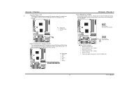
Biostar T-Series Case Open Header: JCI1 This connector allows system to monitor PC case open signal 2 Ground JCI1 12 Codec BIOS Serial ATA Connectors: JSATA1~JSATA4 The motherboard has an SATA Controller in nForce4 CK8-04 and CK8-04 Ultra with 4 channels SATA interface, it satisfies the ... data. 9 User's Manual JSATA1 JSATA2 JSATA3 JSATA4 7 41 Pin Assignment 1 Ground 2 TX+ 3 TX4 Ground 5 RX6 RX+ 7 Ground Codec BIOS TForce4/ TForce4 U Clear CMOS Header: JCMOS1 By placing the jumper on pin 2-3, it will record to avoid damaging the motherboard. 13 Pin 1-2 Close: Normal Operation (...
Biostar T-Series Case Open Header: JCI1 This connector allows system to monitor PC case open signal 2 Ground JCI1 12 Codec BIOS Serial ATA Connectors: JSATA1~JSATA4 The motherboard has an SATA Controller in nForce4 CK8-04 and CK8-04 Ultra with 4 channels SATA interface, it satisfies the ... data. 9 User's Manual JSATA1 JSATA2 JSATA3 JSATA4 7 41 Pin Assignment 1 Ground 2 TX+ 3 TX4 Ground 5 RX6 RX+ 7 Ground Codec BIOS TForce4/ TForce4 U Clear CMOS Header: JCMOS1 By placing the jumper on pin 2-3, it will record to avoid damaging the motherboard. 13 Pin 1-2 Close: Normal Operation (...