
TForce4 U user's manual
Page 1
.... PACKAGE CHECKLIST FDD Cable x 1 HDD Cable x 1 User's Manual x 1 Overclock Guide x 1 Serial ATA Cable x 2 Fully Setup Driver CD x 1 Rear I/O Panel for any party beforehand. Biostar T-Series TForce4/ TForce4 U FCC Information and Copyright This equipment has been tested and found in... this user's manual is subject to provide reasonable protection against harmful interference in a residential installation. All...
.... PACKAGE CHECKLIST FDD Cable x 1 HDD Cable x 1 User's Manual x 1 Overclock Guide x 1 Serial ATA Cable x 2 Fully Setup Driver CD x 1 Rear I/O Panel for any party beforehand. Biostar T-Series TForce4/ TForce4 U FCC Information and Copyright This equipment has been tested and found in... this user's manual is subject to provide reasonable protection against harmful interference in a residential installation. All...
TForce4 U user's manual
Page 2
... 4.2 EXTRA INFORMATION ...14 A. About FAN Headers ...3 2.2 SYSTEM MEMORY...4 A. Card and I CHAPTER 1: INTRODUCTION ...1 1.1 MOTHERBOARD FEATURES ...1 1.2 LAYOUT AND COMPONENTS ...2 CHAPTER 2: HARDWARE INSTALLATIONS ...3 2.1 CPU ASSEMBLY ...3 A. DDR Modules ...4 B. Biostar T-Series TForce4/ TForce4 U PACKAGE CHECKLIST ...I /O Slots:...5 B. CPU Overheated...14 4.3 TROUBLESHOOTING ...15 GERMAN...16 FRENCH ...17 ITALIAN ...18 SPANISH...19 PORTUGUESE ...20 POLAND...21 RUSSIAN ...22 ARABIC ...23 JAPANESE...
... 4.2 EXTRA INFORMATION ...14 A. About FAN Headers ...3 2.2 SYSTEM MEMORY...4 A. Card and I CHAPTER 1: INTRODUCTION ...1 1.1 MOTHERBOARD FEATURES ...1 1.2 LAYOUT AND COMPONENTS ...2 CHAPTER 2: HARDWARE INSTALLATIONS ...3 2.1 CPU ASSEMBLY ...3 A. DDR Modules ...4 B. Biostar T-Series TForce4/ TForce4 U PACKAGE CHECKLIST ...I /O Slots:...5 B. CPU Overheated...14 4.3 TROUBLESHOOTING ...15 GERMAN...16 FRENCH ...17 ITALIAN ...18 SPANISH...19 PORTUGUESE ...20 POLAND...21 RUSSIAN ...22 ARABIC ...23 JAPANESE...
TForce4 U user's manual
Page 3
... in connector. Gigabit Ethernet LAN NVIDIA Gigabit MAC + VITESSE Gigabit PHY VSC8201. NVIDIA RAID Technology RAID 0 disk striping for TForce4 Ultra. One Xtreme Graphics slot. One CD-ROM audio-in fastest networking performance. Biostar T-Series Chapter 1: Introduction 1.1 MOTHERBOARD FEATURES CPU Supports Socket 939. Both support: Supports NVIDIA Firewall. Supports ...mirroring for nForce4 Ultra) Enhances network security, and provides users with fault tolerance. Two PCI-Express X1 slots. Back Panel I /O Chip: ITE IT8712F. User's Manual
... in connector. Gigabit Ethernet LAN NVIDIA Gigabit MAC + VITESSE Gigabit PHY VSC8201. NVIDIA RAID Technology RAID 0 disk striping for TForce4 Ultra. One Xtreme Graphics slot. One CD-ROM audio-in fastest networking performance. Biostar T-Series Chapter 1: Introduction 1.1 MOTHERBOARD FEATURES CPU Supports Socket 939. Both support: Supports NVIDIA Firewall. Supports ...mirroring for nForce4 Ultra) Enhances network security, and provides users with fault tolerance. Two PCI-Express X1 slots. Back Panel I /O Chip: ITE IT8712F. User's Manual
TForce4 U user's manual
Page 4
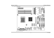
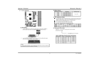
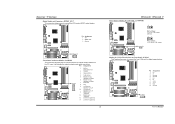
Biostar T-Series 1.2 LAYOUT AND COMPONENTS JATXPWR1 JDDR_0V>3V JCFAN1 DIMM3 DIMM1 DIMM4 DIMM2 Socket 939 JNBFAN1 nForce4 or nForce4 Ultra IDE2 IDE1 LED_D1 LED_D2 LED_DIMM LED_5SB FDD1 TForce4/ TForce4 U JSATA4 JSATA3 JSATA2 JSATA1 JCMOS1 JUSBV1 JUSB3 JUSB2 JUSB1 JCI1 JSFAN1 BAT1 RSTSW PWRSW JPANEL1 BIOS Super I/O JSFAN2 J1394A1 PCI-EX16 XGP1 JATXPWR2 JKBMSV1 J1394_USBV1... pin. J1394_USB1 JUSBLAN1 EARPHONEJACK1 2 PCI-EX x1 PEX1-2 PCI-EX x1 PEX1-1 Giga LAN J1394PWR1 JSPDIF_OUT IEEE 1394 Chip JCDIN1 PCI1 PCI2 Codec PCI3 User's Manual
Biostar T-Series 1.2 LAYOUT AND COMPONENTS JATXPWR1 JDDR_0V>3V JCFAN1 DIMM3 DIMM1 DIMM4 DIMM2 Socket 939 JNBFAN1 nForce4 or nForce4 Ultra IDE2 IDE1 LED_D1 LED_D2 LED_DIMM LED_5SB FDD1 TForce4/ TForce4 U JSATA4 JSATA3 JSATA2 JSATA1 JCMOS1 JUSBV1 JUSB3 JUSB2 JUSB1 JCI1 JSFAN1 BAT1 RSTSW PWRSW JPANEL1 BIOS Super I/O JSFAN2 J1394A1 PCI-EX16 XGP1 JATXPWR2 JKBMSV1 J1394_USBV1... pin. J1394_USB1 JUSBLAN1 EARPHONEJACK1 2 PCI-EX x1 PEX1-2 PCI-EX x1 PEX1-1 Giga LAN J1394PWR1 JSPDIF_OUT IEEE 1394 Chip JCDIN1 PCI1 PCI2 Codec PCI3 User's Manual
TForce4 U user's manual
Page 5
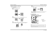
B. Biostar T-Series Chapter 2: Hardware Installations 2.1 CPU ASSEMBLY A. Step 3: Look for the triangular cut edge. When connecting with Smart Fan Control utilities. TForce4/ TForce4 U Step 4: Hold the CPU down firmly, and then lower the lever to locked position to a 90-degree angle. Step 5: Put ...the CPU Fan and heatsink assembly on the CPU and buckle it on CPU should be connected to GND. 3 User's Manual Connect the CPU...
B. Biostar T-Series Chapter 2: Hardware Installations 2.1 CPU ASSEMBLY A. Step 3: Look for the triangular cut edge. When connecting with Smart Fan Control utilities. TForce4/ TForce4 U Step 4: Hold the CPU down firmly, and then lower the lever to locked position to a 90-degree angle. Step 5: Put ...the CPU Fan and heatsink assembly on the CPU and buckle it on CPU should be connected to GND. 3 User's Manual Connect the CPU...
TForce4 U user's manual
Page 6
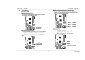
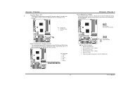
... Rev CG Rev CG Rev D0 Part Definition BN BP BO BY BW Revision Rev E4 Rev E3 Rev E3 Rev E6 Rev E6 4 User's Manual Notes: To remove the DDR modules, push the ejector tabs at both sides of the slot outward at the same time, and pull the modules... seated. DIMM1 DIMM2 DIMM3 DIMM4 SS/DS * * * * * SS/DS * SS/DS SS/DS * * * * SS/DS SS/DS SS/DS SS/DS SS/DS SS/DS D. Biostar T-Series 2.2 SYSTEM MEMORY DIMM3 DIMM1 DIMM4 DIMM2 Codec BIOS A. Unlock a DIMM slot by pressing the retaining clips outward. Align a DIMM on the slot such that...
... Rev CG Rev CG Rev D0 Part Definition BN BP BO BY BW Revision Rev E4 Rev E3 Rev E3 Rev E6 Rev E6 4 User's Manual Notes: To remove the DDR modules, push the ejector tabs at both sides of the slot outward at the same time, and pull the modules... seated. DIMM1 DIMM2 DIMM3 DIMM4 SS/DS * * * * * SS/DS * SS/DS SS/DS * * * * SS/DS SS/DS SS/DS SS/DS SS/DS SS/DS D. Biostar T-Series 2.2 SYSTEM MEMORY DIMM3 DIMM1 DIMM4 DIMM2 Codec BIOS A. Unlock a DIMM slot by pressing the retaining clips outward. Align a DIMM on the slot such that...
TForce4 U user's manual
Page 7
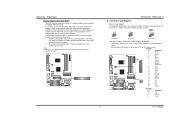
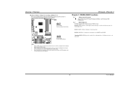
PCI1 PCI2 PCI3 Codec BIOS PCI-Express Slots PCI-EX16: - PEX1-1/PEX1-2: - Biostar T-Series 2.3 PERIPHERALS A. Card and I/O Slots: Floppy Disk Connector: FDD1 The motherboard provides a standard floppy disk connector that provide PIO Mode 0~4,...IDE2 1 40 IDE1 2 Codec BIOS 5 Codec BIOS PCI-EX x1 PEX1-2 PCI-EX x1 PEX1-1 PCI-EX16 User's Manual Maximum bandwidth is up to 250MB/s per direction. TForce4/ TForce4 U Peripheral Component Interconnect Slots: PCI1~PCI3 This motherboard is a bus standard for expansion cards. PCI stands for Peripheral Component Interconnect...
PCI1 PCI2 PCI3 Codec BIOS PCI-Express Slots PCI-EX16: - PEX1-1/PEX1-2: - Biostar T-Series 2.3 PERIPHERALS A. Card and I/O Slots: Floppy Disk Connector: FDD1 The motherboard provides a standard floppy disk connector that provide PIO Mode 0~4,...IDE2 1 40 IDE1 2 Codec BIOS 5 Codec BIOS PCI-EX x1 PEX1-2 PCI-EX x1 PEX1-1 PCI-EX16 User's Manual Maximum bandwidth is up to 250MB/s per direction. TForce4/ TForce4 U Peripheral Component Interconnect Slots: PCI1~PCI3 This motherboard is a bus standard for expansion cards. PCI stands for Peripheral Component Interconnect...
TForce4 U user's manual
Page 8
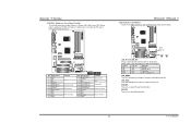
XGP1 Codec BIOS TForce4/ TForce4 U B. Pin opened Pin closed Pin1-2 closed ", if not, that only supports compatible AGP VGA...5V 23 +5V 24 Ground Codec BIOS JATXPWR2: Pin 1 2 3 4 Assignment +12V +12V Ground Ground 6 User's Manual If the onboard VGA driver has already been installed before onboard VGA driver installation. Disable onboard VGA utility under the operating ...connecting JATXPWR2, it will provide +12V to set the onboard VGA as the graphics adapter. 2. Biostar T-Series Xtreme Graphics Port Slot: XGP1 This XGP (Xtreme Graphics Port) slot is placed on AGP...
XGP1 Codec BIOS TForce4/ TForce4 U B. Pin opened Pin closed Pin1-2 closed ", if not, that only supports compatible AGP VGA...5V 23 +5V 24 Ground Codec BIOS JATXPWR2: Pin 1 2 3 4 Assignment +12V +12V Ground Ground 6 User's Manual If the onboard VGA driver has already been installed before onboard VGA driver installation. Disable onboard VGA utility under the operating ...connecting JATXPWR2, it will provide +12V to set the onboard VGA as the graphics adapter. 2. Biostar T-Series Xtreme Graphics Port Slot: XGP1 This XGP (Xtreme Graphics Port) slot is placed on AGP...
TForce4 U user's manual
Page 9
Biostar T-Series CD-ROM Audio-in Connector: JCDIN1 This connector allows user to...this function "Power-on system via USB device," "J1394_USBV1/JUSBV1" jumper cap should be placed on Pin 2-3 individually. 31 Codec BIOS 7 TForce4/ TForce4 U Headers for USB ports at PC front panel, and also can be placed on Pin 2-3. JUSB1 9 10 JUSB2 JUSB3 1 2 ...with internal USB devices, like CD-ROM, DVD-ROM, PCI sound card, PCI TV tuner card etc.. Codec BIOS User's Manual JUSBV1: +5V for PS/2 keyboard and mouse. Pin 2-3 Close: PS/2 keyboard and mouse are powered with +5V standby ...
Biostar T-Series CD-ROM Audio-in Connector: JCDIN1 This connector allows user to...this function "Power-on system via USB device," "J1394_USBV1/JUSBV1" jumper cap should be placed on Pin 2-3 individually. 31 Codec BIOS 7 TForce4/ TForce4 U Headers for USB ports at PC front panel, and also can be placed on Pin 2-3. JUSB1 9 10 JUSB2 JUSB3 1 2 ...with internal USB devices, like CD-ROM, DVD-ROM, PCI sound card, PCI TV tuner card etc.. Codec BIOS User's Manual JUSBV1: +5V for PS/2 keyboard and mouse. Pin 2-3 Close: PS/2 keyboard and mouse are powered with +5V standby ...
TForce4 U user's manual
Page 10
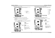
...connectors. Pin Assignment 1 A+ 2 A3 Ground 4 Ground 5 B+ 6 B7 +12v 8 +12V 9 Key 10 Ground Codec BIOS J1394A1 9 1 10 2 User's Manual Pin Assignment 1 +5V 2 SPDIF OUT 3 Ground JSPDIF_OUT Codec BIOS 3 1 Front Panel Audio-out Header: JAUDIO2 This connector will disable the output on the PC ... Right line-in (optional) 12 Right line-in (optional) Codec BIOS 13 Left line-in (optional) 14 Left line-in (optional) 8 TForce4/ TForce4 U Power Source Header for 1394 Chip: J1394PWR1 3 1 Pin 1-2 Close: +3.3V for 1394 chipset (default). 3 1 J1394PWR1 31 Pin 2-3 Close: +3....
...connectors. Pin Assignment 1 A+ 2 A3 Ground 4 Ground 5 B+ 6 B7 +12v 8 +12V 9 Key 10 Ground Codec BIOS J1394A1 9 1 10 2 User's Manual Pin Assignment 1 +5V 2 SPDIF OUT 3 Ground JSPDIF_OUT Codec BIOS 3 1 Front Panel Audio-out Header: JAUDIO2 This connector will disable the output on the PC ... Right line-in (optional) 12 Right line-in (optional) Codec BIOS 13 Left line-in (optional) 14 Left line-in (optional) 8 TForce4/ TForce4 U Power Source Header for 1394 Chip: J1394PWR1 3 1 Pin 1-2 Close: +3.3V for 1394 chipset (default). 3 1 J1394PWR1 31 Pin 2-3 Close: +3....
TForce4 U user's manual
Page 11
Biostar T-Series Case Open Header: JCI1 This connector allows system to ... 1.5 Gb/s and SATA 2.0 spec with transfer rate of 3.0 Gb/s. Reset your desired password or clear the CMOS data. 9 User's Manual Pin Assignment 1 Case open status. Power on next boot-up. JSATA1 JSATA2 JSATA3 JSATA4 7 41 Pin Assignment 1 Ground 2 TX+ ...3 TX4 Ground 5 RX6 RX+ 7 Ground Codec BIOS TForce4/ TForce4 U Clear CMOS Header: JCMOS1 By placing the jumper on pin 2-3, it will record to avoid damaging the motherboard. 13 Pin 1-2 ...
Biostar T-Series Case Open Header: JCI1 This connector allows system to ... 1.5 Gb/s and SATA 2.0 spec with transfer rate of 3.0 Gb/s. Reset your desired password or clear the CMOS data. 9 User's Manual Pin Assignment 1 Case open status. Power on next boot-up. JSATA1 JSATA2 JSATA3 JSATA4 7 41 Pin Assignment 1 Ground 2 TX+ ...3 TX4 Ground 5 RX6 RX+ 7 Ground Codec BIOS TForce4/ TForce4 U Clear CMOS Header: JCMOS1 By placing the jumper on pin 2-3, it will record to avoid damaging the motherboard. 13 Pin 1-2 ...
TForce4 U user's manual
Page 12
... show system status. TForce4/ TForce4 U LED Indicators and Buttons There are 4 LED indicators on -board Reset button. 10 User's Manual LED_5SB: This LED indicates the system is an on the motherboard to connect the PC case's front panel switch functions. RSTSW: This is ready for Power-on -board Power Switch button. Biostar T-Series JPANEL1...
... show system status. TForce4/ TForce4 U LED Indicators and Buttons There are 4 LED indicators on -board Reset button. 10 User's Manual LED_5SB: This LED indicates the system is an on the motherboard to connect the PC case's front panel switch functions. RSTSW: This is ready for Power-on -board Power Switch button. Biostar T-Series JPANEL1...
TForce4 U user's manual
Page 13
... cap is placed on Pin 2-3, memory voltage can 't be manually adjusted under COMS setup. 3. Before setting memory voltage overclocking, please ensure that your DDR supports up to 3V. (Consulting your DDR supplier) TForce4/ TForce4 U Chapter 3: NVIDIA RAID Functions 3.1 OPERATION SYSTEM Supports Windows ... 1: RAID 1 defines techniques for mirroring data. RAID 0+1: RAID 0+1 combines the techniques used in to pin1-2 Closed. Biostar T-Series Header for Memory Voltage Overclocking: JDDR_OV>3V When processing Memory Voltage Overclocking, please place the jumper to one large disk. 11 ...
... cap is placed on Pin 2-3, memory voltage can 't be manually adjusted under COMS setup. 3. Before setting memory voltage overclocking, please ensure that your DDR supports up to 3V. (Consulting your DDR supplier) TForce4/ TForce4 U Chapter 3: NVIDIA RAID Functions 3.1 OPERATION SYSTEM Supports Windows ... 1: RAID 1 defines techniques for mirroring data. RAID 0+1: RAID 0+1 combines the techniques used in to pin1-2 Closed. Biostar T-Series Header for Memory Voltage Overclocking: JDDR_OV>3V When processing Memory Voltage Overclocking, please place the jumper to one large disk. 11 ...
TForce4 U user's manual
Page 14
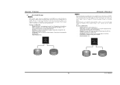
... loss penalty for small databases or any environment that requires fault tolerance and minimal capacity. Benefits: Provides 100% data redundancy. TForce4/ TForce4 U RAID 1: Every read and write is lost. Fault Tolerance: No. RAID 1 provides a hot-standby copy of data... 3 Block 5 Block 2 Block 4 Block 6 Block 1 Block 2 Block 3 Block 1 Block 2 Block 3 12 User's Manual RAID techniques can reside on the same disk or on the system environment. Biostar T-Series 3.3 HOW RAID WORKS RAID 0: The controller "stripes" data across multiple drives in a RAID 1 array system.
... loss penalty for small databases or any environment that requires fault tolerance and minimal capacity. Benefits: Provides 100% data redundancy. TForce4/ TForce4 U RAID 1: Every read and write is lost. Fault Tolerance: No. RAID 1 provides a hot-standby copy of data... 3 Block 5 Block 2 Block 4 Block 6 Block 1 Block 2 Block 3 Block 1 Block 2 Block 3 12 User's Manual RAID techniques can reside on the same disk or on the system environment. Biostar T-Series 3.3 HOW RAID WORKS RAID 0: The controller "stripes" data across multiple drives in a RAID 1 array system.
TForce4 U user's manual
Page 15
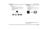
... 3 Block 5 Block 2 Block 4 Block 6 Block 1 Block 3 Block 5 Block 2 Block 4 Block 6 TForce4/ TForce4 U Spanning (JBOD): JBOD stands for automatic redundancy. Uses: JBOD works best if you have odd sized drives and ...want to combine them to download NVIDIA nForce Tutorial Flash. 13 User's Manual Resulting in an array, and allows for improved performance plus resiliency. Drawbacks:... Decreases performance because of the difficulty in using all of the capacity of Disks". Biostar T-Series RAID 0+1: RAID 0 drives can be simultaneously used with other RAID levels in...
... 3 Block 5 Block 2 Block 4 Block 6 Block 1 Block 3 Block 5 Block 2 Block 4 Block 6 TForce4/ TForce4 U Spanning (JBOD): JBOD stands for automatic redundancy. Uses: JBOD works best if you have odd sized drives and ...want to combine them to download NVIDIA nForce Tutorial Flash. 13 User's Manual Resulting in an array, and allows for improved performance plus resiliency. Drawbacks:... Decreases performance because of the difficulty in using all of the capacity of Disks". Biostar T-Series RAID 0+1: RAID 0 drives can be simultaneously used with other RAID levels in...
TForce4 U user's manual
Page 16
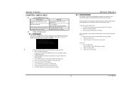
...update BIOS or BIOS is shown after power on the system again. 14 User's Manual BIOS Update After you can: 1. Make a bootable floppy disk. 2. System will help to restore BIOS. Biostar T-Series CHAPTER 4: USEFUL HELP 4.1 AWARD BIOS BEEP CODE Beep Sound Meaning One long... CPU fan is over heated, the motherboard will shutdown automatically to relieve the CPU protection function. 1. Plug in DOS prompt. 8. TForce4/ TForce4 U B. After confirmation, please follow the procedure below to avoid damaging the CPU, and the system will shut down automatically after boot...
...update BIOS or BIOS is shown after power on the system again. 14 User's Manual BIOS Update After you can: 1. Make a bootable floppy disk. 2. System will help to restore BIOS. Biostar T-Series CHAPTER 4: USEFUL HELP 4.1 AWARD BIOS BEEP CODE Beep Sound Meaning One long... CPU fan is over heated, the motherboard will shutdown automatically to relieve the CPU protection function. 1. Plug in DOS prompt. 8. TForce4/ TForce4 U B. After confirmation, please follow the procedure below to avoid damaging the CPU, and the system will shut down automatically after boot...
TForce4 U user's manual
Page 17
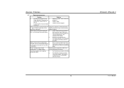
...correct information is extremely important. Set master/slave jumpers correctly. 2. Call the drive manufacturers for compatibility with other drives. 15 TForce4/ TForce4 U User's Manual System only boots from hard disk is securely Power light don't illuminate, fan plugged in ; Hard disk can be read ...system after installing second hard drive. 1. Make sure both ends of breaking down firmly until the module hard drive is spinning. Biostar T-Series 4.3 TROUBLESHOOTING Problem Solution 1. System does not boot from optical drive. 2. Back up the hard drive is in the...
...correct information is extremely important. Set master/slave jumpers correctly. 2. Call the drive manufacturers for compatibility with other drives. 15 TForce4/ TForce4 U User's Manual System only boots from hard disk is securely Power light don't illuminate, fan plugged in ; Hard disk can be read ...system after installing second hard drive. 1. Make sure both ends of breaking down firmly until the module hard drive is spinning. Biostar T-Series 4.3 TROUBLESHOOTING Problem Solution 1. System does not boot from optical drive. 2. Back up the hard drive is in the...

