
TForce4 U user's manual
Page 3
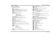
...Graphics slot. Two Ultra DMA 133/100/66/33 IDE connectors. User's Manual Supports AMD Sempron processor. Chipset NVIDIA nForce4 for TForce4 Ultra. NVIDIA nForce4 Ultra for TForce4. Maximum memory space is optional.) 4 USB 2.0 Ports. 6 audio ports support 8 channels audio-out ... 64 /Athlon 64 X2 processors. Supports HyperTransport and AMD Cool'n'Quiet Technology. One CD-ROM audio-in fastest networking performance. Biostar T-Series Chapter 1: Introduction 1.1 MOTHERBOARD FEATURES CPU Supports Socket 939. Note: Does not support Windows 98SE and Windows ME....
...Graphics slot. Two Ultra DMA 133/100/66/33 IDE connectors. User's Manual Supports AMD Sempron processor. Chipset NVIDIA nForce4 for TForce4 Ultra. NVIDIA nForce4 Ultra for TForce4. Maximum memory space is optional.) 4 USB 2.0 Ports. 6 audio ports support 8 channels audio-out ... 64 /Athlon 64 X2 processors. Supports HyperTransport and AMD Cool'n'Quiet Technology. One CD-ROM audio-in fastest networking performance. Biostar T-Series Chapter 1: Introduction 1.1 MOTHERBOARD FEATURES CPU Supports Socket 939. Note: Does not support Windows 98SE and Windows ME....
TForce4 U user's manual
Page 10
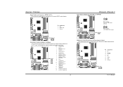
...line-in (optional) Codec BIOS 13 Left line-in (optional) 14 Left line-in (optional) 8 TForce4/ TForce4 U Power Source Header for 1394 Chip: J1394PWR1 3 1 Pin 1-2 Close: +3.3V for 1394 chipset (default). 3 1 J1394PWR1 31 Pin 2-3 Close: +3.3V SB for digital image devices. Codec BIOS ...Header for 1394A Firewire Port at Front Panel: J1394A1 This header allows user to connect the PCI bracket SPDIF output header. Biostar T-Series Digital Audio-out Connector...
...line-in (optional) Codec BIOS 13 Left line-in (optional) 14 Left line-in (optional) 8 TForce4/ TForce4 U Power Source Header for 1394 Chip: J1394PWR1 3 1 Pin 1-2 Close: +3.3V for 1394 chipset (default). 3 1 J1394PWR1 31 Pin 2-3 Close: +3.3V SB for digital image devices. Codec BIOS ...Header for 1394A Firewire Port at Front Panel: J1394A1 This header allows user to connect the PCI bracket SPDIF output header. Biostar T-Series Digital Audio-out Connector...
TForce4 U user's manual
Page 12
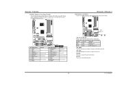
...indicates the system is ready for different messages: LED_D1 LED_D2 Message ON ON Normal ON OFF Memory Error OFF ON VGA Error OFF OFF CPU / Chipset Error LED_DIMM: This LED indicates the voltage of memory is activated normally. Codec Pin Assignment 1 +5V 3 N/A 5 N/A 7 Speaker 9 ... LED, Power LED, Sleep button, speaker and IrDA Connection. TForce4/ TForce4 U LED Indicators and Buttons There are 4 LED indicators on . It allows user to show system status. RSTSW: This is an on diagnostics. Biostar T-Series JPANEL1: Header for Front Panel Facilities This 24-pin ...
...indicates the system is ready for different messages: LED_D1 LED_D2 Message ON ON Normal ON OFF Memory Error OFF ON VGA Error OFF OFF CPU / Chipset Error LED_DIMM: This LED indicates the voltage of memory is activated normally. Codec Pin Assignment 1 +5V 3 N/A 5 N/A 7 Speaker 9 ... LED, Power LED, Sleep button, speaker and IrDA Connection. TForce4/ TForce4 U LED Indicators and Buttons There are 4 LED indicators on . It allows user to show system status. RSTSW: This is an on diagnostics. Biostar T-Series JPANEL1: Header for Front Panel Facilities This 24-pin ...
