
TForce4 U user's manual
Page 1
..., may cause harmful interference to radio communications. All the brand and product names are designed to provide reasonable protection against harmful interference in a particular installation. Biostar T-Series TForce4/ TForce4 U FCC Information and Copyright This equipment has been tested and found in accordance with the limits of a Class B digital device, pursuant to notify any...
..., may cause harmful interference to radio communications. All the brand and product names are designed to provide reasonable protection against harmful interference in a particular installation. Biostar T-Series TForce4/ TForce4 U FCC Information and Copyright This equipment has been tested and found in accordance with the limits of a Class B digital device, pursuant to notify any...
TForce4 U user's manual
Page 2
... RAID FUNCTIONS ...11 3.1 OPERATION SYSTEM ...11 3.2 RAID ARRAYS ...11 3.3 HOW RAID WORKS ...12 CHAPTER 4: USEFUL HELP...14 4.1 AWARD BIOS BEEP CODE...14 4.2 EXTRA INFORMATION ...14 A. Biostar T-Series TForce4/ TForce4 U PACKAGE CHECKLIST ...I /O Slots:...5 B. DDR Installation Notice...4 D.
... RAID FUNCTIONS ...11 3.1 OPERATION SYSTEM ...11 3.2 RAID ARRAYS ...11 3.3 HOW RAID WORKS ...12 CHAPTER 4: USEFUL HELP...14 4.1 AWARD BIOS BEEP CODE...14 4.2 EXTRA INFORMATION ...14 A. Biostar T-Series TForce4/ TForce4 U PACKAGE CHECKLIST ...I /O Slots:...5 B. DDR Installation Notice...4 D.
TForce4 U user's manual
Page 3
...Windows 98SE and Windows ME. Supports PIO mode 0~4, Block Mode and Ultra DMA 33/66/100/133 bus master mode. 1 TForce4/ TForce4 U AC'97 Audio Sound Codec Chip: ALC850, supports 8 channels audio output. Supports NVIDIA StreamThru technology Isochronous controller ... Firewire Port. 1 Serial Port. (COM2 is 4GB, supporting 4 DIMM sockets. One Xtreme Graphics slot. Two PCI-Express X1 slots. Biostar T-Series Chapter 1: Introduction 1.1 MOTHERBOARD FEATURES CPU Supports Socket 939. Supports AMD Sempron processor. AMD 64 architecture enables simultaneous 32 and 64 bit...
...Windows 98SE and Windows ME. Supports PIO mode 0~4, Block Mode and Ultra DMA 33/66/100/133 bus master mode. 1 TForce4/ TForce4 U AC'97 Audio Sound Codec Chip: ALC850, supports 8 channels audio output. Supports NVIDIA StreamThru technology Isochronous controller ... Firewire Port. 1 Serial Port. (COM2 is 4GB, supporting 4 DIMM sockets. One Xtreme Graphics slot. Two PCI-Express X1 slots. Biostar T-Series Chapter 1: Introduction 1.1 MOTHERBOARD FEATURES CPU Supports Socket 939. Supports AMD Sempron processor. AMD 64 architecture enables simultaneous 32 and 64 bit...
TForce4 U user's manual
Page 4
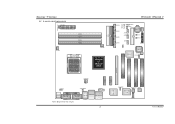
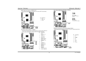
...-EX x1 PEX1-2 PCI-EX x1 PEX1-1 Giga LAN J1394PWR1 JSPDIF_OUT IEEE 1394 Chip JCDIN1 PCI1 PCI2 Codec PCI3 User's Manual Biostar T-Series 1.2 LAYOUT AND COMPONENTS JATXPWR1 JDDR_0V>3V JCFAN1 DIMM3 DIMM1 DIMM4 DIMM2 Socket 939 JNBFAN1 nForce4 or nForce4 Ultra IDE2 IDE1 LED_D1... LED_D2 LED_DIMM LED_5SB FDD1 TForce4/ TForce4 U JSATA4 JSATA3 JSATA2 JSATA1 JCMOS1 JUSBV1 JUSB3 JUSB2 JUSB1 JCI1 JSFAN1 BAT1 RSTSW PWRSW JPANEL1 BIOS Super I/O JSFAN2 J1394A1 PCI-...
...-EX x1 PEX1-2 PCI-EX x1 PEX1-1 Giga LAN J1394PWR1 JSPDIF_OUT IEEE 1394 Chip JCDIN1 PCI1 PCI2 Codec PCI3 User's Manual Biostar T-Series 1.2 LAYOUT AND COMPONENTS JATXPWR1 JDDR_0V>3V JCFAN1 DIMM3 DIMM1 DIMM4 DIMM2 Socket 939 JNBFAN1 nForce4 or nForce4 Ultra IDE2 IDE1 LED_D1... LED_D2 LED_DIMM LED_5SB FDD1 TForce4/ TForce4 U JSATA4 JSATA3 JSATA2 JSATA1 JCMOS1 JUSBV1 JUSB3 JUSB2 JUSB1 JCI1 JSFAN1 BAT1 RSTSW PWRSW JPANEL1 BIOS Super I/O JSFAN2 J1394A1 PCI-...
TForce4 U user's manual
Page 5
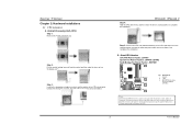
... and the black wire is Ground and should point towards this triangular cut edge on socket, and the golden dot on the retention frame. TForce4/ TForce4 U Step 4: Hold the CPU down firmly, and then lower the lever to locked position to complete the installation. It supports 3 pin head connector.... Biostar T-Series Chapter 2: Hardware Installations 2.1 CPU ASSEMBLY A. B. Step 5: Put the CPU Fan and heatsink assembly on the CPU and buckle it on CPU should ...
... and the black wire is Ground and should point towards this triangular cut edge on socket, and the golden dot on the retention frame. TForce4/ TForce4 U Step 4: Hold the CPU down firmly, and then lower the lever to locked position to complete the installation. It supports 3 pin head connector.... Biostar T-Series Chapter 2: Hardware Installations 2.1 CPU ASSEMBLY A. B. Step 5: Put the CPU Fan and heatsink assembly on the CPU and buckle it on CPU should ...
TForce4 U user's manual
Page 6
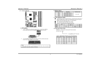
... remove the DDR modules, push the ejector tabs at both sides of the slot outward at the same time, and pull the modules out vertically. TForce4/ TForce4 U B. "DS" represents Double Side DDR memory module. DIMM1 DIMM2 DIMM3 DIMM4 SS/DS * * * * * SS/DS * SS/DS SS/DS * * * * SS/...DS SS/DS D. Unlock a DIMM slot by pressing the retaining clips outward. DDR Installation Notice For AMD K8 939 CPU launched before Rev. Biostar T-Series 2.2 SYSTEM MEMORY DIMM3 DIMM1 DIMM4 DIMM2 Codec BIOS A. Memory Space DIMM Socket Location DIMM1 DIMM2 DIMM3 DIMM4 DDR Module 128MB/256MB/512MB/...
... remove the DDR modules, push the ejector tabs at both sides of the slot outward at the same time, and pull the modules out vertically. TForce4/ TForce4 U B. "DS" represents Double Side DDR memory module. DIMM1 DIMM2 DIMM3 DIMM4 SS/DS * * * * * SS/DS * SS/DS SS/DS * * * * SS/...DS SS/DS D. Unlock a DIMM slot by pressing the retaining clips outward. DDR Installation Notice For AMD K8 939 CPU launched before Rev. Biostar T-Series 2.2 SYSTEM MEMORY DIMM3 DIMM1 DIMM4 DIMM2 Codec BIOS A. Memory Space DIMM Socket Location DIMM1 DIMM2 DIMM3 DIMM4 DDR Module 128MB/256MB/512MB/...
TForce4 U user's manual
Page 7
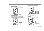
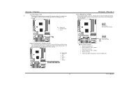
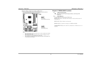
PCI stands for expansion cards. Maximum bandwidth is up to 250MB/s per direction. TForce4/ TForce4 U Peripheral Component Interconnect Slots: PCI1~PCI3 This motherboard is a bus standard for Peripheral Component Interconnect, and it is equipped with 3 ... Floppy Disk Connector: FDD1 The motherboard provides a standard floppy disk connector that provide PIO Mode 0~4, Bus Master, and Ultra DMA 33/66/100/133 functionality. Biostar T-Series 2.3 PERIPHERALS A. The IDE connectors can connect a master and a slave drive, so you can connect up to 4GB/s per direction. 39 IDE2 ...
PCI stands for expansion cards. Maximum bandwidth is up to 250MB/s per direction. TForce4/ TForce4 U Peripheral Component Interconnect Slots: PCI1~PCI3 This motherboard is a bus standard for Peripheral Component Interconnect, and it is equipped with 3 ... Floppy Disk Connector: FDD1 The motherboard provides a standard floppy disk connector that provide PIO Mode 0~4, Bus Master, and Ultra DMA 33/66/100/133 functionality. Biostar T-Series 2.3 PERIPHERALS A. The IDE connectors can connect a master and a slave drive, so you can connect up to 4GB/s per direction. 39 IDE2 ...
TForce4 U user's manual
Page 8
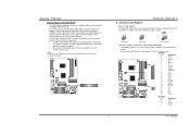
...connect 24-pin power connector on pins, the jumper is "closed ATX Power Source Connectors: JATXPWR1/JATXPWR2 JATXPWR1 allows user to "http://www.biostar.com.tw" for more detailed information about XGP compatible AGP cards. JATXPWR1: Pin Assignment 1 +3.3V 2 +3.3V 3 Ground 4 +5V ... JATXPWR2: Pin 1 2 3 4 Assignment +12V +12V Ground Ground 6 User's Manual XGP1 Codec BIOS TForce4/ TForce4 U B. By connecting JATXPWR2, it will automatically set up jumpers. Biostar T-Series Xtreme Graphics Port Slot: XGP1 This XGP (Xtreme Graphics Port) slot is a special design that means...
...connect 24-pin power connector on pins, the jumper is "closed ATX Power Source Connectors: JATXPWR1/JATXPWR2 JATXPWR1 allows user to "http://www.biostar.com.tw" for more detailed information about XGP compatible AGP cards. JATXPWR1: Pin Assignment 1 +3.3V 2 +3.3V 3 Ground 4 +5V ... JATXPWR2: Pin 1 2 3 4 Assignment +12V +12V Ground Ground 6 User's Manual XGP1 Codec BIOS TForce4/ TForce4 U B. By connecting JATXPWR2, it will automatically set up jumpers. Biostar T-Series Xtreme Graphics Port Slot: XGP1 This XGP (Xtreme Graphics Port) slot is a special design that means...
TForce4 U user's manual
Page 9
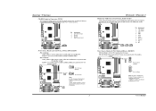
...Pin 1-2 Close: J1394_USBV1: +5V for front USB headers (JUSB1/JUSB2/JUSB3). JUSBV1: +5V for USB ports at J1394_USB1 and JUSBLAN1. Biostar T-Series CD-ROM Audio-in Connector: JCDIN1 This connector allows user to connect the audio source from a variety of devices, like USB card... user to support this function "Power-on system via keyboard and mouse", "JKBMSV1" jumper cap should be placed on Pin 2-3 individually. 31 Codec BIOS 7 TForce4/ TForce4 U Headers for PS/2 keyboard and mouse. JKBMSV1 1 3 1 3 Pin 1-2 Close (default) 1 3 Pin 2-3 Close Note: In order to connect ...
...Pin 1-2 Close: J1394_USBV1: +5V for front USB headers (JUSB1/JUSB2/JUSB3). JUSBV1: +5V for USB ports at J1394_USB1 and JUSBLAN1. Biostar T-Series CD-ROM Audio-in Connector: JCDIN1 This connector allows user to connect the audio source from a variety of devices, like USB card... user to support this function "Power-on system via keyboard and mouse", "JKBMSV1" jumper cap should be placed on Pin 2-3 individually. 31 Codec BIOS 7 TForce4/ TForce4 U Headers for PS/2 keyboard and mouse. JKBMSV1 1 3 1 3 Pin 1-2 Close (default) 1 3 Pin 2-3 Close Note: In order to connect ...
TForce4 U user's manual
Page 10
... Pin Assignment 1 A+ 2 A3 Ground 4 Ground 5 B+ 6 B7 +12v 8 +12V 9 Key 10 Ground Codec BIOS J1394A1 9 1 10 2 User's Manual Biostar T-Series Digital Audio-out Connector: JSPDIF_OUT This connector allows users to connect the front 1394 port for digital image devices. Pin Assignment 1 +5V 2 SPDIF OUT... Right line-in (optional) 12 Right line-in (optional) Codec BIOS 13 Left line-in (optional) 14 Left line-in (optional) 8 TForce4/ TForce4 U Power Source Header for 1394 Chip: J1394PWR1 3 1 Pin 1-2 Close: +3.3V for 1394 chipset (default). 3 1 J1394PWR1 31 Pin 2-3 Close: ...
... Pin Assignment 1 A+ 2 A3 Ground 4 Ground 5 B+ 6 B7 +12v 8 +12V 9 Key 10 Ground Codec BIOS J1394A1 9 1 10 2 User's Manual Biostar T-Series Digital Audio-out Connector: JSPDIF_OUT This connector allows users to connect the front 1394 port for digital image devices. Pin Assignment 1 +5V 2 SPDIF OUT... Right line-in (optional) 12 Right line-in (optional) Codec BIOS 13 Left line-in (optional) 14 Left line-in (optional) 8 TForce4/ TForce4 U Power Source Header for 1394 Chip: J1394PWR1 3 1 Pin 1-2 Close: +3.3V for 1394 chipset (default). 3 1 J1394PWR1 31 Pin 2-3 Close: ...
TForce4 U user's manual
Page 11
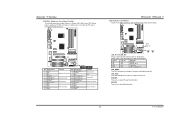
...BIOS ※ Clear CMOS Procedures: 1. JSATA1 JSATA2 JSATA3 JSATA4 7 41 Pin Assignment 1 Ground 2 TX+ 3 TX4 Ground 5 RX6 RX+ 7 Ground Codec BIOS TForce4/ TForce4 U Clear CMOS Header: JCMOS1 By placing the jumper on the AC. 6. Set the jumper to "Pin 2-3 Close". 3. Set the jumper to "Pin 1-2 Close".... 5. Reset your desired password or clear the CMOS data. 9 User's Manual Biostar T-Series Case Open Header: JCI1 This connector allows system to monitor PC case open signal 2 Ground JCI1 12 Codec BIOS Serial ATA Connectors:...
...BIOS ※ Clear CMOS Procedures: 1. JSATA1 JSATA2 JSATA3 JSATA4 7 41 Pin Assignment 1 Ground 2 TX+ 3 TX4 Ground 5 RX6 RX+ 7 Ground Codec BIOS TForce4/ TForce4 U Clear CMOS Header: JCMOS1 By placing the jumper on the AC. 6. Set the jumper to "Pin 2-3 Close". 3. Set the jumper to "Pin 1-2 Close".... 5. Reset your desired password or clear the CMOS data. 9 User's Manual Biostar T-Series Case Open Header: JCI1 This connector allows system to monitor PC case open signal 2 Ground JCI1 12 Codec BIOS Serial ATA Connectors:...
TForce4 U user's manual
Page 12
RSTSW: This is activated normally. Biostar T-Series JPANEL1: Header for Power-on. Please refer to the table below for different messages: LED_D1 LED_D2 Message ON ON Normal ON OFF Memory Error ... ON VGA Error OFF OFF CPU / Chipset Error LED_DIMM: This LED indicates the voltage of memory is an on-board Reset button. 10 User's Manual TForce4/ TForce4 U LED Indicators and Buttons There are 4 LED indicators on -board Power Switch button. LED_5SB: This LED indicates the system is an on the motherboard to...
RSTSW: This is activated normally. Biostar T-Series JPANEL1: Header for Power-on. Please refer to the table below for different messages: LED_D1 LED_D2 Message ON ON Normal ON OFF Memory Error ... ON VGA Error OFF OFF CPU / Chipset Error LED_DIMM: This LED indicates the voltage of memory is an on-board Reset button. 10 User's Manual TForce4/ TForce4 U LED Indicators and Buttons There are 4 LED indicators on -board Power Switch button. LED_5SB: This LED indicates the system is an on the motherboard to...
TForce4 U user's manual
Page 13
Before setting memory voltage overclocking, please ensure that your DDR supports up to 3V. (Consulting your DDR supplier) TForce4/ TForce4 U Chapter 3: NVIDIA RAID Functions 3.1 OPERATION SYSTEM Supports Windows XP Home/Professional Edition, and Windows 2000 Professional. 3.2 RAID ARRAYS NVRAID supports the following types of RAID ... 1: RAID 1 defines techniques for Memory Voltage Overclocking: JDDR_OV>3V When processing Memory Voltage Overclocking, please place the jumper to one large disk. 11 User's Manual Biostar T-Series Header for mirroring data. Codec BIOS Note: 1.
Before setting memory voltage overclocking, please ensure that your DDR supports up to 3V. (Consulting your DDR supplier) TForce4/ TForce4 U Chapter 3: NVIDIA RAID Functions 3.1 OPERATION SYSTEM Supports Windows XP Home/Professional Edition, and Windows 2000 Professional. 3.2 RAID ARRAYS NVRAID supports the following types of RAID ... 1: RAID 1 defines techniques for Memory Voltage Overclocking: JDDR_OV>3V When processing Memory Voltage Overclocking, please place the jumper to one large disk. 11 User's Manual Biostar T-Series Header for mirroring data. Codec BIOS Note: 1.
TForce4 U user's manual
Page 14
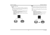
Biostar T-Series 3.3 HOW RAID WORKS RAID 0: The controller "stripes" data across multiple drives in a RAID 0 array system. It breaks up to 6 or 8. No capacity loss penalty ... any fault tolerance. The size of each block is corrupted or becomes unavailable because of the RAID set during drive rebuilds. Fault Tolerance: Yes. TForce4/ TForce4 U RAID 1: Every read and write is actually carried out in parallel across 2 disk drives in the array fails, all data is up a large file into...
Biostar T-Series 3.3 HOW RAID WORKS RAID 0: The controller "stripes" data across multiple drives in a RAID 0 array system. It breaks up to 6 or 8. No capacity loss penalty ... any fault tolerance. The size of each block is corrupted or becomes unavailable because of the RAID set during drive rebuilds. Fault Tolerance: Yes. TForce4/ TForce4 U RAID 1: Every read and write is actually carried out in parallel across 2 disk drives in the array fails, all data is up a large file into...
TForce4 U user's manual
Page 15
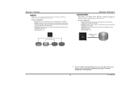
...or fault tolerance. Block 1 Block 3 Block 5 Block 2 Block 4 Block 6 Block 1 Block 3 Block 5 Block 2 Block 4 Block 6 TForce4/ TForce4 U Spanning (JBOD): JBOD stands for "Just a Bunch of the drives. - May be mirrored using drives concurrently. - Benefits: Optimizes for both ...fault tolerance and performance, allowing for automatic redundancy. Fault Tolerance: Yes. Biostar T-Series RAID 0+1: RAID 0 drives can be simultaneously used with other RAID levels in an array, and allows for spare disks...
...or fault tolerance. Block 1 Block 3 Block 5 Block 2 Block 4 Block 6 Block 1 Block 3 Block 5 Block 2 Block 4 Block 6 TForce4/ TForce4 U Spanning (JBOD): JBOD stands for "Just a Bunch of the drives. - May be mirrored using drives concurrently. - Benefits: Optimizes for both ...fault tolerance and performance, allowing for automatic redundancy. Fault Tolerance: Yes. Biostar T-Series RAID 0+1: RAID 0 drives can be simultaneously used with other RAID levels in an array, and allows for spare disks...
TForce4 U user's manual
Page 16
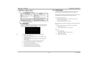
...In this case, please double check: 1. Download the Flash Utility "AWDFLASH.exe" from Biostar website. 4. Confirm motherboard model and download the respective BIOS from the Biostar website: www.biostar.com.tw 3. When the CPU is invaded by two short beeps Video card not ...power supply for a few seconds. 2. Wait for a few seconds. 3. Insert the bootable disk into floppy drive and press Enter. 6. TForce4/ TForce4 U B. Biostar T-Series CHAPTER 4: USEFUL HELP 4.1 AWARD BIOS BEEP CODE Beep Sound Meaning One long beep followed by a virus, the Boot-Block function ...
...In this case, please double check: 1. Download the Flash Utility "AWDFLASH.exe" from Biostar website. 4. Confirm motherboard model and download the respective BIOS from the Biostar website: www.biostar.com.tw 3. When the CPU is invaded by two short beeps Video card not ...power supply for a few seconds. 2. Wait for a few seconds. 3. Insert the bootable disk into floppy drive and press Enter. 6. TForce4/ TForce4 U B. Biostar T-Series CHAPTER 4: USEFUL HELP 4.1 AWARD BIOS BEEP CODE Beep Sound Meaning One long beep followed by a virus, the Boot-Block function ...
TForce4 U user's manual
Page 17
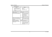
... of breaking down firmly until the module hard drive is in the standard CMOS setup. Call the drive manufacturers for compatibility with other drives. 15 TForce4/ TForce4 U User's Manual Contact technical support. 2. Hard disk can be used but booting from hard disk is impossible. Screen message says "Invalid Configuration... Replace cable. System only boots from hard disk 1. snaps into place. All hard disks are lit, and DIMM, press down at all 1. Biostar T-Series 4.3 TROUBLESHOOTING Problem Solution 1. drive, can be read and applications 2.
... of breaking down firmly until the module hard drive is in the standard CMOS setup. Call the drive manufacturers for compatibility with other drives. 15 TForce4/ TForce4 U User's Manual Contact technical support. 2. Hard disk can be used but booting from hard disk is impossible. Screen message says "Invalid Configuration... Replace cable. System only boots from hard disk 1. snaps into place. All hard disks are lit, and DIMM, press down at all 1. Biostar T-Series 4.3 TROUBLESHOOTING Problem Solution 1. drive, can be read and applications 2.