
TForce4 U user's manual
Page 3
...specification, with transfer up to 400Mb/s. Supports PIO mode 0~4, Block Mode and Ultra DMA 33/66/100/133 bus master mode. 1 TForce4/ TForce4 U AC'97 Audio Sound Codec Chip: ALC850, supports 8 channels audio output. IEEE 1394A Chip Chip: VIA VT6307, supports 2 ports ...Maximum memory space is optional.) 4 USB 2.0 Ports. 6 audio ports support 8 channels audio-out facilities. User's Manual Biostar T-Series Chapter 1: Introduction 1.1 MOTHERBOARD FEATURES CPU Supports Socket 939. Dimensions ATX Form Factor: 23.4cm (W) x 29.35cm (L) Main Memory Supports Dual Channel DDR. Supports DDR333 and...
...specification, with transfer up to 400Mb/s. Supports PIO mode 0~4, Block Mode and Ultra DMA 33/66/100/133 bus master mode. 1 TForce4/ TForce4 U AC'97 Audio Sound Codec Chip: ALC850, supports 8 channels audio output. IEEE 1394A Chip Chip: VIA VT6307, supports 2 ports ...Maximum memory space is optional.) 4 USB 2.0 Ports. 6 audio ports support 8 channels audio-out facilities. User's Manual Biostar T-Series Chapter 1: Introduction 1.1 MOTHERBOARD FEATURES CPU Supports Socket 939. Dimensions ATX Form Factor: 23.4cm (W) x 29.35cm (L) Main Memory Supports Dual Channel DDR. Supports DDR333 and...
TForce4 U user's manual
Page 4
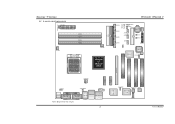
... LAN J1394PWR1 JSPDIF_OUT IEEE 1394 Chip JCDIN1 PCI1 PCI2 Codec PCI3 User's Manual Biostar T-Series 1.2 LAYOUT AND COMPONENTS JATXPWR1 JDDR_0V>3V JCFAN1 DIMM3 DIMM1 DIMM4 DIMM2 Socket 939 JNBFAN1 nForce4 or nForce4 Ultra IDE2 IDE1 LED_D1 LED_D2 LED_DIMM LED_5SB FDD1 TForce4/ TForce4 U JSATA4 JSATA3 JSATA2 JSATA1 JCMOS1 JUSBV1 JUSB3 JUSB2 JUSB1 JCI1 JSFAN1 BAT1...
... LAN J1394PWR1 JSPDIF_OUT IEEE 1394 Chip JCDIN1 PCI1 PCI2 Codec PCI3 User's Manual Biostar T-Series 1.2 LAYOUT AND COMPONENTS JATXPWR1 JDDR_0V>3V JCFAN1 DIMM3 DIMM1 DIMM4 DIMM2 Socket 939 JNBFAN1 nForce4 or nForce4 Ultra IDE2 IDE1 LED_D1 LED_D2 LED_DIMM LED_5SB FDD1 TForce4/ TForce4 U JSATA4 JSATA3 JSATA2 JSATA1 JCMOS1 JUSBV1 JUSB3 JUSB2 JUSB1 JCI1 JSFAN1 BAT1...
TForce4 U user's manual
Page 6
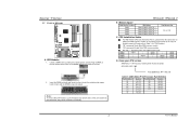
...Manual Unlock a DIMM slot by pressing the retaining clips outward. DDR Installation Notice For AMD K8 939 CPU launched before Rev. E, please follow the table below to Table 1 for CPU Revision) "...DIMM on the slot such that the notch on the DIMM matches the break on the slot. 2. TForce4/ TForce4 U B. C. Insert the DIMM vertically and firmly into the slot until the retaining chip snaps back... SS/DS SS/DS SS/DS SS/DS D. Star sign "*" represents leave the DIMM socket empty. Biostar T-Series 2.2 SYSTEM MEMORY DIMM3 DIMM1 DIMM4 DIMM2 Codec BIOS A. Notes: To remove the DDR modules, ...
...Manual Unlock a DIMM slot by pressing the retaining clips outward. DDR Installation Notice For AMD K8 939 CPU launched before Rev. E, please follow the table below to Table 1 for CPU Revision) "...DIMM on the slot such that the notch on the DIMM matches the break on the slot. 2. TForce4/ TForce4 U B. C. Insert the DIMM vertically and firmly into the slot until the retaining chip snaps back... SS/DS SS/DS SS/DS SS/DS D. Star sign "*" represents leave the DIMM socket empty. Biostar T-Series 2.2 SYSTEM MEMORY DIMM3 DIMM1 DIMM4 DIMM2 Codec BIOS A. Notes: To remove the DDR modules, ...
