
Setup Manual
Page 1
... right to be responsible for any party beforehand. Duplication of this publication, in part or in whole, is subject to revise this user's manual is not allowed without obligation to radio communications. These limits are trademarks of the FCC Rules. The content of merchantability or fitness for any...obtaining the vendor's approval in writing. There is no representations or warranties with the instructions, may cause harmful interference to notify any purpose. T5 XE/T5XE CFX-SLI Setup Manual FCC Information and Copyright This equipment has been tested and found in this user...
... right to be responsible for any party beforehand. Duplication of this publication, in part or in whole, is subject to revise this user's manual is not allowed without obligation to radio communications. These limits are trademarks of the FCC Rules. The content of merchantability or fitness for any...obtaining the vendor's approval in writing. There is no representations or warranties with the instructions, may cause harmful interference to notify any purpose. T5 XE/T5XE CFX-SLI Setup Manual FCC Information and Copyright This equipment has been tested and found in this user...
Setup Manual
Page 3
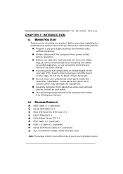
... and stable working environment with sufficient lighting. „ Always disconnect the computer from power outlet before operation. „ Before you for ATX Case X 1 User's Manual X 1 Fully Setup Driver CD X 1 FDD Cable X 1 (optional) USB 2.0 Cable X1 (optional) Serial ATA Power Cable X 1 (optional) SLI /... Celsius. 1.2 PACKAGE CHECKLIST HDD Cable X 1 (optional) Serial ATA Cable X 3 Rear I/O Panel for choosing our product. CHAPTER 1: INTRODUCTION T5 XE/T5XE CFX-SLI 1.1 BEFORE YOU START Thank you take the motherboard out from dangerous area, such as heat source, humid air and water. &#...
... and stable working environment with sufficient lighting. „ Always disconnect the computer from power outlet before operation. „ Before you for ATX Case X 1 User's Manual X 1 Fully Setup Driver CD X 1 FDD Cable X 1 (optional) USB 2.0 Cable X1 (optional) Serial ATA Power Cable X 1 (optional) SLI /... Celsius. 1.2 PACKAGE CHECKLIST HDD Cable X 1 (optional) Serial ATA Cable X 3 Rear I/O Panel for choosing our product. CHAPTER 1: INTRODUCTION T5 XE/T5XE CFX-SLI 1.1 BEFORE YOU START Thank you take the motherboard out from dangerous area, such as heat source, humid air and water. &#...
Setup Manual
Page 4
... Board IDE Connector Connectors SATA Connector x1 Each connector supports 2 Floppy drives x1 Each connector supports 2 IDE device x6 Each connector supports 1 SATA devices 2 Motherboard Manual 1.3 MOTHERBOARD FEATURES SPEC Supports Execute Disable Bit / Enhanced Intel Socket 1156 CPU Intel Core i7 / i5 processor SpeedStep® / Intel Architecture-64 / Extended Memory 64...
... Board IDE Connector Connectors SATA Connector x1 Each connector supports 2 Floppy drives x1 Each connector supports 2 IDE device x6 Each connector supports 1 SATA devices 2 Motherboard Manual 1.3 MOTHERBOARD FEATURES SPEC Supports Execute Disable Bit / Enhanced Intel Socket 1156 CPU Intel Core i7 / i5 processor SpeedStep® / Intel Architecture-64 / Extended Memory 64...

Setup Manual
Page 6
PH 4 _D4 PH 4 _D3 PH 4 _D2 PH 4 _D1 VTT _D2 DDR3 _A 2 DDR3 _A 1 DDR3 _B 2 DDR3 _B 1 Motherboard Manual 1.5 MOTHERBOARD LAYOUT JUSBV1 KBMS1 USB2 USB1 ATXPWR2 VTT_D1 CPU_FAN1 Socket 1156 CPU1 RJ45USB1 AUDIO2 SPDIF1 CD_IN1 SYS_FAN2 LAN PEX16_1 ATXPWR1 BIOS IDE 1 Super I/O PEX1_1 PEX1_2 PEX16_2 P55 IDE PCI1 BAT1 SATA6 SATA5 SATA4 SATA3 SATA2 SATA1 CODEC F_AUDIO1 PCI2 FDD1 JUSBV2 JCMOS1 SYS_ FAN1 LED2 LE D1 SW_ PWR F_COM 1 F_USB2 F_USB1 SW_ RST PANEL1 Note: ■ represents the 1st pin. 4
PH 4 _D4 PH 4 _D3 PH 4 _D2 PH 4 _D1 VTT _D2 DDR3 _A 2 DDR3 _A 1 DDR3 _B 2 DDR3 _B 1 Motherboard Manual 1.5 MOTHERBOARD LAYOUT JUSBV1 KBMS1 USB2 USB1 ATXPWR2 VTT_D1 CPU_FAN1 Socket 1156 CPU1 RJ45USB1 AUDIO2 SPDIF1 CD_IN1 SYS_FAN2 LAN PEX16_1 ATXPWR1 BIOS IDE 1 Super I/O PEX1_1 PEX1_2 PEX16_2 P55 IDE PCI1 BAT1 SATA6 SATA5 SATA4 SATA3 SATA2 SATA1 CODEC F_AUDIO1 PCI2 FDD1 JUSBV2 JCMOS1 SYS_ FAN1 LED2 LE D1 SW_ PWR F_COM 1 F_USB2 F_USB1 SW_ RST PANEL1 Note: ■ represents the 1st pin. 4

Setup Manual
Page 8
Step 5: Put the CPU Fan and heatsink assembly on the CPU and buckle it on CPU should point forwards this triangular cut edge. Connect the CPU FAN power cable into the CPU_FAN1 to complete the installation. Step 4: Hold the CPU down firmly, and then lower the lever to locked position to complete the installation. 6 The CPU will fit only in the correct orientation. Motherboard Manual Step 3: Look for the triangular cut edge on socket, and the golden dot on the retention frame.
Step 5: Put the CPU Fan and heatsink assembly on the CPU and buckle it on CPU should point forwards this triangular cut edge. Connect the CPU FAN power cable into the CPU_FAN1 to complete the installation. Step 4: Hold the CPU down firmly, and then lower the lever to locked position to complete the installation. 6 The CPU will fit only in the correct orientation. Motherboard Manual Step 3: Look for the triangular cut edge on socket, and the golden dot on the retention frame.

Setup Manual
Page 10
Align a DIMM on the slot such that the notch on the DIMM matches the break on the Slot. 2. DDR3_A2 DDR3_A1 DDR3_B2 DDR3_B1 Motherboard Manual 2.3 INSTALLING SYSTEM MEMORY A. Insert the DIMM vertically and firmly into the slot until the retaining chip snap back in place and the DIMM is properly seated. 8 Memory Modules 1. Unlock a DIMM slot by pressing the retaining clips outward.
Align a DIMM on the slot such that the notch on the DIMM matches the break on the Slot. 2. DDR3_A2 DDR3_A1 DDR3_B2 DDR3_B1 Motherboard Manual 2.3 INSTALLING SYSTEM MEMORY A. Insert the DIMM vertically and firmly into the slot until the retaining chip snap back in place and the DIMM is properly seated. 8 Memory Modules 1. Unlock a DIMM slot by pressing the retaining clips outward.

Setup Manual
Page 12
This connector supports the provided floppy drive ribbon cables. 2 34 1 33 IDE1: Hard Disk Connector The motherboard has a 32-bit Enhanced PCI IDE Controller that supports 360K, 720K, 1.2M, 1.44M and 2.88M floppy disk types. The IDE connector can connect a master and a slave drive, so you can connect up to two hard disk drives. 12 39 40 10 Motherboard Manual 2.4 CONNECTORS AND SLOTS FDD1: Floppy Disk Connector The motherboard provides a standard floppy disk connector that provides PIO Mode 0~4, Bus Master, and Ultra DMA 33/66/100/133 functionality.
This connector supports the provided floppy drive ribbon cables. 2 34 1 33 IDE1: Hard Disk Connector The motherboard has a 32-bit Enhanced PCI IDE Controller that supports 360K, 720K, 1.2M, 1.44M and 2.88M floppy disk types. The IDE connector can connect a master and a slave drive, so you can connect up to two hard disk drives. 12 39 40 10 Motherboard Manual 2.4 CONNECTORS AND SLOTS FDD1: Floppy Disk Connector The motherboard provides a standard floppy disk connector that provides PIO Mode 0~4, Bus Master, and Ultra DMA 33/66/100/133 functionality.

Setup Manual
Page 14
PCI stands for expansion cards. PCI1/PCI2: Peripheral Component Interconnect Slots This motherboard is a bus standard for Peripheral Component Interconnect, and it is equipped with 2 standard PCI slots. PC I1 PCI2 12 Motherboard Manual ATXPWR2: ATX Power Source Connector This connector provides +12V to CPU power circuit. 32 4 1 Pin Assignment 1 +12V 2 +12V 3 Ground 4 Ground Note: Before you power on the system, please make sure that both ATXPWR1 and ATXPWR2 connectors have been well plugged-in. This PCI slot is designated as 32 bits.
PCI stands for expansion cards. PCI1/PCI2: Peripheral Component Interconnect Slots This motherboard is a bus standard for Peripheral Component Interconnect, and it is equipped with 2 standard PCI slots. PC I1 PCI2 12 Motherboard Manual ATXPWR2: ATX Power Source Connector This connector provides +12V to CPU power circuit. 32 4 1 Pin Assignment 1 +12V 2 +12V 3 Ground 4 Ground Note: Before you power on the system, please make sure that both ATXPWR1 and ATXPWR2 connectors have been well plugged-in. This PCI slot is designated as 32 bits.
Setup Manual
Page 16
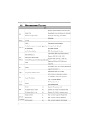
... opened Pin closed Pin1-2 closed 3.2 DETAIL SETTINGS PANEL1: Front Panel Header This 16-pin connector includes Power-on button 14 POW_LED On/Off ++- 9 16 1 8 +- Motherboard Manual CHAPTER 3: HEADERS & JUMPERS SETUP 3.1 HOW TO SETUP JUMPERS The illustration shows how to connect the PC case's front panel switch functions. SPK RST HLED Pin...
... opened Pin closed Pin1-2 closed 3.2 DETAIL SETTINGS PANEL1: Front Panel Header This 16-pin connector includes Power-on button 14 POW_LED On/Off ++- 9 16 1 8 +- Motherboard Manual CHAPTER 3: HEADERS & JUMPERS SETUP 3.1 HOW TO SETUP JUMPERS The illustration shows how to connect the PC case's front panel switch functions. SPK RST HLED Pin...

Setup Manual
Page 18
... connector allows user to connect the front audio output cable with the PC front panel. This header allows only HD audio front panel connector; Motherboard Manual F_AUDIO1: Front Panel Audio Header This header allows user to connect the PCI bracket SPDIF output header. AC'97 connector is not acceptable. 2 10 Pin...
... connector allows user to connect the front audio output cable with the PC front panel. This header allows only HD audio front panel connector; Motherboard Manual F_AUDIO1: Front Panel Audio Header This header allows user to connect the PCI bracket SPDIF output header. AC'97 connector is not acceptable. 2 10 Pin...

Setup Manual
Page 20
... LED2 Message ON ON Normal ON OFF OFF Memory Error ON VGA Error OFF OFF Abnormal: CPU / Chipset error. SW_RST SW_PWR SW_RST1: Reset button. Motherboard Manual On-Board LED Indicators There are 2 on the motherboard showing system status. PH1_D1 ~ PH4_D4 VTT_D1 ~ VTT_D2 ON OFF Phase Indicator Phase Active Phase Inactive On...
... LED2 Message ON ON Normal ON OFF OFF Memory Error ON VGA Error OFF OFF Abnormal: CPU / Chipset error. SW_RST SW_PWR SW_RST1: Reset button. Motherboard Manual On-Board LED Indicators There are 2 on the motherboard showing system status. PH1_D1 ~ PH4_D4 VTT_D1 ~ VTT_D2 ON OFF Phase Indicator Phase Active Phase Inactive On...

Setup Manual
Page 21
T5 XE/T5XE CFX-SLI CHAPTER 4: T-SERIES BIOS & SOFTWARE 4.1 T-SERIES BIOS T-Series BIOS Features Overclocking Navigator Engine (O.N.E.) Memory Integration Test (M.I.T., under Overclock Navigator Engine) BIO-Flasher: Update BIOS file from this manual is being continuously updated. For ... no display after overclocking Over-Clocking Navigator [Normal] =========== Automate OverClock System =========== Auto OverClock System [V6-Tech Engine] Manual OverClock System Current CPU Frequency : Current Memory Frequency : Over Clock Retry Count [1] Intel(R) SpeedStep(tm) tech [Enabled...
T5 XE/T5XE CFX-SLI CHAPTER 4: T-SERIES BIOS & SOFTWARE 4.1 T-SERIES BIOS T-Series BIOS Features Overclocking Navigator Engine (O.N.E.) Memory Integration Test (M.I.T., under Overclock Navigator Engine) BIO-Flasher: Update BIOS file from this manual is being continuously updated. For ... no display after overclocking Over-Clocking Navigator [Normal] =========== Automate OverClock System =========== Auto OverClock System [V6-Tech Engine] Manual OverClock System Current CPU Frequency : Current Memory Frequency : Over Clock Retry Count [1] Intel(R) SpeedStep(tm) tech [Enabled...

Setup Manual
Page 22
...display after overclocking Over-Clocking Navigator [Normal] =========== Automate OverClock System =========== Auto OverClock System [V6-Tech Engine] Manual OverClock System Current CPU Frequency :Options Current Memory Frequency Norm:al Over Clock Retry Count Auto[m1a]te OverClock ... [Auto] > DRAM Timing Configuration > Clock Gen Configuration > Voltage Control > Intel PPM Configuration Options Normal Automate OverClock Manual OverClock Select Screen Select Item EnterGo to enable SpeedStep technology for experienced overclock users. Intel(R) SpeedStep(tm) Tech This item...
...display after overclocking Over-Clocking Navigator [Normal] =========== Automate OverClock System =========== Auto OverClock System [V6-Tech Engine] Manual OverClock System Current CPU Frequency :Options Current Memory Frequency Norm:al Over Clock Retry Count Auto[m1a]te OverClock ... [Auto] > DRAM Timing Configuration > Clock Gen Configuration > Voltage Control > Intel PPM Configuration Options Normal Automate OverClock Manual OverClock Select Screen Select Item EnterGo to enable SpeedStep technology for experienced overclock users. Intel(R) SpeedStep(tm) Tech This item...
Setup Manual
Page 23
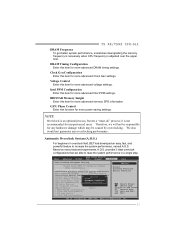
...not a "must-do" process; Based on many tests and experiments, A.O.S. T5 XE/T5XE CFX-SLI DRAM Frequency To get better system performance, sometimes downgrading the memory...caused by overclocking. DRAM Timing Configuration Enter this item for inexperienced users. BIOSTAR Me mory Insight Enter this item for more advanced Intel PPM settings. ...Configuration > Clock Gen Configuration > Voltage Control > Intel PPM Configuration Options Normal Automate OverClock Manual OverClock Select Screen Select Item EnterGo to increase the system performance, named A.O.S. Intel PPM ...
...not a "must-do" process; Based on many tests and experiments, A.O.S. T5 XE/T5XE CFX-SLI DRAM Frequency To get better system performance, sometimes downgrading the memory...caused by overclocking. DRAM Timing Configuration Enter this item for inexperienced users. BIOSTAR Me mory Insight Enter this item for more advanced Intel PPM settings. ...Configuration > Clock Gen Configuration > Voltage Control > Intel PPM Configuration Options Normal Automate OverClock Manual OverClock Select Screen Select Item EnterGo to increase the system performance, named A.O.S. Intel PPM ...

Setup Manual
Page 24
..., Inc. Over-Clocking Navigator [Automate OverClock] =========== Automate OverClock System =========== Auto OverClock System [V8-Tech Engine] Manual OverClock System Current CPU Frequency : Current Memory Frequency : Over Clock Retry Count [1] Intel(R) SpeedStep(tm) tech ...after overclocking. Over-Clocking Navigator [Automate OverClock] =========== Automate OverClock System =========== Auto OverClock System [V12-Tech Engine] Manual OverClock System Current CPU Frequency : Current Memory Frequency : Over Clock Retry Count [1] Intel(R) SpeedStep(tm) tech...
..., Inc. Over-Clocking Navigator [Automate OverClock] =========== Automate OverClock System =========== Auto OverClock System [V8-Tech Engine] Manual OverClock System Current CPU Frequency : Current Memory Frequency : Over Clock Retry Count [1] Intel(R) SpeedStep(tm) tech ...after overclocking. Over-Clocking Navigator [Automate OverClock] =========== Automate OverClock System =========== Auto OverClock System [V12-Tech Engine] Manual OverClock System Current CPU Frequency : Current Memory Frequency : Over Clock Retry Count [1] Intel(R) SpeedStep(tm) tech...

Setup Manual
Page 25
... Navigator [Normal] =========== Automate OverClock System =========== Auto OverClock System [V6-Tech Engine] Manual OverClock System Current CPU Frequency : Current Memory Frequency : Over Clock Retry Count [1] ... DRAM Timing Configuration > Clock Gen Configuration > Voltage Control > Intel PPM Configuration > BIOSTAR Memory Insight > G.P.U Phase Control Integrated Memory Test [Enabled] Options HotKey F11 Disabled ... B. Step 1 The default setting under "Overclocking Navigator Engine" item. T5 XE/T5XE CFX-SLI Notices: Not all types of Intel CPU perform above ...
... Navigator [Normal] =========== Automate OverClock System =========== Auto OverClock System [V6-Tech Engine] Manual OverClock System Current CPU Frequency : Current Memory Frequency : Over Clock Retry Count [1] ... DRAM Timing Configuration > Clock Gen Configuration > Voltage Control > Intel PPM Configuration > BIOSTAR Memory Insight > G.P.U Phase Control Integrated Memory Test [Enabled] Options HotKey F11 Disabled ... B. Step 1 The default setting under "Overclocking Navigator Engine" item. T5 XE/T5XE CFX-SLI Notices: Not all types of Intel CPU perform above ...

Setup Manual
Page 26
... device with BIO-Flasher 1. Insert the USB pen drive or the floppy disk that contains the BIOS file to perform the BIOS update process. 6. Motherboard Manual C. To enter the utility, press during the POST process. Power on the right appears. Press to reboot the system. The BIO-Flasher is a BIOS flashing...
... device with BIO-Flasher 1. Insert the USB pen drive or the floppy disk that contains the BIOS file to perform the BIOS update process. 6. Motherboard Manual C. To enter the utility, press during the POST process. Power on the right appears. Press to reboot the system. The BIO-Flasher is a BIOS flashing...

Setup Manual
Page 28
... Backup Func CMOS Data Reload CMOS Data Save O.N.E Exit Select Screen Select Item EnterGo to reload any saved CMOS setting for customizing system configurations. Motherboard Manual Smart Fan Calibration Choose this set value, the CPU/ System fan will turn off. Fan Ctrl OFF(℃) If the CPU/System temperature is from...
... Backup Func CMOS Data Reload CMOS Data Save O.N.E Exit Select Screen Select Item EnterGo to reload any saved CMOS setting for customizing system configurations. Motherboard Manual Smart Fan Calibration Choose this set value, the CPU/ System fan will turn off. Fan Ctrl OFF(℃) If the CPU/System temperature is from...

Setup Manual
Page 30
The Memory tab provides information on the CPU and motherboard. It also provides six pre-set modes for you to see its information. Motherboard Manual The CPU tab provides information on the memory module(s). The OC Tweaker tab allows you : 28 You can select memory module on a specific slot to change system clock settings and voltages settings.
The Memory tab provides information on the CPU and motherboard. It also provides six pre-set modes for you to see its information. Motherboard Manual The CPU tab provides information on the memory module(s). The OC Tweaker tab allows you : 28 You can select memory module on a specific slot to change system clock settings and voltages settings.

Setup Manual
Page 32
moreover, it optimizes power saving and best power efficiency on light loading. The utility enhances energy efficiency by disabling extra phases while CPU is a new function. It integrates a friendly GUI to monitor your system. 30 Motherboard Manual Green Power Utility BIOSTAR G.P.U (Green Power Utility) is on your CPU Usage, CPU Watt, and CPU Temperature;
moreover, it optimizes power saving and best power efficiency on light loading. The utility enhances energy efficiency by disabling extra phases while CPU is a new function. It integrates a friendly GUI to monitor your system. 30 Motherboard Manual Green Power Utility BIOSTAR G.P.U (Green Power Utility) is on your CPU Usage, CPU Watt, and CPU Temperature;

