Setup Manual
Page 2
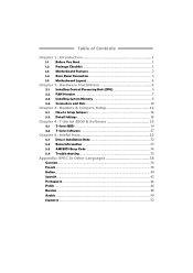
Table of Contents Chapter 1: Introduction 1 1.1 Before You Start 1 1.2 Package Checklist 1 1.3 Motherboard Features 2 1.4 Rear Panel Connectors 3 1.5 Motherboard Layout 4 Chapter 2: Hardware Installation 5 2.1 Installing Central Processing Unit (CPU 5 2.2 FAN Headers 7 2.3 Installing System Memory 8 2.4 Connectors and Slots 10 Chapter 3: Headers & Jumpers Setup 14 3.1 How to ...
Table of Contents Chapter 1: Introduction 1 1.1 Before You Start 1 1.2 Package Checklist 1 1.3 Motherboard Features 2 1.4 Rear Panel Connectors 3 1.5 Motherboard Layout 4 Chapter 2: Hardware Installation 5 2.1 Installing Central Processing Unit (CPU 5 2.2 FAN Headers 7 2.3 Installing System Memory 8 2.4 Connectors and Slots 10 Chapter 3: Headers & Jumpers Setup 14 3.1 How to ...
Setup Manual
Page 3
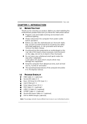
... board. „ Do not leave any unfastened small parts inside the case after installation. CHAPTER 1: INTRODUCTION T41 HD 1.1 BEFORE YOU START Thank you take the motherboard out from anti-static bag, ground yourself properly by touching any safely grounded appliance, or use grounded wrist ...remove the static charge. „ Avoid touching the components on the edge, do not try to area or your motherboard version. 1 Before you start installing the motherboard, please make sure you follow the instructions below: „ Prepare a dry and stable working environment with sufficient lighting....
... board. „ Do not leave any unfastened small parts inside the case after installation. CHAPTER 1: INTRODUCTION T41 HD 1.1 BEFORE YOU START Thank you take the motherboard out from anti-static bag, ground yourself properly by touching any safely grounded appliance, or use grounded wrist ...remove the static charge. „ Avoid touching the components on the edge, do not try to area or your motherboard version. 1 Before you start installing the motherboard, please make sure you follow the instructions below: „ Prepare a dry and stable working environment with sufficient lighting....
Setup Manual
Page 4
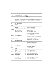
... SATA Connector x4 Each connector supports 1 SATA devices Front Panel Connector x1 Supports front panel facilities Front Audio Connector x1 Supports front panel audio function 2 Motherboard Manual 1.3 MOTHERBOARD FEATURES SPEC LGA 775 Supports Hyper-Threading / Execute Disable Bit / Intel Core2Duo / Core2Quad / Celeron 4xx Enhanced Intel SpeedStep® / Intel Architecture-64 / CPU / Pentium...
... SATA Connector x4 Each connector supports 1 SATA devices Front Panel Connector x1 Supports front panel facilities Front Audio Connector x1 Supports front panel audio function 2 Motherboard Manual 1.3 MOTHERBOARD FEATURES SPEC LGA 775 Supports Hyper-Threading / Execute Disable Bit / Intel Core2Duo / Core2Quad / Celeron 4xx Enhanced Intel SpeedStep® / Intel Architecture-64 / CPU / Pentium...
Setup Manual
Page 6
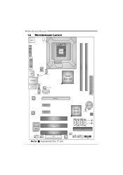
P H4 PH 3 P H2 PH 1 Motherboard Manual 1.5 MOTHERBOARD LAYOUT KBMS1 LGA775 CPU1 V GA 1 DV I1 D DR2_A1 D DR2_B1 USB1 ATXPWR2 CPU_FAN1 JUSBV1 RJ45USB1 CD_ I N1 AUDIO1 SYS_FAN1 Intel G41 A3 SPDIF1 AUXPWR1 LAN PEX16_1 ATXPWR1 CODEC PEX1_1 PEX1_2 Intel ICH7 BAT1 JCMO S1 BI O S PCI1 SATA1 SATA3 SW _RST1 Super PCI2 I/O SATA2 SW _PW R1 SATA4 IDE1 PCI3 JUSBV2 F_AUDIO1 F_COM1 FDD1 SYS_FAN2 F_USB1 F_USB2 LED2 L ED1 PANEL1 Note: ■ represents the 1st pin. 4
P H4 PH 3 P H2 PH 1 Motherboard Manual 1.5 MOTHERBOARD LAYOUT KBMS1 LGA775 CPU1 V GA 1 DV I1 D DR2_A1 D DR2_B1 USB1 ATXPWR2 CPU_FAN1 JUSBV1 RJ45USB1 CD_ I N1 AUDIO1 SYS_FAN1 Intel G41 A3 SPDIF1 AUXPWR1 LAN PEX16_1 ATXPWR1 CODEC PEX1_1 PEX1_2 Intel ICH7 BAT1 JCMO S1 BI O S PCI1 SATA1 SATA3 SW _RST1 Super PCI2 I/O SATA2 SW _PW R1 SATA4 IDE1 PCI3 JUSBV2 F_AUDIO1 F_COM1 FDD1 SYS_FAN2 F_USB1 F_USB2 LED2 L ED1 PANEL1 Note: ■ represents the 1st pin. 4
Setup Manual
Page 8
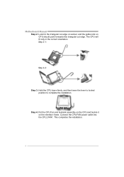
Connect the CPU FAN power cable into the CPU_FAN1. Motherboard Manual Step 2: Look for the triangular cut edge on socket, and the golden dot on the retention frame. Step 4: Put the CPU Fan and heatsink assembly on the CPU and buckle it on CPU should point forwards this triangular cut edge. This completes the installation. 6 Step 2-1: Step 2-2: Step 3: Hold the CPU down firmly, and then lower the lever to locked position to complete the installation. The CPU will fit only in the correct orientation.
Connect the CPU FAN power cable into the CPU_FAN1. Motherboard Manual Step 2: Look for the triangular cut edge on socket, and the golden dot on the retention frame. Step 4: Put the CPU Fan and heatsink assembly on the CPU and buckle it on CPU should point forwards this triangular cut edge. This completes the installation. 6 Step 2-1: Step 2-2: Step 3: Hold the CPU down firmly, and then lower the lever to locked position to complete the installation. The CPU will fit only in the correct orientation.
Setup Manual
Page 10
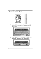
Unlock a DIMM slot by pressing the retaining clips outward. Align a DIMM on the slot such that the notch on the DIMM matches the break on the Slot. 2. Memory Modules 1. Insert the DIMM vertically and firmly into the slot until the retaining chip snap back in place and the DIMM is properly seated. 8 DDR2_A1 DDR2_B1 Motherboard Manual 2.3 INSTALLING SYSTEM MEMORY A.
Unlock a DIMM slot by pressing the retaining clips outward. Align a DIMM on the slot such that the notch on the DIMM matches the break on the Slot. 2. Memory Modules 1. Insert the DIMM vertically and firmly into the slot until the retaining chip snap back in place and the DIMM is properly seated. 8 DDR2_A1 DDR2_B1 Motherboard Manual 2.3 INSTALLING SYSTEM MEMORY A.
Setup Manual
Page 12
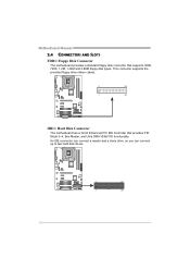
This connector supports the provided floppy drive ribbon cables. 2 34 1 33 IDE1: Hard Disk Connector The motherboard has a 32-bit Enhanced PCI IDE Controller that supports 360K, 720K, 1.2M, 1.44M and 2.88M floppy disk types. An IDE connector can connect a master and a slave drive, so you can connect up to two hard disk drives. 2 40 1 39 10 Motherboard Manual 2.4 CONNECTORS AND SLOTS FDD1: Floppy Disk Connector The motherboard provides a standard floppy disk connector that provides PIO Mode 0~4, Bus Master, and Ultra DMA 33/66/100 functionality.
This connector supports the provided floppy drive ribbon cables. 2 34 1 33 IDE1: Hard Disk Connector The motherboard has a 32-bit Enhanced PCI IDE Controller that supports 360K, 720K, 1.2M, 1.44M and 2.88M floppy disk types. An IDE connector can connect a master and a slave drive, so you can connect up to two hard disk drives. 2 40 1 39 10 Motherboard Manual 2.4 CONNECTORS AND SLOTS FDD1: Floppy Disk Connector The motherboard provides a standard floppy disk connector that provides PIO Mode 0~4, Bus Master, and Ultra DMA 33/66/100 functionality.
Setup Manual
Page 13
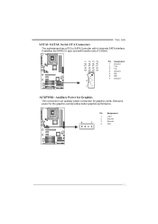
SATA 1 SATA 2 SATA 3 SATA 4 Pin Assignment 1 Ground 2 TX+ 3 TX- 4 Ground 1 5 RX6 RX+ 7 Ground 4 7 AUXPWR1: Auxiliary Power for Graphics This connector is an auxiliary power connection for the graphics card provides better graphics performance. Pin Assignment 1 +12V 2 Ground 4 1 3 Ground 4 VCC 11 It satisfies the SATA 2.0 spec and with 4 channels SATA interface. Exclusive power for graphics cards. T41 HD SATA1~SATA4: Serial ATA Connectors The motherboard has a PCI to SATA Controller with transfer rate of 3.0Gb/s.
SATA 1 SATA 2 SATA 3 SATA 4 Pin Assignment 1 Ground 2 TX+ 3 TX- 4 Ground 1 5 RX6 RX+ 7 Ground 4 7 AUXPWR1: Auxiliary Power for Graphics This connector is an auxiliary power connection for the graphics card provides better graphics performance. Pin Assignment 1 +12V 2 Ground 4 1 3 Ground 4 VCC 11 It satisfies the SATA 2.0 spec and with 4 channels SATA interface. Exclusive power for graphics cards. T41 HD SATA1~SATA4: Serial ATA Connectors The motherboard has a PCI to SATA Controller with transfer rate of 3.0Gb/s.
Setup Manual
Page 14
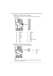
Motherboard Manual ATXPWR1: ATX Power Source Connector This connector allows user to connect 24-pin power connector on the ATX power supply. 12 24 1 13 Pin ...
Motherboard Manual ATXPWR1: ATX Power Source Connector This connector allows user to connect 24-pin power connector on the ATX power supply. 12 24 1 13 Pin ...

Setup Manual
Page 15
...-Express 1.0a compliant. - PCI1 PCI2 PCI3 13 PEX16_1 PEX1_1 PEX1_2 PCI1~PCI3: Peripheral Component Interconnect Slots This motherboard is a bus standard for Peripheral Component Interconnect, and it is equipped with 3 standard PCI slots. T41 HD PEX16_1: PCI-Express x16 Slot - PCI stands for expansion cards. This PCI slot is designated as 32 bits...
...-Express 1.0a compliant. - PCI1 PCI2 PCI3 13 PEX16_1 PEX1_1 PEX1_2 PCI1~PCI3: Peripheral Component Interconnect Slots This motherboard is a bus standard for Peripheral Component Interconnect, and it is equipped with 3 standard PCI slots. T41 HD PEX16_1: PCI-Express x16 Slot - PCI stands for expansion cards. This PCI slot is designated as 32 bits...
Setup Manual
Page 16
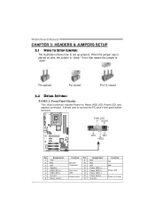
... Pin closed Pin1-2 closed 3.2 DETAIL SETTINGS PANEL1: Front Panel Header This 16-pin connector includes Power-on, Reset, HDD LED, Power LED, and speaker connection. Motherboard Manual CHAPTER 3: HEADERS & JUMPERS SETUP 3.1 HOW TO SETUP JUMPERS The illustration shows how to connect the PC case's front panel switch functions.
... Pin closed Pin1-2 closed 3.2 DETAIL SETTINGS PANEL1: Front Panel Header This 16-pin connector includes Power-on, Reset, HDD LED, Power LED, and speaker connection. Motherboard Manual CHAPTER 3: HEADERS & JUMPERS SETUP 3.1 HOW TO SETUP JUMPERS The illustration shows how to connect the PC case's front panel switch functions.

Setup Manual
Page 17
... connected with internal USB devices, like USB card reader. Reset your desired password or clear the CMOS data. 15 T41 HD F_USB1/F_USB2: Headers for five seconds. 4. Set the jumper to avoid damaging the motherboard. 3 1 Pin 1-2 Close: Normal Operation (default). 3 3 1 1 Pin 2-3 Close: Clear CMOS data. ※ Clear CMOS Procedures: 1. Please carefully follow the...
... connected with internal USB devices, like USB card reader. Reset your desired password or clear the CMOS data. 15 T41 HD F_USB1/F_USB2: Headers for five seconds. 4. Set the jumper to avoid damaging the motherboard. 3 1 Pin 1-2 Close: Normal Operation (default). 3 3 1 1 Pin 2-3 Close: Clear CMOS data. ※ Clear CMOS Procedures: 1. Please carefully follow the...
Setup Manual
Page 18
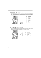
This header allows only HD audio front panel connector; Pin Assignment 4 1 Left Channel Input 2 Ground 3 Ground 1 4 Right Channel Input 16 AC'97 connector is not acceptable. 2 10 Pin Assignment 1 Mic ... 10 Jack Sense 1 9 CD_IN1: CD-ROM Audio-in Connector This connector allows user to connect the front audio output cable with the PC front panel. Motherboard Manual F_AUDIO1: Front Panel Audio Header This header allows user to connect the audio source from the variaty devices, like CD-ROM, DVD-ROM, PCI...
This header allows only HD audio front panel connector; Pin Assignment 4 1 Left Channel Input 2 Ground 3 Ground 1 4 Right Channel Input 16 AC'97 connector is not acceptable. 2 10 Pin Assignment 1 Mic ... 10 Jack Sense 1 9 CD_IN1: CD-ROM Audio-in Connector This connector allows user to connect the front audio output cable with the PC front panel. Motherboard Manual F_AUDIO1: Front Panel Audio Header This header allows user to connect the audio source from the variaty devices, like CD-ROM, DVD-ROM, PCI...
Setup Manual
Page 20
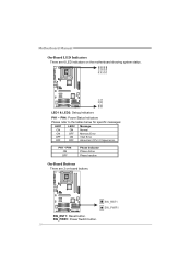
Motherboard Manual On-Board LED Indicators There are 2 on the motherboard showing system status. SW_PWR1: Power Switch button. 18 SW_RST1 SW_PWR1 SW_RST1: Reset button. PH1 ~ PH4 ON OFF Phase Indicator Phase Active Phase Inactive On-Board Buttons There are 6 LED indicators on -board buttons. PH 4 PH 3 PH 2 PH 1 LED2 LED1 LED1 & LED2: Debug Indicators PH1 ~ PH4: Power Status Indicators Please refer to the tables below for specific messages: LED1 LED2 Message ON ON OFF OFF ON Normal OFF Memory Error ON VGA Error OFF Abnormal: CPU / Chipset error.
Motherboard Manual On-Board LED Indicators There are 2 on the motherboard showing system status. SW_PWR1: Power Switch button. 18 SW_RST1 SW_PWR1 SW_RST1: Reset button. PH1 ~ PH4 ON OFF Phase Indicator Phase Active Phase Inactive On-Board Buttons There are 6 LED indicators on -board buttons. PH 4 PH 3 PH 2 PH 1 LED2 LED1 LED1 & LED2: Debug Indicators PH1 ~ PH4: Power Status Indicators Please refer to the tables below for specific messages: LED1 LED2 Message ON ON OFF OFF ON Normal OFF Memory Error ON VGA Error OFF Abnormal: CPU / Chipset error.
Setup Manual
Page 22
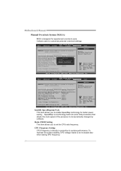
Motherboard Manual Manual Overclock System (M.O.S.) MOS is directly in proportion to system performance. To maintain the system stability, CPU voltage needs to be dynamically changed by ...
Motherboard Manual Manual Overclock System (M.O.S.) MOS is directly in proportion to system performance. To maintain the system stability, CPU voltage needs to be dynamically changed by ...
Setup Manual
Page 24
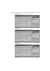
... Exit T-Series Settings Options WARNING: Please Clear CMOS if system no display after overclocking. V12 Tech Engine This engine will make a good over-clock performance. Motherboard Manual V6 Tech Engine This engine will make a best over -clock performance. Main Advanced BIOS SETUP UTILITY PCIPnP Boot Chipset T-Series Exit T-Series Settings Options...
... Exit T-Series Settings Options WARNING: Please Clear CMOS if system no display after overclocking. V12 Tech Engine This engine will make a good over-clock performance. Motherboard Manual V6 Tech Engine This engine will make a best over -clock performance. Main Advanced BIOS SETUP UTILITY PCIPnP Boot Chipset T-Series Exit T-Series Settings Options...
Setup Manual
Page 26
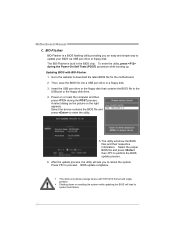
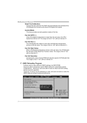
Insert the USB pen drive or the floppy disk that contains the BIOS file to download the latest BIOS file for the motherboard. 2. The BIO-Flasher is a BIOS flashing utility providing you to system boot failure. 24 Updating BIOS with FAT32/16 format and single partition. ...to the website to the USB port or the floppy disk drive. 4. Then, save the BIOS file into a USB pen drive or a floppy disk. 3. Motherboard Manual C. z This utility only allows storage device with BIO-Flasher 1. To enter the utility, press during the POST process. A select dialog as the picture on...
Insert the USB pen drive or the floppy disk that contains the BIOS file to download the latest BIOS file for the motherboard. 2. The BIO-Flasher is a BIOS flashing utility providing you to system boot failure. 24 Updating BIOS with FAT32/16 format and single partition. ...to the website to the USB port or the floppy disk drive. 4. Then, save the BIOS file into a USB pen drive or a floppy disk. 3. Motherboard Manual C. z This utility only allows storage device with BIO-Flasher 1. To enter the utility, press during the POST process. A select dialog as the picture on...
Setup Manual
Page 28
... fan will raise the speed of 1. Fan Ctrl OFF(℃) If the CPU/System temperature is from 0~127, with an interval of CPU/System fan. Motherboard Manual Smart Fan Calibration Choose this set value. Fan Ctrl Sensitive Increasing the value of the fan.
... fan will raise the speed of 1. Fan Ctrl OFF(℃) If the CPU/System temperature is from 0~127, with an interval of CPU/System fan. Motherboard Manual Smart Fan Calibration Choose this set value. Fan Ctrl Sensitive Increasing the value of the fan.
Setup Manual
Page 30
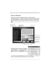
... e the name of the power supply manufacturer and the model no. This utility will see a saving dialog appears asking you to enter file name. 28 Motherboard Manual eHot-Line (Optional) eHot-Line is useful for your default e-mail clientapplication program. * represent s import ant information that helps you to contact with our...
... e the name of the power supply manufacturer and the model no. This utility will see a saving dialog appears asking you to enter file name. 28 Motherboard Manual eHot-Line (Optional) eHot-Line is useful for your default e-mail clientapplication program. * represent s import ant information that helps you to contact with our...

Setup Manual
Page 31
...provide your system information including motherboard/BIOS/CPU/video/ device/OS information. We will not share customer's data with other third parties, so please feel free to our tech support with any other e-mail application. This information is also concluded in the sent mail. T41 HD Open the saved .txt... file, you will be saved to the following web http://www.biostar.com.tw/app/en-us/about/contact.php for getting our contact information. 29 Your system...
...provide your system information including motherboard/BIOS/CPU/video/ device/OS information. We will not share customer's data with other third parties, so please feel free to our tech support with any other e-mail application. This information is also concluded in the sent mail. T41 HD Open the saved .txt... file, you will be saved to the following web http://www.biostar.com.tw/app/en-us/about/contact.php for getting our contact information. 29 Your system...

